Table of Contents
Advertisement
Quick Links
Download this manual
See also:
Reference Manual
Advertisement
Table of Contents

Related Manuals for Cabletron Systems MMAC-Plus 9E423-24


Summary of Contents for Cabletron Systems MMAC-Plus 9E423-24
- Page 1 ™ MMAC-Plus 9E423-24 Ethernet SmartSwitch Module User’s Guide...
- Page 2 Notice Notice Cabletron Systems reserves the right to make changes in specifications and other information contained in this document without prior notice. The reader should in all cases consult Cabletron Systems to determine whether any such changes have been made. The hardware, firmware, or software described in this manual is subject to change without notice.
-
Page 3: Fcc Notice
Notice FCC Notice This device complies with Part 15 of the FCC rules. Operation is subject to the following two conditions: (1) this device may not cause harmful interference, and (2) this device must accept any interference received, including interference that may cause undesired operation. NOTE: This equipment has been tested and found to comply with the limits for a Class A digital device, pursuant to Part 15 of the FCC rules. -
Page 4: Doc Notice
Notice DOC Notice This digital apparatus does not exceed the Class A limits for radio noise emissions from digital apparatus set out in the Radio Interference Regulations of the Canadian Department of Communications. Le présent appareil numérique n’émet pas de bruits radioélectriques dépassant les limites applicables aux appareils numériques de la class A prescrites dans le Règlement sur le brouillage radioélectrique édicté... -
Page 5: Table Of Contents
Chapter 2 Installing the 9E423-24 Module Unpacking the Module... 2-1 User Accessible Components ... 2-2 Setting the 9E423-24 Module DIP Switch ... 2-3 Installing the Module in the MMAC-Plus Chassis ... 2-5 The Reset Switch ... 2-7 Telco Connector ... 2-8... - Page 6 Contents Physical ... 5-2 Dimensions: ... 5-2 Weight: ... 5-2 Environment: ... 5-3...
-
Page 7: Chapter 1 Introduction
RISC-Based Architecture. The module can operate in two modes; as a 24 port Ethernet traditional switch (using 802.1d standards) with a high speed backbone connection or as a Secure Fast Switch (SFS) with 24 Ethernet connections. Each port of the 9E423-24 can be configured to operate in the Full Duplex mode. -
Page 8: Features
Spanning Tree, RMON, and MIB support within a scalable RISC-Based architecture. Fast Packet Switching The 9E423-24 incorporates a hardware based switch design referred to as the SmartSwitch ASIC, a collection of custom ASICs designed specifically for high speed switching. Because all frame translation, address lookups, and forwarding decisions are performed in hardware, the 9E423-24 can obtain a throughput performance of greater than 750K pps. - Page 9 Management Information Base (MIB) Support The 9E423-24 provides MIB support including: • RMON (RFC-1271) • IETF MIB II (RFC-1213) • IETF Bridge MIB (RFC-1493) and a host of other Cabletron Enterprise MIBs. For a complete list of supported MIBs, refer to the release notes provided in the 9E423-24 package.
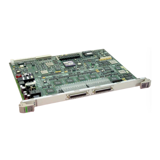
- Page 10 Introduction MAPLE 9E423-24 Figure 1-1. The 9E423-24 Module...
-
Page 11: Related Manuals
Related Manuals The manuals listed below should be used to supplement the procedures and technical data contained in this manual. MMAC-Plus Installation Guide MMAC-Plus 9C300-1 Environmental Module User’s Guide MMAC-Plus 9C214-1 AC Power Supply User’s Guide MMAC-Plus Local Management User’s Guide INB Terminator Modules Installation Guide Getting Help If you need additional support with the MMAC-Plus, or if you have any... - Page 12 Introduction...
-
Page 13: Installing The 9E423-24 Module
Installing the 9E423-24 Module The 9E423-24 module occupies a single slot in the MMAC-Plus chassis. The INB Terminator Modules must be installed on the rear of the chassis before powering NOTE up this module. Refer to the INB Terminator Modules Installation Guide for information and installation procedure. -
Page 14: User Accessible Components
User Accessible Components Figure 2-1 shows the various components that can be accessed by users. These consist of an eight position dip switch (explained in the next section), replaceable PROMs, and sockets for memory and flash upgrades. These will be used for future upgrades. -
Page 15: Setting The 9E423-24 Module Dip Switch
Setting the 9E423-24 Module DIP Switch The DIP switch on the 9E423-24 Module (Figure 2-1 and Figure 2-2), is an eight switch DIP located near the bottom left corner of the module. Each switch is set according to the functions described in Table 2-1. - Page 16 1. Caution: Do not toggle Switch 8 unless you intend to reset the user configured passwords to the factory default settings. CAUTION 2. Caution: Do not toggle Switch 7 unless you intend to reset the user entered parameters to the factory default settings. Table 2-1. Function of DIP Switch...
-
Page 17: Installing The Module In The Mmac-Plus Chassis
Installing the Module in the MMAC-Plus Chassis To install the 9E423-24 Module, in the MMAC-Plus Chassis, follow the steps below: Remove the blank panel, covering the slot in which the module will be mounted. All other slots must be covered to ensure proper airflow and cooling. - Page 18 Installing the 9E423-24 Module Metal Back-Panel Warning: Ensure that the circuit card is between the card guides. Lock down the top and bottom plastic tabs at the same time, applying even pressure. Figure 2-3. Installing the 9E423-24 Module FLNK FLNK FLNK FLNK FLNK...
-
Page 19: The Reset Switch
The Reset Switch The Reset switch is located on the front panel, under the top plastic tab as shown in Figure 2-4. It serves three functions: resetting the i960 processor, shutting down the module, or restarting the module. • To reset the i960 processor, press the reset switch twice within three seconds. -
Page 20: Telco Connector
Installing the 9E423-24 Module Telco Connector The 9E423-24 front panel has two RJ-71 Telco connectors each supporting 12 10BASE-T ports. Figure 2-5 illustrates an RJ-71 Telco Connector. Table 2-2 details the pinout connections for an RJ-71 Telco connector. Figure 2-5. RJ-71 Telco Connector Table 2-2. - Page 21 Table 2-2. Pinout Connections RJ-71 Telco Connector (Continued) Signal Wire Color TX 8- Blue Yellow RX 9- Orange/Yellow TX 9- Green/Yellow RX 10- Brown/Yellow TX 10- Gray/Yellow RX 11- Blue Violet TX 11- Orange/Violet RX 12- Green/Violet TX 12- Brown/Violet Gray/Violet Telco Connector Signal...
-
Page 22: Chapter 3 Operation
Network Interface Block (INB NIB) converts data packets received from the INB into a canonical format before forwarding to the SmartSwitch ASIC. Ethernet Ports ENIB Diagnostic ENIB i960 Controller Processor DC/DC Convertor ENIB Smart Switch ASIC ENIB ENIB ENIB Figure 3-1. Packet Flow Chapter 3 SMB 1 SMB 10... -
Page 23: Enib
SmartSwitch ASIC The SmartSwitch ASIC is a hardware based switch design that is the key building block of the MMAC-Plus hub. The SmartSwitch ASIC makes all filtering/ forwarding decisions in custom hardware as opposed to software like in traditional bridges. -
Page 24: I960 Core
i960 Core The i960 core provides the SNMP protocol stacks, to support industry standard MIBs. Additionally, Cabletron enterprise extension MIBs are supported for each media type. Advanced management services, such as the Distributed LAN Monitor, telnet and network address to MAC address mapping, are also provided by the i960 core. -
Page 25: System Diagnostic Controller
Operation The SMB-10 is externalized from the chassis via an optional Ethernet Port Interface Module (EPIM) located on the front of the Environmental Module. Through an EPIM connection, full SNMP management of the MMAC-Plus is available side-band from user data. Modules which share the SMB-10 bus periodically send out loop-back packets to ensure the validity of SMB-10. -
Page 26: Lanview Leds
LANVIEW LEDs The front panel LANVIEW LEDs indicate the status of the module and may be used as an aid in troubleshooting. Shown in Figure 4-1 are the LANVIEW LEDs of the 9E423-24 module. INB Receive ETHERNET System Status 9E423-24 INB Transmit Port Receive... - Page 27 LANVIEW LEDs The function of the two System Status LEDs, System Management Bus (SMB) and CPU (Central Processing Unit), are listed in Table 4-1. Table 4-1. System Status (SMB and CPU) LEDs LED Color State Green Functional Yellow Testing Yellow (Flashing) Crippled Yellow/Green Booting...
- Page 28 The function of the Port Receive LEDs are listed in Table 4-4. LED Color Green Link, no activity port enabled Green (Flashing) Link, port disabled Yellow (Flashing) Link, activity, port enabled (flashing to steady on indicates rate) Fault No link, (port disabled) The function of the Port Transmit LEDs are listed in Table 4-5.
-
Page 29: Chapter 5 Specifications
Specifications Technical Specifications CPU: Intel i960 RISC based microprocessor Memory: 4 Meg. Local RAM (expandable to 12 Meg.) 4 Meg. Flash Memory (expandable to 14 Meg.) 2 Meg. Packet RAM 16 Meg. DRAM (expandable to 16 Meg.) Standards: IEEE 802.1D IEEE 802.3i 10BASE-T Network Interfaces: RJ-71 Connectors... -
Page 30: Dimensions:
Specifications Safety It is the responsibility of the person who sells the system to which the module will be a part to ensure that the total system meets allowed limits of conducted and radiated emissions. CAUTION This equipment meets the safety requirements of: UL 1950 CSA C22.2 No. -
Page 31: Environment:
Environment: Operating Temperature Storage Temperature Relative Humidity 5 to 40 C -30 to 90 C 5% to 95% non-condensing Physical...
Need help?
Do you have a question about the MMAC-Plus 9E423-24 and is the answer not in the manual?
Questions and answers