
Related Manuals for DMP Electronics RoBoard RM-G145


Summary of Contents for DMP Electronics RoBoard RM-G145
- Page 1 RoBoard Module RM-G145 Manual V1.01 The Heart of Robotics Jun 2010 DMP Electronics Inc...
- Page 2 No part of this manual may be reproduced, copied, translated or transmitted, in whole or in part, in any form or by any means without the prior written permission of the DMP Electronics Inc. Copyright 2010 DMP Electronics Inc. Manual No. RM-G145-01 Ver.1.01...
-
Page 3: Table Of Contents
T a b l e O f C o n t e n t s C h a p t e r 1 .................... 4 Introduction ................ 4 1.1 Packing List............4 1.2 Product Description..........5 1.3 Specifications ............6 1.4 I C Address ............ -
Page 4: Chapter 1
C h a p t e r Introduction 1.1 Packing List Product Name Package RM-G144 RoBoard Module RM-G145 1x6 pin Cable x 1 Cable-RM-1 RoBoard Module RM-G145 The Heart of Robotics www.RoBoard.com... -
Page 5: Product Description
1.2 Product Description The RoBoard Module RM-G145 is fully integrated 3-axis (X-Y-Z) integrated dual-axis angular rate sensor (gyroscope), with the IDG-650 and ISZ-650 simply and all done through I2C interface, the dimension of it is wee as 20 x 20 mm. The IDG-650 gyro includes the integrated electronics necessary for application-ready functionality. -
Page 6: Specifications
1.3 Specifications RM-G145 Gyro Module Dual gyroscope IDG-650 X and Y axis Z axis gyroscope ISZ-650 Z axis AD7998 Interface 0x21 Default Address 1.25mm 6-pin wafer for I C x 2 Connectors DC-in 5V Power Input 20mm X 20mm Dimension 2.5g Weight RoBoard Module RM-G145... -
Page 7: I C Address
1.4 I C Address AD7998 I C address (7 bit address) : 0x21 RoBoard Module RM-G145 The Heart of Robotics www.RoBoard.com... -
Page 8: Board Dimension
1.5 Board Dimension RoBoard Module RM-G145 The Heart of Robotics www.RoBoard.com... -
Page 9: Installation
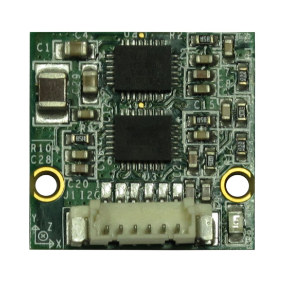
C C h a p t e r 2 Installation 2.1 Board Outline Top Side Bottom Side RoBoard Module RM-G145 The Heart of Robotics www.RoBoard.com... -
Page 10: Connectors & Pin 1 Location
2.2 Connectors & Pin 1 Location Connectors Top Side Bottom Side Pin 1 Location Top Side Bottom Side RoBoard Module RM-G145 The Heart of Robotics www.RoBoard.com... -
Page 11: Connectors & Jumpers Summary
2.3 Connectors & Jumpers Summary Summary Table Description Type of Connections C connector (Top) 6-pin Wafer, 2.54mm,6x1 C connector (Bottom) 6-pin Wafer, 2.54mm,6x1 RoBoard Module RM-G145 The Heart of Robotics www.RoBoard.com... -
Page 12: Pin Assignments
2.4 Pin Assignments J1: I C connector (Top) Pin # Signal Name Vcc (Red) GND (Black) SCL (Blue) SDA (Green) X (White) X (Orange ) J2: I C connector (Bottom) Pin # Signal Name Vcc (Red) GND (Black) SCL (Blue) SDA (Green) X (White) X (Orange ) -
Page 13: Development Note
C C h a p t e r Development Note Sample and development code The RM-G144 provides sample and development code. Please download from official website: http://www.roboard.com RoBoard Module RM-G145 The Heart of Robotics www.RoBoard.com... - Page 14 Warranty This product is warranted to be in good working order for a period of one year from the date of purchase. Should this product fail to be in good working order at any time during this period, we will, at our option, replace or repair it at no additional charge except as set forth in the following terms.
Need help?
Do you have a question about the RoBoard RM-G145 and is the answer not in the manual?
Questions and answers