Table of Contents
Advertisement
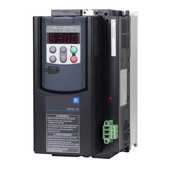
■Three-phase 400 V : FRN0010LM2C-4E to FRN0032LM2C-4E
Thank you for purchasing our FRENIC-Lift LM2C series of inverters.
• This product is designed to drive three-phase induction motors. Read through this manual to become
familiar with the handling procedure and correct use.
• Improper handling might result in incorrect operation, short life cycle, or failure of this product as well as the
motor.
• Deliver this manual to the end user of this product. Keep this manual in a safe place until this product is
discarded.
• For instructions on how to use an optional device, refer to the instruction and installation manuals for that
optional device.
Fuji Electric Co., Ltd.
LM2C series
Instruction Manual
INR-SI47-2224b-E
Advertisement
Table of Contents

Related Manuals for Fuji Electric FRENIC-Lift LM2C Series


Summary of Contents for Fuji Electric FRENIC-Lift LM2C Series
- Page 1 LM2C series ■Three-phase 400 V : FRN0010LM2C-4E to FRN0032LM2C-4E Thank you for purchasing our FRENIC-Lift LM2C series of inverters. • This product is designed to drive three-phase induction motors. Read through this manual to become familiar with the handling procedure and correct use.
- Page 2 Copyright © 2019 Fuji Electric Co., Ltd. All rights reserved. No part of this publication may be reproduced or copied without prior written permission from Fuji Electric Co., Ltd. All products and company names mentioned in this manual are trademarks or registered trademarks of their respective holders.
-
Page 3: Safety Precautions
This instruction manual is the original instructions and provides only minimum requisite information for wiring and operation of the product. Read through this manual before use. For details about this product, refer to the FRENIC-Lift LM2C series Reference Manual that contains the precautions, detailed functions, specifications and configuration. - Page 4 Installation • Install the inverter on a base made of metal or other non-flammable material. Otherwise, a fire could occur. • Do not place flammable object nearby. Doing so could cause fire. • Do not support the inverter by its front cover during transportation. Doing so could cause a drop of the inverter and injuries.
- Page 5 • Ensure that the number of input phases and the rated voltage of the product match the number of phases and the voltage of the AC power supply to which the product is to be connected. Otherwise, a fire or an accident could occur. •...
- Page 6 • If the user configures the function codes wrong without completely understanding this Instruction Manual and the FRENIC-Lift LM2C series Reference Manual, the motor may rotate with a torque or at a speed not permitted for the machine. An accident or injuries could occur.
- Page 7 Maintenance and inspection, and parts replacement • Before proceeding to maintenance or inspection, turn OFF the power and wait at least 10 minutes. Make sure that the charging lamp is turned OFF. Further, make sure, using a multimeter or a similar instrument, that the DC link bus voltage between the terminals P(+) and N(-) has dropped to the safe level (+25 VDC or below).
-
Page 8: Conformity To The Low Voltage Directive In The Eu
Conformity to the Low Voltage Directive in the EU If installed according to the guidelines given below, inverters marked with CE are considered as compliant with the Low Voltage Directive. Compliance with European Standards Adjustable speed electrical power drive systems (PDS). Part 5-1: Safety requirements. - Page 9 Conformity to the Low Voltage Directive in the EU (Continued) 5. The inverter should be used in an environment that does not exceed Pollution Degree 2 requirements. If inverters are to be used in an environment with pollution Degree 3 or 4, place them in an enclosure of IP54 or above.
- Page 10 Conformity to the Low Voltage Directive in the EU (Continued) 10. The inverter has been tested according to IEC/EN 61800-5-1 Short-circuit Test under the following conditions. Short-circuit current in the supply: 10,000 A 480V or below (400V class series inverters) 11.
-
Page 11: Conformity With Canadian Standards And U.s. Standards
Conformity with Canadian standards and U.S. standards The inverters with CSA “C/US” marking are subject to the regulations set forth by the Canadian and U.S. standards by installation within precautions listed below. 1. Solid state motor overload protection (motor protection by electronic thermal overload relay) is provided in each model. - Page 12 Conformity with Canadian standards and U.S. standards (Continued) 4. Use wires listed in CSA or UL. Copper wire size AWG (mm Main terminal *1 Main power input Inverter Inverter type outputs Inverter’s [U, V, W] grounding [ G] FRN0010LM2C-4 (2.1) FRN0015LM2C-4...
- Page 13 Conformity with Canadian standards and U.S. standards (Continued) 5. Install CSA or UL certified fuses or Circuit breaker between the power supply and the inverter, referring to the table below. Circuit breaker (MCCB) Fuse rating [A] (Class) RCD/ELCB etc Inverter type With Without With...
-
Page 14: Product Warranty
1) In the event that breakdown occurs during the product's warranty period which is the responsibility of Fuji Electric, Fuji Electric will replace or repair the part of the product that has broken down free of charge at the place where the product was purchased or where it was delivered. However, if the following cases are applicable, the terms of this warranty may not apply. - Page 15 Depending on the request, these can be discussed separately. [ 6 ] Applicable scope of service Above contents shall be assumed to apply to transactions and use in the country where you purchased the products. Consult your local supplier or Fuji Electric representative for details. xiii...
-
Page 16: Table Of Contents
Table of Contents Preface ................... i Safety precautions .............. i Conformity to the Low Voltage Directive in the EU ....vi Conformity with Canadian standards and U.S. standards ..ix Product warranty ..............xii Chapter 1 BEFORE USE ..........1-1 1.1 Acceptance Inspection and Appearance of Product .............. - Page 17 MEMO...
-
Page 18: Chapter 1 Before Use
Chapter 1 BEFORE USE 1.1 Acceptance Inspection and Appearance of Product Unpack the package and check the following: (1) An inverter and the following accessories are contained in the package. Instruction manual (this book) Main circuit wiring connector (2) The inverter has not been damaged during transportation—there should be no dents or parts missing. (3) The inverter is the type you ordered. -
Page 19: Precautions For Using Inverters
(1) The maximum wiring distance between an inverter and a motor The maximum wiring is 20m. When using wire longer than the specification, that may not be able to control a motor. If longer secondary wiring is required, consult your Fuji Electric representative. Power input... -
Page 20: Usage Environment And Storage Environment
1.3 Usage environment and Storage environment This section provides precautions when handling inverters, e.g. precautions for installation environment and storage environment. 1.3.1 Usage environment Install the inverter in an environment that satisfies the requirements listed in Table below. Site location Indoors Ambient temperature -10 to +45°C... -
Page 21: Storage Environment
1.3.2 Storage environment The storage environment in which the inverter should be stored after purchase differs from the usage environment. Store the inverter in an environment that satisfies the requirements listed below. [1] Temporary storage Table1.1 Storage and Transport Environments Item Specifications Storage temperature *1... -
Page 22: Chapter 2 Mounting And Wiring The Inverter
Chapter 2 MOUNTING AND WIRING THE INVERTER 2.1 Installing the Inverter (1) Mounting base Install the inverter on a base made of metal or other non-flammable material. Do not mount the inverter upside down or horizontally. (2) Clearances Ensure that the minimum clearances indicated in Figure 2.1 and Table 2.1 are maintained at all times. -
Page 23: Wiring
2.2 Wiring Follow the procedure below. In the following description, it is assumed that the inverter has already been installed. 2.2.1 Removing the front cover ① Remove the keypad blind cover and loosen the screws ② Hold the right and left ends of the front cover and remove it. Blind cover Screw Front cover... -
Page 24: Terminal Arrangement Diagrams And Screw Specifications
2.2.3 Wire sizes For the wire sizes for the main circuits, refer to the "Conformity to the Low Voltage Directive in the EU" given in Preface. Terminals for the main circuits should have insulation, insulation tubes, or similar treatment. 2.2.4 Terminal arrangement diagrams and screw specifications The tables and figures given below show the screw specifications and terminal arrangement diagrams. - Page 25 ◆ FRN0010LM2C-4□to FRN0025LM2C-4□ Short circuit terminals Grounding terminals (For manufacturer) 24VDC input terminals Input terminals Output terminals Main circuit terminals Output Main circuit Short circuit 24VDC input Grounding Input terminals terminals Terminals terminals terminals terminals (For manufacturer) ◆ FRN0032LM2C-4□ Short circuit terminals Grounding terminals (For manufacturer) 24VDC input terminals...
- Page 26 Connection method with shield plate of input and output terminals. Tightwire (FRN0010LM2C-4□to FRN0032LM2C-4□)
- Page 27 (2) Arrangement of control circuit terminals Table 2.3 Control Circuit Terminals Screw specifications Wire strip length Recommended Type of screwdriver Terminal block type wire size (mm (tip shape) Screw Tightening size torque 0.20 to 3.31 mm Flat screwdriver Relay terminals M2.5 0.39±10% N·m (AWG24 to 12)
-
Page 28: Terminal Functions And Wiring Order
DC link bus terminals P(+), N(-) When you need to use the DC link bus terminals P(+) and N(-), consult your Fuji Electric representative. The three-phase input power lines or single-phase input power lines are connected to these terminals. Main circuit power input... - Page 29 Control circuit terminals Table 2.5 Names, Symbols and Functions of the Control Circuit Terminals Classifi- Name Symbol Functions cation Analog setting voltage input [12] External voltage input that commands the frequency externally. (1) Input voltage range : 0 to ±10VDC / 0 to ±100% (2) Hardware specifications ・Input impedance : 22 kΩ...
- Page 30 Table 2.5 Names, Symbols and Functions of the Control Circuit Terminals (continued) Classifi- Name Symbol Functions cation Enable input 1 [EN1] (1) Opening the circuit between terminals [EN1] and [PLC] or Enable input 2 [EN2] terminals [EN2] and [PLC] stops the operation of the inverter output transistorby STO functional safety function according to IEC/EN 61800-5-2.
- Page 31 Table 2.5 Names, Symbols and Functions of the Control Circuit Terminals (continued) Classifi- Name Functions Symbol cation These terminals output monitor signals for analog DC voltage (-10 Analog monitor [FMA] Analog to +10 V). output Analog common Common terminal for analog output signals. [11] Both the SINK and SOURCE modes are supported.
- Page 32 Table 2.5 Names, Symbols and Functions of the Control Circuit Terminals (continued) Classifi- Name Symbol Functions cation General-purpose relay [Y3A/C] (1) Any one of output signals that can be assigned to terminals [Y1] outputs [Y4A/C] and [Y2] can also be assigned to this relay contacts, as a [Y5A/C] general-purpose relay output, in order to use it for outputting a signal.
-
Page 33: Connection Diagrams
2.2.6 Connection diagrams This section shows connection diagrams with the Enable input function used. FRN0010LM2C-4□to FRN0032LM2C-4□ DC REACTOR EXTERNAL BRAKING DCR (*3) RESISTOR (PLC) or (CM) (*7) (THR) RCD: Residual-current-operated protective device ELCB: Earth Leakage Circuit Breaker MCCB: Molded Case Circuit Breaker P(+) N(-) Fuse... - Page 34 (*1) Install a recommended molded case circuit breaker (MCCB) or residual-current-operated protective device (RCD)/earth leakage circuit breaker (ELCB) (with over current protection function) in the primary circuit of the inverter to protect wiring. (*2) Refer to table 2.4. (*3) Mount a jumper cable between terminals P2 and P3 when a DCR is not used. The direct current reactor (DCR) is a separately installed option.
-
Page 35: Setting The Slide Switches On The Control Pcb
Setting the slide switches on the control PCB Switching the slide switches located on the control PCB (see Figure 2.4) allows you to customize the operation mode of the analog output terminals, digital I/O terminals, and communications ports. To access the slide switches, remove the front cover so that you can see the control PCB. ... -
Page 36: Chapter 3 Operation Using The Keypad
I/O signal states, maintenance information, and alarm information. Keypad is available to the following ROM versions. Table 3.1 Keypad and ROM versions Keypad ROM versions TP-A1-LM2 8700 or later TP-E1U 1600 or later For details of the multi-function keypad, refer to the FRENIC-Lift LM2C series Reference Manual. -
Page 37: Chapter 4 Running The Motor For A Test
Chapter 4 RUNNING THE MOTOR FOR A TEST 4.1 Checking Prior to Powering ON Check the following before powering on the inverter. (1) Check that the wiring is correct. Especially check the wiring to the inverter input terminals L1/R, L2/S and L3/T and output terminals U, V, and W. -
Page 38: Configuring The Function Code Data Before Test Run
- The motor to be driven is not a Fuji product or is a non-standard product. - The cabling between the motor and the inverter is long. - A reactor is inserted between the motor and inverter. For details of motor tuning procedure refer to the FRENIC-Lift LM2C series Reference Manual. -
Page 39: Running The Inverter For Motor Operation Check
4.4 Running the Inverter for Motor Operation Check After preparations of 4.1-4.3 have been completed, begin to perform the test drive of the motor. Turn on both terminals [EN1] and [EN2] before running the motor. If terminals [EN1] or [EN2] and [PLC] are not connected, the motor doesn’t rotate. ------------------------------- Test Run Procedure using the multi-function keypad (option) ------------------------------ (1) Turn the power ON and check that the LCD monitor blink while indicating a reference speed of 0.00. -
Page 40: Chapter 5 Troubleshooting
Chapter 5 TROUBLESHOOTING 5.1 Alarm Codes Table 5.1 Quick List of Alarm Codes Code Name Description The inverter momentary output current exceeded the overcurrent level. Instantaneous overcurrent OC1: Overcurrent during acceleration OC2: Overcurrent during deceleration OC3: Overcurrent during running at a constant speed Zero-phase current caused by ground fault in the output Ground fault circuit has exceeded the allowable limit. - Page 41 An abnormality was diagnosed in EN1, EN2 terminals EN1, EN2 terminals circuit error circuit. * These alarms can change enable/disable by a function code. For detail of function code refer to the FRENIC-Lift LM2C series Reference Manual.
-
Page 42: Chapter 6 Maintenance And Inspection
Chapter 6 MAINTENANCE AND INSPECTION Perform daily and periodic inspections to avoid trouble and keep reliable operation of the inverter for a long time. 6.1 Daily Inspection Visually inspect the inverter for operation errors from the outside without removing the covers when the inverter is ON or operating. -
Page 43: List Of Periodic Replacement Parts
These parts are likely to deteriorate with age due to their construction and properties, leading to the decreased performance or failure of the inverter. When the replacement is necessary, consult your Fuji Electric representative. Table 6.2 Replacement Parts Standard replacement intervals (See Notes below.) -
Page 44: Inquiries About Product And Guarantee
Inverter type (Refer to Chapter 1, Section 1.1.) SER No. (serial number of the product) (Refer to Chapter 1, Section 1.1.) Function codes and their data that you changed (Refer to the FRENIC-Lift LM2C series Reference Manual) ROM version (Refer to FRENIC-Lift LM2C series Reference Manual) -
Page 45: Chapter 7 Specifications
Chapter 7 SPECIFICATIONS 7.1 Standard Model 1) Three-phase 400V series Item Specifications Type FRN___LM2C-4□ Nominal applied motor [kW] Rated capacity [kVA] Three-phase 380V-480V, 50/60Hz Rated voltage 21.4 (24.5) 18.5 Rated current Overload capacity [A] 33.3 44.1 57.6 (Permissible overload time) (3s) (3s) (3s) - Page 46 *7) Braking time and duty cycle (%ED) are defined by cycle operation at the rated regenerative power as shown in the figure below. Regenerative power [kW] Reated regenerative power Time [s] Braking time : T Braking time : T %ED = ×100 Cyclic period :T *8) Measured at 1m from inverter.
-
Page 47: External Dimensions
7.2 External Dimensions Power supply voltage Inverter type FRN0010LM2C-4□ FRN0015LM2C-4□ Three-phase 400V FRN0019LM2C-4□ FRN0025LM2C-4□... - Page 48 Power supply voltage Inverter type Three-phase 400V FRN0032LM2C-4□...
-
Page 49: Chapter 8 Conformity With Standards
<Precaution when exporting to Europe> ●Not all Fuji Electric products in Europe are necessarily imported by the above importer. If any Fuji Electric products are exported to Europe via another importer, please ensure that the importer is clearly stated by the customer. -
Page 50: Compliance With European Standards
Compliance with European Standards The CE marking on Fuji products indicates that they comply with the essential requirements of the Electromagnetic Compatibility (EMC) Directive, Low Voltage Directive, Machinery Directive and Lift Directive which are issued by the Council of the European Communities. The products comply with the following standards Table 8.1 Product Standards Compliance FRN0010LM2C-4□... -
Page 51: Compliance With Emc Standards
EMC Directive. Therefore, CE marking for the equipment shall be the responsibility of the equipment manufacturer. For this reason, Fuji Electric’s CE mark is indicated under the condition that the product shall be used within equipment meeting all requirements for the relevant Directives. Instrumentation of such equipment shall be the responsibility of the equipment manufacturer. -
Page 52: Harmonic Component Regulation In The Eu
4) If radiated noise emissions exceed the requirement by the standard, place a ferrite core on the input side of the inverter, as shown in Figure 8.2 Ferrite Core FRENIC-Lift L1/R From L2/S Power L3/T Supply Figure 8.2 Installation for ferrite core Harmonic Component Regulation in the EU 8.5.1 General comments When general-purpose industrial inverters are used in the EU, the harmonics emitted from inverters to the... -
Page 53: Compliance With Functional Safety Standard
8.6 Compliance with Functional Safety Standard 8.6.1 General In FRENIC-Lift series of inverters, opening the hardware circuit between terminals [EN1]-[PLC] or between terminals [EN2]-[PLC] stops the output transistor, coasting the motor to a stop (EN: Enable input). This is the Safe Torque Off (STO) compliant with Functional Safety Standard EN/IEC 61800-5-2. - Page 54 Enable terminals and peripheral circuit, and internal circuit configuration Conventional Inverter Safety circuit breakers complying with more than EN ISO 13849-1 Cat.3 Power supply External safety switch complying with more than EN ISO 13849-1 Cat.3, PL-e “Enable” input EN62061/EN61508 SIL3 Reset Emergency Stop Figure 8.4 Conventional Inverters compliant with...
-
Page 55: Notes For Compliance To Functional Safety Standard
Table 8.4 Operation of STO Functional Safety Function Digital input signals Alarm ECF Digital output signal Inverter status [EN1] [EN2] [Y*] (DECF) Shorted Shorted No issue Ready to run Issue Output shutdown (STO) Opened Opened No issue Output shutdown (STO) Issue Output shutdown (STO) Shorted... - Page 56 under Pollution Degree 3 environment the safety circuit that implements the STO functional safety function will not reduce its performance. Therefore, the STO function operation can be ensured even under Pollution Degree 3. - To bring the inverter into compliance with Functional Safety Standard, it is necessary to bring it into compliance with European Standards EN61800-5-1 and EN61800-3.
-
Page 57: Inverter Output State When Safe Torque Off (Sto) Is Activated
8.6.3 Inverter output state when Safe Torque Off (STO) is activated Turning the emergency stop button ON turns EN1 and EN2 OFF, bringing the inverter into the Safe Torque Off (STO) state. Figure 8.6 shows the timing scheme to apply when the emergency stop button is turned OFF with the inverter being stopped. - Page 58 Figure 8.7 shows the timing scheme to apply when the emergency stop button is turned ON with the inverter running. Input signals to EN1 and EN2 go OFF, bringing the inverter into the Safe Torque Off (STO) state and coasting the motor to a stop. Stop Run command Emergency stop...
-
Page 59: Ecf Alarm (Caused By Logic Discrepancy) And Inverter Output State
8.6.4 ECF alarm (caused by logic discrepancy) and inverter output state Figure 8.8 shows the timing scheme to apply when EN1 and EN2 inputs are not concordant, so that an alarm ECF occurs. Turning the emergency stop button ON turns EN1 and EN2 inputs OFF, which usually brings the inverter into the Safe Torque Off (STO) state. -
Page 60: Compliance With Canadian And U.s. Standards (Csa Certification)
8.7 Compliance with Canadian and U.S. Standards (CSA certification) 8.7.1 General The inverters with CSA “C/US” marking are certified for both U.S. and Canadian markets, to the applicable U.S. and Canadian standards. The products comply with the following standards Table 8.5 Product Standards Compliance FRN0010LM2C-4□... - Page 61 In no event will Fuji Electric Co., Ltd. be liable for any direct or indirect damages resulting from the application of the information in this manual.
- Page 62 Fuji Electric Co., Ltd. Gate City Ohsaki, East Tower, 11-2, Osaki 1-chome, Shinagawa-ku, Tokyo 141-0032, Japan Phone: +81 3 5435 7058 Fax: +81 3 5435 7420 http://www.fujielectric.com/...
Need help?
Do you have a question about the FRENIC-Lift LM2C Series and is the answer not in the manual?
Questions and answers