Fuji Electric Frenic Mini Series User Manual
Compact
Hide thumbs
Also See for Frenic Mini Series:
- User manual (269 pages) ,
- Brochure (33 pages) ,
- Instruction manual (192 pages)
Table of Contents
Advertisement
Quick Links
Advertisement
Chapters
Table of Contents

Related Manuals for Fuji Electric Frenic Mini Series


Summary of Contents for Fuji Electric Frenic Mini Series
- Page 1 MEHT530...
- Page 2 Compact Inverter User's Manual...
- Page 3 Copyright © 2002-2007 Fuji Electric FA Components & Systems Co., Ltd. All rights reserved. No part of this publication may be reproduced or copied without prior written permission from Fuji Electric FA Components & Systems Co., Ltd. All products and company names mentioned in this manual are trademarks or registered trademarks of their respective holders.
- Page 4 • FRENIC Loader Instruction Manual • Remote Keypad Instruction Manual • Built-in Braking Resistor Installation Manual The materials are subject to change without notice. Be sure to obtain the latest editions for use. Documents related to Fuji inverters Catalogs FRENIC5000G11S/P11S FRENIC-Eco...
-
Page 5: Safety Precautions
These safety precautions are of utmost importance and must be observed at all times. This product is not designed for use in appliances and machinery on which lives depend. Consult your Fuji Electric representative before considering the FRENIC-Mini series of inverters for equipment and machinery related to nuclear power control, aerospace uses, medical uses or transportation. -
Page 6: Precautions For Use
In the low-speed range, the cooling effect will be weakened, and temperature so decrease the output torque of the motor. If constant torque is required in rise the low-speed range, use a Fuji inverter motor or a motor equipped with an externally powered ventilating fan. In running general-... - Page 7 Avoid such operation. Synchronous It is necessary to take special measures suitable for this motor type. Contact In running motors your Fuji Electric representative for details. special motors Single-phase motors are not suitable for inverter-driven variable speed operation. Use three-phase motors.
- Page 8 Discontinuance of Do not mount power-factor correcting capacitors in the inverter’s primary power-factor circuit. (Use the DC reactor to improve the inverter power factor.) Do not correcting use power-factor correcting capacitors in the inverter output circuit. An capacitor overcurrent trip will occur, disabling motor operation. Discontinuance of Do not connect a surge killer to the inverter's secondary circuit.
- Page 9 How this manual is organized This manual contains chapters 1 through 9, appendices and glossary. Part 1 General Information Chapter 1 INTRODUCTION TO FRENIC-Mini This chapter describes the features and control system of the FRENIC-Mini series, and the recommended configuration for the inverter and peripheral equipment. Chapter 2 PARTS NAMES AND FUNCTIONS This chapter contains external views of the FRENIC-Mini series and an overview of terminal blocks, including a description of the LED display and keys on the keypad.
- Page 10 Part 5 Specifications Chapter 8 SPECIFICATIONS This chapter describes specifications of the output ratings, control system, and terminal functions for the FRENIC-Mini series of inverters. It also provides descriptions of the operating and storage environment, external dimensions, examples of basic connection diagrams, and details of the protective functions. Chapter 9 FUNCTION CODES This chapter contains overview lists of seven groups of function codes available for the FRENIC-Mini series of inverters and details of each function code.
-
Page 11: Table Of Contents
CONTENTS Part 1 General Information Chapter 1 INTRODUCTION TO FRENIC-Mini Features..............................1-1 Control System ............................1-8 Recommended Configuration ........................1-9 Chapter 2 PARTS NAMES AND FUNCTIONS External View and Allocation of Terminal Blocks..................2-1 LED Monitor, Potentiometer and Keys on the Keypad ................2-2 Chapter 3 OPERATION USING THE KEYPAD Overview of Operation Modes ......................... - Page 12 Chapter 5 RUNNING THROUGH RS-485 COMMUNICATION (OPTION) Overview on RS-485 Communication...................... 5-1 5.1.1 Common specifications........................5-2 5.1.2 Connector specifications ........................5-3 5.1.3 Connection ............................5-3 Part 3 Peripheral Equipment and Options Chapter 6 SELECTING PERIPHERAL EQUIPMENT Configuring the FRENIC-Mini......................... 6-1 Selecting Wires and Crimp Terminals.......................
- Page 13 Part 5 Specifications Chapter 8 SPECIFICATIONS Standard Models ............................8-1 8.1.1 Three-phase 230 V ..........................8-1 8.1.2 Three-phase 460 V ..........................8-2 8.1.3 Single-phase 230 V ..........................8-3 Models Available on Order ........................8-4 8.2.1 EMC filter built-in type........................8-4 8.2.1.1 Three-phase 230 V ........................
- Page 14 Appendices App.A Advantageous Use of Inverters (Notes on electrical noise)..............A-1 Effect of inverters on other devices....................A-1 Noise ..............................A-2 Noise prevention ..........................A-4 App.B Japanese Guideline for Suppressing Harmonics by Customers Receiving High Voltage or Special High Voltage ........................... A-12 Application to general-purpose inverters ..................
-
Page 16: Part 1 General Information
Part 1 General Information Chapter 1 INTRODUCTION TO FRENIC-Mini Chapter 2 PARTS NAMES AND FUNCTIONS Chapter 3 OPERATION USING THE KEYPAD... - Page 18 Chapter 1 INTRODUCTION TO FRENIC-Mini This chapter describes the features and control system of the FRENIC-Mini series, and the recommended configuration for the inverter and peripheral equipment. Contents 1.1 Features............................... 1-1 1.2 Control System............................1-8 1.3 Recommended Configuration ........................1-9...
-
Page 20: Features
Optimum performance for traversing conveyors • High starting torque, at 150% or more Equipped with Fuji's original simplified torque-vector control system and the automatic torque boost function, these inverters ensure consistent and powerful operation (when automatic torque boost and slip compensation control are ON and start frequency is set at 5 Hz or more). - Page 21 • Reduced motor instability at low speed Fuji's unique control method improves voltage control performance and reduces motor instability at low speed to about a half or under (at 1 Hz) compared with that of conventional inverters. Refer to Chapter 4, Section 4.7 "Drive Command Controller" for details.
- Page 22 More than one FRENIC-Mini inverter can be mounted side-by-side without any gap inside your system control panel, thereby reducing the amount of space required for installation. (Ambient temperature: 40°C (104°F) or lower) (Example: Inverters of 3-phase 230 V, 1 HP or less) • External dimensions compatible with Fuji FVR-C11S series...
- Page 23 • RS-485 communications card (option) can be installed internally This card can be installed inside the inverter's body without changing the dimensions. RS-485 communication is available as option. Refer to Chapter 5, "RUNNING THROUGH RS-485 COMMUNICATION (OPTION)." RS-485 communications card (option) (Example: Inverters of 3-phase 230 V, 1 HP or less) •...
- Page 24 1.1 Features • Easy-to-remove/replace terminal block covers (for control circuit and main circuit) • LED monitor on the keypad displaying all types of data You can access and monitor all types of inverter's data and information including output frequency, set frequency, load shaft speed, output current, output voltage, alarm history, input power etc.
- Page 25 Maintenance FRENIC-Mini series features the following facilities useful for maintenance. Refer to Chapter 3, Section 3.3.5 "Reading Maintenance Information" and the FRENIC-Mini Instruction Manual, Chapter 7 "MAINTENANCE AND INSPECTION" for details. • The lifetime of the DC link bus capacitor (reservoir capacitor) can be estimated The capacitor's condition compared with its initial state can be confirmed.
- Page 26 1.1 Features Flexible through optionals • Function code copy function The optional remote keypad includes a built-in copy facility, so you can copy function code data set in a source inverter and duplicate it into a destination inverter. • Inverter support loader software available The inverter support loader program (Windows-based), which simplifies the setting of function codes, is provided as an option.
-
Page 27: Control System
This "Simplified Torque-Vector Control" is unique to Fuji inverters. The control logic section, which is the very brain of the inverter, allows you to customize the inverter's driving patterns using the function code settings. -
Page 28: Recommended Configuration
1.3 Recommended Configuration 1.3 Recommended Configuration To control a motor with an inverter correctly, you should consider the rated capacity of both the motor and the inverter and ensure that the combination matches the specifications of the machine or system to be used. - Page 30 Chapter 2 PARTS NAMES AND FUNCTIONS This chapter contains external views of the FRENIC-Mini series and an overview of terminal blocks, including a description of the 7-segment LED monitor and keys on the keypad. Contents 2.1 External View and Allocation of Terminal Blocks..................2-1 2.2 LED Monitor, Potentiometer and Keys on the Keypad................
-
Page 32: External View And Allocation Of Terminal Blocks
2.1 External View and Allocation of Terminal Blocks 2.1 External View and Allocation of Terminal Blocks Figures 2.1 and 2.2 show the external and bottom views of the FRENIC-Mini. (1) External and bottom views Control circuit terminal block cover Keypad Nameplate Main circuit terminal Control circuit terminal... -
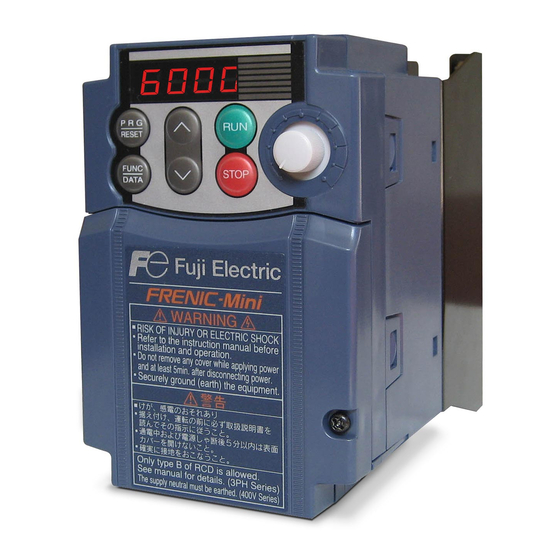
Page 33: Led Monitor, Potentiometer And Keys On The Keypad
2.2 LED Monitor, Potentiometer and Keys on the Keypad 7-segment As shown at the right, the keypad LED monitor Program/Reset key RUN key Potentiometer consists of a 7-segment LED monitor, a potentiometer (POT), and six keys. The keypad allows you to run and stop the motor, monitor running status, and switch to the menu mode. - Page 34 2.2 LED Monitor, Potentiometer and Keys on the Keypad ■ LED monitor In Running mode, the LED monitor displays running status information (output frequency, current or voltage); in Programming mode, it displays menus, function codes and their data; in Alarm mode, it displays an alarm code which identifies the error factor if the protective function is activated.
- Page 35 ■ Continuous holding-down function for Program/Reset Holding down the key longer (approx. one second or longer) moves the cursor on the LED monitor. In Running mode, the cursor moves along digits; in Programming mode, it moves not only along digits but to the next function code.
-
Page 36: Operation Using The Keypad
Chapter 3 OPERATION USING THE KEYPAD This chapter describes inverter operation using the keypad. The inverter features three operation modes (Running, Programming and Alarm modes) which enable you to run and stop the motor, monitor running status, set function code data, display running information required for maintenance, and display alarm data. Contents 3.1 Overview of Operation Modes........................ -
Page 38: Overview Of Operation Modes
3.1 Overview of Operation Modes 3.1 Overview of Operation Modes FRENIC-Mini features the following three operation modes: ■ Running mode : This mode allows you to enter run/stop commands in regular operation. You may also monitor the running status in realtime. ■... - Page 39 The figure below shows the transition between the running status monitoring screens in Running mode, that between the menu screens in Programming mode, and that between the alarm code screens in Alarm mode. *1 The speed monitor may display the output frequency (Hz), set frequency (Hz), load shaft speed (r/min), line speed [ft/min.
-
Page 40: Running Mode
3.2 Running Mode 3.2 Running Mode If the inverter is turned ON, it automatically enters Running mode in which you may: Run/stop the motor Set up the set frequency and others Monitor the running status (e.g., output frequency, output current) (4) Jog (inch) the motor 3.2.1 Run/stop the motor By factory default, pressing the... - Page 41 E48 data "LED monitor details Set frequency display Conversion of displayed value (Select speed monitor)" 0: Output frequency (before slip Frequency setting compensation) 1: Output frequency (after slip Frequency setting compensation) 2: Set frequency Frequency setting 4: Load shaft speed Load shaft speed setting Frequency setting x E50 5: Line speed...
-
Page 42: Monitor The Running Status
3.2 Running Mode Setting up the set frequency with keys under the PID control To set the set frequency with keys under the PID control, you need to specify the following conditions: - Set function code F01 to "0: Keypad operation." - Select frequency setting-1 (Frequency settings from communications link: Disabled, and Multistep frequency settings: Disabled) as manual speed command. - Page 43 Figure 3.3 shows the procedure example for selecting the desired monitor item. *1 The speed monitor may display the output frequency (Hz), set frequency (Hz), load shaft speed (r/min), line speed [ft/min. (m/min.)], and contrast feeding rate time (min.) which can be selected by setting up function code E48. *2 These PID-related information will appear only when the inverter is under the PID control.
-
Page 44: Jog (Inch) The Motor
3.2 Running Mode 3.2.4 Jog (inch) the motor In Running mode, pressing keys at the same time (simultaneous keying) can make the inverter ready for jogging. The JoG appears on the LED monitor. To return the inverter from the ready-to-jog state to the usual running state, you need to press keys simultaneously. -
Page 45: Programming Mode
3.3 Programming Mode Pressing the key in Running mode switches the inverter to Programming mode. This mode provides the following functions which can be easily selected with the menu-driven system. Data setting (Menu #1) Data checking (Menu #2) Drive monitoring (Menu #3) I/O checking (Menu #4) -
Page 46: Programming Mode
3.3 Programming Mode Limiting menus to be displayed The menu-driven system has a limiter function (specified by function code E52) that limits menus to be displayed for the purpose of simple operation. The factory default is to display Menu #1 "Data setting" only, allowing no switching to any other menu. - Page 47 Function codes that require simultaneous keying To change data for function codes F00 (Data Protection) and H03 (Data Initialization), simultaneous keying operation is necessary-- keys or keys. This prevents data from being lost by mistake. Changing, validating, and saving of function code data during running Some function code data can be changed while the motor is running and some cannot.
- Page 48 3.3 Programming Mode Figure 3.4 shows the status transition for Menu #1 "Data setting" and Figure 3.5 shows an example of the function code data changing procedure. Figure 3.4 Status Transition Diagram for "Data Setting" 3-11...
- Page 49 Figure 3.5 Example of Function Code Data Changing Procedure Basic key operation This section will give a description of the basic key operation, following the example of the function code data changing procedure shown in Figure 3.5. This example shows you how to change function code F01 data from the factory default of "Potentiometer operation on the keypad (F01 = 4)"...
-
Page 50: Checking Changed Function Codes--"Data Checking
3.3 Programming Mode 3.3.2 Checking changed function codes--"Data Checking" Menu #2 "Data checking" in Programming mode allows you to check function code data that have been changed. Only data that has been changed from the factory defaults are displayed on the LED monitor. You may refer to the function code data and change again if necessary. -
Page 51: Monitoring The Running Status--"Drive Monitoring
3.3.3 Monitoring the running status--"Drive Monitoring" Menu #3 "Drive monitoring" is used to check the running status during maintenance and test running. The display items for "Drive monitoring" are listed in Table 3.5. Using keys, you may check those items in succession. - Page 52 3.3 Programming Mode Figure 3.7 Drive Monitoring Status Transition Basic key operation keys to select "Drive monitoring" ( . (1) With the menu displayed, use (2) Press the key to display the desired code in the monitoring items list (e.g. (3) Use keys to select the desired monitoring item, then press the key.
- Page 53 Displaying running status To display the running status in hexadecimal format, each state has been assigned to bit 0 to 15 as listed in Table 3.6. Table 3.7 shows the relationship between each of the status assignments and the LED monitor display.
-
Page 54: Checking I/O Signal Status--"I/O Checking
3.3 Programming Mode Hexadecimal expression A 16-bit binary number is expressed in hexadecimal format (4 bits). Table 3.8 shows the expression corresponding to decimals. The hexadecimals are shown as they appear on the LED monitor. Table 3.8 Binary and Hexadecimal Conversion Binary Hexadecimal Decimal Binary... - Page 55 Figure 3.8 Status Transition of I/O Check Basic key operation keys to select "I/O check"( . (1) With the menu displayed, use (2) Press the key to display the codes for the I/O check item list. (e.g. (3) Use keys to select the desired I/O check item, then press the key.
- Page 56 3.3 Programming Mode [ 1 ] Displaying control I/O signal terminals The I/O signal status of control circuit terminals may be displayed with ON/OFF of the LED segment or in hexadecimal display. ■ Display I/O signal status with ON/OFF of the LED segment As shown in Table 3.10 and the figure below, segments "a"...
- Page 57 ■ Displaying I/O signal status in hexadecimal format Each I/O terminal is assigned to bit 15 through bit 0 as listed in Table 3.11. An unassigned bit is interpreted as "0." Allocated bit data is displayed on the LED monitor in 4-digit hexadecimals ("0" to "F" each).
-
Page 58: Reading Maintenance Information--"Maintenance Information
3.3 Programming Mode 3.3.5 Reading maintenance information--"Maintenance Information" Menu #5 "Maintenance information" in Programming mode contains information necessary for performing maintenance on the inverter. Table 3.12 lists the maintenance information display items and Figure 3.9 shows the status transition for maintenance information. Table 3.12 Maintenance Display Items LED monitor Display contents... -
Page 59: Reading Alarm Information--"Alarm Information
* The part in the dotted-line box is applicable only when a remote keypad is set up for operation. Figure 3.9 Status Transition of Maintenance Information Basic key operations keys to select "Maintenance information" ( . (1) With the menu displayed, use (2) Press the key to display the list of maintenance item codes (e.g. - Page 60 3.3 Programming Mode Table 3.13 Alarm Information Contents LED monitor Display contents Description shows: (Item No.) Output frequency Output frequency before slip compensation Present o Output current utput current Present o Output voltage utput voltage Set frequency Present set frequency Rotational direction This shows the rotational direction of a run command being output.
- Page 61 Table 3.13 Continued LED monitor Display contents Description shows: (Item No.) Terminal input signal status under communication control (in Shows the ON/OFF status of the digital I/O terminals under hexadecimal format) Displaying communication control. Refer to Section 3.3.4 "[2] control I/O signal terminals under communication control "...
- Page 62 3.3 Programming Mode Figure 3.10 Status Transition of Alarm Information Basic key operations keys to select "Alarm information" ( . (1) With the menu displayed, use (2) Press the key to display the alarm list code (e.g. . In the list of alarm codes, the alarm information for the last 4 alarms will be saved as an alarm history.
-
Page 63: Alarm Mode
3.4 Alarm Mode When the protective function is activated to issue an alarm, the inverter automatically transfers to Alarm mode and the alarm code will appear in the LED monitor. Figure 3.11 shows the status transition of Alarm mode. Figure 3.11 Status Transition of Alarm Mode 3.4.1 Releasing the alarm and transferring the inverter to Running mode Remove the cause of the alarm and press the... -
Page 64: Displaying The Running Information When An Alarm Occurs
3.4 Alarm Mode 3.4.3 Displaying the running information when an alarm occurs If an alarm occurs, you may check various running status information (output frequency and output current, etc.) by pressing the key when the alarm code is displayed. The item number and data for each running information is displayed in alternation. -
Page 66: Part 2 Driving The Motor
Part 2 Driving the Motor Chapter 4 BLOCK DIAGRAMS FOR CONTROL LOGIC Chapter 5 RUNNING THROUGH RS-485 COMMUNICATION (OPTION) - Page 68 Chapter 4 BLOCK DIAGRAMS FOR CONTROL LOGIC This chapter describes the main block diagrams for the control logic of the FRENIC-Mini series of inverters. Contents 4.1 Symbols Used in the Block Diagrams and their Meanings................. 4-1 4.2 Drive Frequency Command Generator ....................... 4-2 4.3 Drive Command Generator .........................
-
Page 70: Symbols Used In The Block Diagrams And Their Meanings
4.1 Symbols Used in the Block Diagrams and their Meanings FRENIC-Mini inverters are equipped with a number of function codes to match a variety of motor operations required in your system. Refer to Chapter 9 "FUNCTION CODES" for details of the function codes. The function codes have functional relationship with each other. -
Page 71: Drive Frequency Command Generator
4.2 Drive Frequency Command Generator Figure 4.1 Block Diagram for Drive Frequency Command Generator... - Page 72 4.2 Drive Frequency Command Generator Figure 4.1 shows the processes that generate the final drive frequency command from the frequency settings given by various means and those switched/modified by function codes. If PID process control takes effect (J01=1 or 2), the drive frequency generation will differ from that shown in this diagram. (Refer to Section 4.8 "PID Frequency Command Generator.") Additional and supplemental information is given below.
-
Page 73: Drive Command Generator
4.3 Drive Command Generator Figure 4.2 Drive Command Generator... - Page 74 4.3 Drive Command Generator The drive command generator shown in Figure 4.2 produces final drive commands (FWD: Drive the motor in the forward direction) and (REV: Drive the motor in reverse direction) from the run commands that are given by various means and modified/switched by function codes.
-
Page 75: Terminal Command Decoders
4.4 Terminal Command Decoders Figures 4.3 (a) through (d) show five types of the terminal command decoder for the digital input signals. Figure 4.3 (a) Terminal Command Decoder (General) - Page 76 4.4 Terminal Command Decoders Figure 4.3 (b) Terminal Command Decoder (Terminal Signal Inputs) Figure 4.3 (c) Terminal Command Decoder (Terminal Signal Input Excluding Negative Logic)
- Page 77 Figure 4.3 (d) Terminal Command Decoder (ORing with Link Commands/Ignoring Link Commands)
- Page 78 4.4 Terminal Command Decoders Programmable digital input terminals [X1], [X2], [X3], [FWD] and [REV] can be assigned to internal terminal commands such as (FWD) or (REV) decoded by data settings of related function codes as shown in the block diagrams in Figures 4.3 (a) through 4.3 (d). In the decoders, negative logic input signals are also applicable if you set data of 1000s to the function code.
-
Page 79: Digital Output Selector
4.5 Digital Output Selector Figure 4.4 Digital Output Signal Selector 4-10... - Page 80 4.5 Digital Output Selector The block diagram shown in Figure 4.4 shows you the processes to select the internal logic signals for feeding to two digital output signals [Y1] and [30A/B/C]. The output terminals [Y1] (a transistor switch) and [30A/B/C] (mechanical relay contacts) are programmable.
-
Page 81: Analog Output (Fma) Selector
4.6 Analog Output (FMA) Selector Figure 4.5 Analog Output (FMA) Selector 4-12... - Page 82 4.6 Analog Output (FMA) Selector The block diagram shown in Figure 4.5 shows the process for selecting and processing the analog signals to be outputted to the analog output terminal [FMA]. Function code F31 determines the signals to be outputted to [FMA].
-
Page 83: Drive Command Controller
4.7 Drive Command Controller Figure 4.6 Drive Command Controller and Related Part of the Inverter 4-14... - Page 84 4.7 Drive Command Controller The simplified block diagram shown in Figure 4.6 explains the process in which the inverter drives the motor according to the internal run command <FWD>/<REV> from the frequency generator, or the PID frequency command from the PID controller, and the run commands. Additional and supplemental information is given below.
-
Page 85: Pid Frequency Command Generator
4.8 PID Frequency Command Generator Figure 4.7 PID Frequency Command Generator 4-16... - Page 86 4.8 PID Frequency Command Generator The block diagram shown in Figure 4.7 shows the PID frequency command generator that becomes active when the PID control is enabled (J01= 1 or 2). The logic shown generates the final frequency command according to the PID process command given by various means of setting and feedback, or frequency settings as a speed command given manually, and various means of switching.
- Page 88 Chapter 5 RUNNING THROUGH RS-485 COMMUNICATION (OPTION) This chapter describes an overview of inverter operation through the RS-485 communications facility. Refer to the RS-485 Communication User's Manual for details. Contents 5.1 Overview on RS-485 Communication ......................5-1 5.1.1 Common specifications........................5-2 5.1.2 Connector specifications ........................
-
Page 90: Overview On Rs-485 Communication
Protocols for managing a network including inverters include the Modbus RTU protocol (compliant to the protocol established by Modicon Inc.) that is widely used in FA markets and the Fuji general-purpose protocol that supports the FRENIC-Mini and conventional series of inverters. -
Page 91: Common Specifications
5.1.1 Common specifications Items Specifications Protocol FGI-BUS Modbus RTU FRENIC Loader Compliance Fuji general-purpose Modicon Modbus Dedicated protocol inverter protocol RTU-compliant (Not disclosed) (only in RTU mode) No. of supporting Host device: 1 stations Inverters: up to 31 Electrical EIA RS-485... -
Page 92: Connector Specifications
5.1 Overview on RS-485 Communication 5.1.2 Connector specifications The RS-485 communications card is equipped with an RJ-45 connector whose pin assignment is listed in the table below. Signal name Function Remarks 1 and 8 Power source for the remote keypad 2 and 7 Reference voltage level 3 and 6... - Page 93 Converter Equipment such as personal computers is not equipped with an RS-485 communications port but with an RS-232C port, so an RS-485/RS-232C converter is required to connect them to the RS-485 communications card. It is recommended that insulated converters such as RS-485/RS-485 converters (KS-485PTI by System Sacomm, Inc.) be used for eliminating electric noise.
-
Page 94: Part 3 Peripheral Equipment And Options
Part 3 Peripheral Equipment and Options Chapter 6 SELECTING PERIPHERAL EQUIPMENT... - Page 96 Chapter 6 SELECTING PERIPHERAL EQUIPMENT This chapter describes how to use a range of peripheral equipment and options, FRENIC-Mini's configuration with them, and requirements and precautions for selecting wires and crimp terminals. Contents 6.1 Configuring the FRENIC-Mini ........................6-1 6.2 Selecting Wires and Crimp Terminals......................6-2 6.2.1 Recommended wires ...........................
-
Page 98: Configuring The Frenic-Mini
6.1 Configuring the FRENIC-Mini 6.1 Configuring the FRENIC-Mini This section lists the names and features of peripheral equipment and options for the FRENIC-Mini series of inverters and includes a configuration example for reference. Refer to Figure 6.1 for a quick overview of available options. -
Page 99: Selecting Wires And Crimp Terminals
6.2 Selecting Wires and Crimp Terminals This section contains information needed to select wires for connecting the inverter to commercial power lines, motor or any of the optional/peripheral equipment. The level of electric noise issued from the inverter or received by the inverter from external sources may vary depending upon wiring and routing. To solve such noise-related problems, refer to Appendix A "Advantageous Use of Inverters (Notes on electrical noise)."... - Page 100 6.2 Selecting Wires and Crimp Terminals Currents Flowing across the Inverter Terminals Table 6.1 summarizes average (effective) electric currents flowing across the terminals of each inverter model for ease of reference when selecting peripheral equipment, options and electric wires for each inverter--including supplied power voltage and applicable motor rating.
-
Page 101: Recommended Wires
6.2.1 Recommended wires Tables 6.2 and 6.3 list the recommended wires according to the internal temperature of your power control cabinet. ■ If the internal temperature of your power control cabinet is 50 C (122 F) or below Table 6.2 Wire Size (for main circuit power input and inverter output) Recommended wire size [inch Applicable Main circuit power input [L1/R , L2/S , L3/T] or [L1/L, L2/N]... - Page 102 6.2 Selecting Wires and Crimp Terminals ■ If the internal temperature of your power control cabinet is 40 C (104 F) or below Table 6.3 Wire Size (for main circuit power input and inverter output) Recommended wire size [inch Applicable Main circuit power input [L1/R , L2/S , L3/T] or [L1/L, L2/N] Power Inverter output [U , V , W]...
-
Page 103: Crimp Terminals
6.2.2 Crimp terminals Table 6.4 lists the recommended ring tongue crimp terminals that can be specified by the wires and screws to be used for your inverter model. Table 6.4 Crimp Terminal Size Wire size [inch )] Terminal screw size Ring tongue crimp terminal M3.5 1.25 - 3.5... -
Page 104: Peripheral Equipment
6.3 Peripheral Equipment 6.3 Peripheral Equipment [ 1 ] Molded case circuit breaker (MCCB), ground-fault circuit interrupter (GFCI) and magnetic contactor (MC) [ 1.1 ] Functional overview ■ MCCBs and GFCIs* *With overcurrent protection Molded Case Circuit Breakers (MCCBs) are designed to protect the power circuits between the power supply and inverter's main circuit terminals (L1/R, L2/S and L3/T for three phase, or L1/L and L2/N for single-phase power source) from overload or short-circuit, which in turn prevents secondary accidents caused by the inverter malfunctioning. - Page 105 Driving the motor using commercial power lines MCs can also be used to switch the power source of the motor driven by the inverter to a commercial power source. Select the MC so as to satisfy the rated currents listed in Table 6.1, which are the most critical RMS currents for using the inverter.
-
Page 106: Magnetic Contactor (Mc)
6.3 Peripheral Equipment Table 6.5 Rated Current of Molded Case Circuit Breaker/Ground-Fault Circuit Interrupter and Magnetic Contactor MCCB, GFCI Magnetic contactor type Applicable Power Rated current (A) MC1 (for input circuit) motor Magnetic contactor type supply Inverter type rating MC2 (for output circuit) DC reactor (DCR) DC reactor (DCR) voltage... - Page 107 Note that the sensitivity levels listed in the table are estimated values based on the results obtained by the test setup in the Fuji laboratory where each inverter drives a single motor.
-
Page 108: 2 ] Surge Killers
The applicable model of surge killer is the FSL-323. Figure 6.3 shows its external dimensions and a connection example. Refer to the catalog "Fuji Noise Suppressors (SH310: Japanese edition only)" for details. These products are available from Fuji Electric Technica Co., Ltd. -
Page 109: 4 ] Surge Absorbers
Applicable surge absorber models are the S2-A-O and S1-B-O. Figure 6.5 shows their external dimensions. Refer to the catalog "Fuji Noise Suppressors (SH310: Japanese edition only)" for details. The surge absorbers are available from Fuji Electric Technica Co., Ltd. -
Page 110: Selecting Options
6.4 Selecting Options 6.4 Selecting Options 6.4.1 Peripheral equipment options [ 1 ] Braking resistors A braking resistor converts regenerative energy generated from deceleration of the motor and converts it to heat for consumption. Use of a braking resistor results in improved deceleration performance of the inverter. - Page 111 [ 1.2 ] 10%ED model Figure 6.7 Braking Resistor (10 %ED Model) and Connection Example Table 6.8 Braking Resistor (10 %ED Model) Max. braking torque (%) Option Continuous braking ( Repetitive braking 100% Power torque conversion value) (100 sec or less cycle) Braking resistor 50 Hz 60 Hz...
- Page 112 6.4 Selecting Options [ 1.3 ] Compact model Figure 6.8 Braking Resistor (Compact Model) and Connection Example Table 6.9 Braking Resistor (Compact Model) Power supply Item Model: TK80W120 voltage Capacity (HP) 0.107 Resistor Resistance ( ) FRNF50 FRN001 FRN002 FRN003 FRN005 Applicable inverter model C1 -2U...
-
Page 113: 2 ] Dc Reactors (Dcrs)
[ 2 ] DC reactors (DCRs) A DCR is mainly used for power supply normalization and for supplied power factor improvement (for reducing harmonic components). ■ For power supply normalization - Use a DCR when the capacity of a power supply transformer exceeds 500 kVA and is 10 times or more the rated inverter capacity. - Page 114 6.4 Selecting Options Table 6.10 DC Reactors (DCRs) Applicable DC reactor (DCR) Power motor supply Inverter type rating Rated current Inductance Coil resistance Generated loss voltage Type (HP) (mH) (m ) FRNF12C1 -2U DCR2-0.2 FRNF25C1 -2U FRNF50C1 -2U DCR2-0.4 Three- phase FRN001C1 -2U DCR2-0.75...
-
Page 115: 3 ] Ac Reactors (Acrs)
[ 3 ] AC reactors (ACRs) Use an ACR when the converter part of the inverter should supply very stable DC power, for example, in DC link bus operation (shared PN operation). Generally, ACRs are used for correction of voltage waveform and power factor or for power supply normalization, but not for suppressing harmonic components in the power lines. -
Page 116: 4 ] Output Circuit Filters (Ofls)
6.4 Selecting Options [ 4 ] Output circuit filters (OFLs) Insert an OFL in the inverter power output circuit to: - Suppress the voltage fluctuation at the motor power terminals This protects the motor from insulation damage caused by the application of high voltage surge currents from the 400 V class of inverters. -
Page 117: 5 ] Ferrite Ring Reactors For Reducing Radio Noise (Acl)
[ 5 ] Ferrite ring reactors for reducing radio noise (ACL) An ACL is used to reduce radio frequency noise emitted by the inverter. An ACL suppresses the outflow of high frequency harmonics caused by switching operation for the power supply lines inside the inverter. -
Page 118: Options For Operation And Communications
6.4 Selecting Options 6.4.2 Options for operation and communications [ 1 ] External potentiometer for frequency setting An external potentiometer may be used to set the drive frequency. Connect the potentiometer to control signal terminals [11] to [13] of the inverter as shown in Figure 6.14. Model: RJ-13 (BA-2 B-characteristics, 1 k ) [Unit : inch (mm)] Model: WAR3W (3W B-characteristics, 1 k ) -
Page 119: 2 ] Rs-485 Communications Card "Opc-C1-Rs
- Monitoring the operation status of the inverter: output frequency, output current and alarm information, etc. - Setting function code data. Table 6.15 Transmission Specifications Item Specifications Communication SX protocol Modbus RTU Fuji general-purpose protocol (for exclusive use with the (Conforming to Modicon's inverter protocol support loader software) Modbus RTU) Electrical EIA RS-485... -
Page 120: 4 ] Extension Cable For Remote Operation
6.4 Selecting Options [ 4 ] Extension cable for remote operation The extension cable connects the inverter with the remote keypad to enable remote operation of the inverter. The cable is a straight-wired type with RJ-45 jacks and its length is selectable from 16.4, 9.8 and 3.3 ft (5, 3 and 1 m). -
Page 121: Extended Installation Kit Options
6.4.3 Extended installation kit options [ 1 ] Mounting adapters FRENIC-Mini series of inverters can be installed in the control board of your system using mounting adapters which utilize the mounting holes used for conventional inverters (FVR-E11S series of 1 HP or below or 5 HP. -
Page 122: 2 ] Rail Mounting Bases
6.4 Selecting Options [ 2 ] Rail mounting bases A rail mounting base allows any of the FRENIC-Mini series of inverter to be mounted on a DIN rail (1.38 in (35 mm wide)). Table 6.17 Rail Mounting Base Option model Applicable inverter type FRNF12C1S-2U** RMA-C1-0.75... -
Page 123: 3 ] Nema1 Kit
[ 3 ] NEMA1 kit NEMA1 kit, when fitted to the FRENIC-Mini series, protects the inverter body with the structure that conforms to the NEMA1 standard (approved as UL TYPE1). Table 6.18 NEMA1 Kit MODEL A MODEL B MODEL C 6-26... -
Page 124: Meter Options
6.4 Selecting Options 6.4.4 Meter options [ 1 ] Frequency meters Connect a frequency meter to analog signal output terminals [FMA] (+) and [11] (-) of the inverter to measure the frequency component selected by function code F31. Figure 6.15 shows the dimensions of the frequency meter and a connection example. -
Page 126: Part 4 Selecting Optimal Inverter Model
Part 4 Selecting Optimal Inverter Model Chapter 7 SELECTING OPTIMAL MOTOR AND INVERTER CAPACITIES... - Page 128 Chapter 7 SELECTING OPTIMAL MOTOR AND INVERTER CAPACITIES This chapter provides you with information about the inverter output torque characteristics, selection procedure, and equations for calculating capacities to help you select optimal motor and inverter models. It also helps you select braking resistors.
-
Page 130: Selecting Motors And Inverters
7.1 Selecting Motors and Inverters 7.1 Selecting Motors and Inverters When selecting a general-purpose inverter, first select a motor and then inverter as follows: (1) Key point for selecting a motor: Determine what kind of load machine is to be used, calculate its moment of inertia, and then select the appropriate motor capacity (2) Key point for selecting an inverter: Taking into account the operation requirements (e.g., acceleration time, deceleration time, and frequency in operation) of the load machine to be driven by the motor... - Page 131 Figure 7.2 Output Torque Characteristics (Base frequency: 60 Hz) Continuous allowable driving torque (Curve (a) in Figures 7.1 and 7.2) Curve (a) shows the torque characteristic that can be obtained in the range of the inverter continuous rated current, where the motor cooling characteristic is taken into consideration. When the motor runs at the base frequency of 60 Hz, 100 % output torque can be obtained;...
- Page 132 7.1 Selecting Motors and Inverters Braking torque (Curves (d), (e), and (f) in Figures 7.1 and 7.2) In braking the motor, kinetic energy is converted to electrical energy and regenerated to the DC link bus capacitor (reservoir capacitor) of the inverter. Discharging this electrical energy to the braking resistor produces a large braking torque as shown in curve (e).
-
Page 133: Selection Procedure
7.1.2 Selection procedure Figure 7.3 shows the general selection procedure for optimal inverters. Items numbered (1) through (5) are described on the following pages. You may easily select inverter capacity if there are no restrictions on acceleration and deceleration times. If "there are any restrictions on acceleration or deceleration time"... - Page 134 7.1 Selecting Motors and Inverters Calculating the load torque during constant speed running (For detailed calculation, refer to Section 7.1.3.1) It is essential to calculate the load torque during constant speed running for all loads. First calculate the load torque of the motor during constant speed running and then select a tentative capacity so that the continuous rated torque of the motor during constant speed running becomes higher than the load torque.
- Page 135 Deceleration time (For detailed calculation, refer to Section 7.1.3.2) To calculate the deceleration time, check the motor deceleration torque characteristics for the whole range of speed in the same way as for the acceleration time. 1) Calculate the moment of inertia for the load and motor Same as for the acceleration time.
-
Page 136: Equations For Selections
7.1 Selecting Motors and Inverters 7.1.3 Equations for selections 7.1.3.1 Load torque during constant speed running [ 1 ] General equation The frictional force acting on a horizontally moved load must be calculated. Calculation for driving a load along a straight line with the motor is shown below. Where the force to move a load linearly at constant speed (m/s) is F (N) and the motor speed for driving this is N... -
Page 137: Acceleration And Deceleration Time Calculation
7.1.3.2 Acceleration and deceleration time calculation When an object whose moment of inertia is J (kg·m ) rotates at the speed N (r/min), it has the following kinetic energy: (7.5) To accelerate the above rotational object, the kinetic energy will be increased; to decelerate the object, the kinetic energy must be discharged. - Page 138 7.1 Selecting Motors and Inverters Table 7.1 Moment of Inertia of Various Rotating Bodies Mass: W (kg) Mass: W (kg) Shape Shape Moment of inertia: Moment of inertia: J (kg·m J (kg·m Hollow cylinder Sphere Cone Rectangular prism Square cone (Pyramid, rectangular base) Triangular prism Tetrahedron with an...
-
Page 139: 2 ] Calculation Of The Acceleration Time
For a load running horizontally Assume a carrier table driven by a motor as shown in Figure 7.7. If the table speed is (m/s) when the motor speed is N (r/min), then an equivalent distance from the rotation axis is equal to 60· / (2 ·N ) m. -
Page 140: Heat Energy Calculation Of Braking Resistor
7.1 Selecting Motors and Inverters 7.1.3.3 Heat energy calculation of braking resistor If the inverter brakes the motor, the kinetic energy of mechanical load is converted to electric energy to be regenerated into the inverter circuit. This regenerative energy is often consumed in so-called braking resistors as heat. -
Page 141: Calculating The Rms Rating Of The Motor
7.1.3.4 Calculating the RMS rating of the motor In case of the load which is repeatedly and very frequently driven by a motor, the load current fluctuates largely and enters the short-time rating range of the motor repeatedly. Therefore, you have to review the thermal allowable rating of the motor. -
Page 142: Selecting A Braking Resistor
7.2 Selecting a Braking Resistor 7.2 Selecting a Braking Resistor 7.2.1 Selection procedure The following three requirements must be satisfied simultaneously: 1) The maximum braking torque should not exceed values listed in Tables 6.7 to 6.9 in Chapter 6, Section 6.4.1 [1] "Braking resistors."... -
Page 144: Part 5 Specifications
Part 5 Specifications Chapter 8 SPECIFICATIONS Chapter 9 FUNCTION CODES... -
Page 146: Specifications
Chapter 8 SPECIFICATIONS This chapter describes specifications of the output ratings, control system, and terminal functions for the FRENIC-Mini series of inverters. It also provides descriptions of the operating and storage environment, external dimensions, examples of basic connection diagrams, and details of the protective functions. Contents 8.1 Standard Models ............................ -
Page 148: Standard Models
In the European version, these models listed in Section 8.1 are available on order. 8.1.1 Three-phase 230 V *1 Fuji 4-pole standard motors *2 The rated capacity is for 230 V output voltage. *3 Output voltages cannot exceed the power supply voltage. -
Page 149: Three-Phase 460 V
8.1.2 Three-phase 460 V *1 Fuji 4-pole standard motors *2 The rated capacity is for 460 V output voltage. *3 Output voltages cannot exceed the power supply voltage. *4 Tested under the standard load condition (85% load for applicable motor rating). -
Page 150: Single-Phase 230 V
8.1 Standard Models 8.1.3 Single-phase 230 V *1 Fuji 4-pole standard motors *2 The rated capacity is for 230 V output voltage. *3 Output voltages cannot exceed the power supply voltage. *4 Use the inverter at the current given in ( ) or below when the carrier frequency is higher than 4 kHz ( ) or the ambient temperature is 40 C (104 F) or higher. -
Page 151: Models Available On Order
8.2.1.1 Three-phase 230 V *1 Fuji 4-pole standard motors *2 The rated capacity is for 230 V output voltage. *3 Output voltages cannot exceed the power supply voltage. *4 Use the inverter at the current given in ( ) or below when the carrier frequency is higher than 4 kHz ( ) or the ambient temperature is 40 C (140 F) or higher. -
Page 152: Three-Phase 230 V
8.2 Models Available on Order 8.2.1.2 Three-phase 460 V *1 Fuji 4-pole standard motors *2 The rated capacity is for 460 V output voltage. *3 Output voltages cannot exceed the power supply voltage. *4 Tested under the standard load condition (85% load for applicable motor rating). -
Page 153: Single-Phase 230 V
8.2.1.3 Single-phase 230 V *1 Fuji 4-pole standard motors *2 The rated capacity is for 230 V output voltage. *3 Output voltages cannot exceed the power supply voltage. *4 Use the inverter at the current given in ( ) or below when the carrier frequency is higher than 4 kHz ( ) or the ambient temperature is 40 C (140 F) or higher. -
Page 154: Braking Resistor Built-In Type
8.2.2 Braking resistor built-in type 8.2.2.1 Three-phase 230 V *1 Fuji 4-pole standard motors *2 The rated capacity is for 230 V output voltage. *3 Output voltages cannot exceed the power supply voltage. *4 Use the inverter at the current given in ( ) or below when the carrier frequency is higher than 4 kHz ( ) or the ambient temperature is 40 C (140 F) or higher. -
Page 155: Three-Phase 230 V
8.2.2.2 Three-phase 460 V *1 Fuji 4-pole standard motors *2 The rated capacity is for 460 V output voltage. *3 Output voltages cannot exceed the power supply voltage. *4 Tested under the standard load condition (85% load for applicable motor rating). -
Page 156: Common Specifications
8.3 Common Specifications 8.3 Common Specifications... - Page 157 8-10...
-
Page 158: Terminal Specifications
8.4 Terminal Specifications 8.4 Terminal Specifications 8.4.1 Terminal functions Main circuit and analog input terminals Related Symbol Name Functions function codes L1/R, L2/S, Main circuit Connects a three-phase power supply. L3/T power input (three-phase 230V, 460V) L1/L, Connects a single-phase power supply. indicates L2/N the no connection terminal. - Page 159 Related Symbol Name Functions function codes [C1] (For PTC Connects a PTC thermistor for motor protection. H26, thermistor) (Connect an 1 k external resistor to terminal [13] - [C1].) (Frequency Used as additional auxiliary setting to various main auxiliary setting) settings of frequency.
- Page 160 8.4 Terminal Specifications Related Symbol Name Functions function codes Since weak analog signals are handled, these signals are especially susceptible to the • external noise effects. Route the wiring as short as possible (within 66 ft (20 m)) and use shielded wires. In principle, ground the shielding layer of the shielded wires; if effects of external inductive noises are considerable, connection to terminal [11] may be effective.
- Page 161 Digital input terminals Related Symbol Name Functions function codes [X1] Digital input 1 The following features can be set to terminals [X1] - E01 to [X3], [FWD] and [REV] and the commands function [X2] Digital input 2 according to the input signals at the terminals. The commands (FWD) and (REV) are factory setting [X3] Digital input 3...
- Page 162 SINK, whereas circuit (b) has it applied to SOURCE. NOTE: To configure this kind of circuit, use a highly reliable relay (Recommended product: Fuji control relay Model HH54PW.) (a) With a jumper applied to SINK (b) With a jumper applied to SOURCE Figure 8.3 Circuit Configuration Using a Relay Contact...
- Page 163 Commands assigned at digital input terminals Related Command Command name Functions function codes (FWD) Run forward [FWD] - [CM] ON: The motor runs forward. E98 = 98 command [FWD] - [CM] OFF: The motor decelerates and stops. When the [FWD] - [CM] and [REV] - [CM] are simultaneously ON, the inverter immediately decelerates and stops the motor.
- Page 164 8.4 Terminal Specifications Related Command Command name Functions function codes (BX) Coast-to-stop [X3] - [CM] ON: The inverter output is stopped E03 = 7 command immediately and the motor will coast-to-stop. (No alarm signal will be output.) (e.g.) Assigns the command (BX) to terminal [X3]. (RST) Alarm reset [X1] - [CM] ON:...
- Page 165 Related Command Command name Functions function codes (LE) Link enable [X2] - [CM] ON: The link operation is effective. E02 = 24 (RS-485 communications card H30 = 3 (option) or models available on order) y99 = 1 (e.g.) Assigns the command (LE) to terminal [X2]. (PID-RST) PID integral/ [X3] - [CM] ON:...
- Page 166 8.4 Terminal Specifications Analog output, transistor output, and relay output terminals Related Symbol Name Functions function codes [FMA] Analog monitor The monitor signal for analog DC voltage (0 to +10 F30, F31 VDC) is output. The signal functions can be selected with the function code from the following.
- Page 167 Related Symbol Name Functions function codes Connecting Programmable Controller (PLC) to Terminal [Y1] Figure 8.5 shows two examples of circuit connection between the transistor output of the inverter’s control circuit and a PLC. In example (a), the input circuit of the PLC serves as the sink for the control circuit, whereas in example (b), it serves as the source for the control circuit.
- Page 168 8.4 Terminal Specifications Signals assigned at transistor output terminal Related Signal Signal name Functions function codes (RUN) Inverter running Comes ON when the output frequency is higher than E20 = 0 start frequency. (RUN2) Inverter output on Comes ON when the main circuit (gate) is turned ON. E20 = 35 (FAR) Speed/freq.
- Page 169 RS-485 communications port Related Connector Name Functions function codes RS-485 RS-485 (1) Used to connect the inverter with PC or PLC H30, port* communications using RS-485 port. y01 to (2) Used to connect the inverter with the remote keypad. The inverter supplies the power to the remote keypad through the extension cable.
-
Page 170: Terminal Block Arrangement
8.4 Terminal Specifications 8.4.2 Terminal block arrangement The terminal blocks shows below. They differ according to the power supply voltage and the applicable motor rating. For details about terminal arrangement, refer to Section 8.4.3, "Terminal arrangement diagram and screw specifications." Power Applicable supply... -
Page 171: Terminal Arrangement Diagram And Screw Specifications
8.4.3 Terminal arrangement diagram and screw specifications 8.4.3.1 Main circuit terminals The table below shows the main circuit terminal arrangements, screw sizes, and tightening torque. Note that the terminal arrangements differ according to the inverter types. Two terminals designed for grounding shown as the symbol, in Figures A to D make no distinction between a power supply source (a primary circuit) and a motor (a secondary circuit). -
Page 172: Control Circuit Terminal
8.4 Terminal Specifications 8.4.3.2 Control circuit terminal The diagram and table below show the control circuit terminal arrangement, screw sizes, and tightening torque. They are the same in all FRENIC-Mini models. Screw size: M 2 Screw size: M 2.5 Screw size Tightening torque M 2.0 1.6 lb-in (0.2 N·m) -
Page 173: Operating Environment And Storage Environment
8.5 Operating Environment and Storage Environment 8.5.1 Operating environment The operating environment for FRENIC-Mini shows below. Item Specifications Careful site for installation Ambient temperature -10 to +50 C (+14 to 122 F) Places around heating machines like furnace, constant temperature bath, or boiler Enclosed cases or rooms Tropical region or outdoor machinery Cold room or cold region... -
Page 174: Storage Environment
8.5 Operating Environment and Storage Environment 8.5.2 Storage environment 8.5.2.1 Temporary storage Store the inverter in an environment that satisfies the requirements listed below. Item Specifications Storage -25 to +70 C (-13 to +158 F) temperature Places not subjected to abrupt temperature changes or condensation or freezing Relative 5 to 95%... -
Page 175: External Dimensions
8.6 External Dimensions The diagrams below show external dimensions of FRENIC-Mini according to the type. 8.6.1 Standard models and models available on order (braking resistor built-in type) Note 1) Asterisks ( ) in the above table replace numbers which denote the following: 21: Braking resistor built-in type, None: Standard. - Page 176 8.6 External Dimensions Note 1) Asterisks ( ) in the above table replace numbers which denote the following: 21: Braking resistor built-in type, None: Standard. 8-29...
-
Page 177: Models Available On Order (Emc Filter Built-In Type)
8.6.2 Models available on order (EMC filter built-in type) 8-30... - Page 178 8.6 External Dimensions 8-31...
-
Page 179: Connection Diagrams
8.7 Connection Diagrams 8.7.1 Keypad operation The connection diagram below shows an example for a keypad operation with the built-in potentiometer and keys. (Note 1) Install a recommended molded case circuit breaker (MCCB) or a residual-current-operated protective device (RCD)/a ground-fault circuit interrupter (GFCI) (with overcurrent protection) in the primary circuit of the inverter to protect wiring. At this time, ensure that the circuit breaker capacity is equivalent to or lower than the recommended capacity. -
Page 180: Operation By External Signal Inputs
8.7 Connection Diagrams 8.7.2 Operation by external signal inputs The basic connection diagram below shows an example for operation by external input signals. (Note 1) Install a recommended molded case circuit breaker (MCCB) or a residual-current-operated protective device (RCD)/a ground-fault circuit interrupter (GFCI) (with overcurrent protection) in the primary circuit of the inverter to protect wiring. At this time, ensure that the circuit breaker capacity is equivalent to or lower than the recommended capacity. -
Page 181: Details Of Protective Functions
8.8 Details of Protective Functions The table below lists the name of the protective functions, description, display of LED monitor, whether alarms output or not at terminals [30A/B/C], and related function codes. If the LED monitor displays an alarm code, remove the cause of activation of the alarm function by referring to FRENIC-Mini Instruction Manual, Chapter 6, "TROUBLESHOOTING."... - Page 182 8.8 Details of Protective Functions Alarm Related Name Description monitor output function [30A/B/C] displays code Inverter • Stops the inverter output upon detecting excess heat sink temperature in case of cooling fan failure or overload. Braking • When the built-in or external braking resistor F50, F51 resistor overheats, discharging and the operation of the...
- Page 183 Alarm Related Name Description monitor output function displays [30A/B/C] code Memory error The inverter checks memory data after power-on and when the data is written. If a memory error is detected, the inverter stops. Remote keypad The inverter stops by detecting a communication communications error between the inverter and the remote keypad (This alarm...
- Page 184 Chapter 9 FUNCTION CODES This chapter contains overview lists of seven groups of function codes available for the FRENIC-Mini series of inverters and details of each function code. Contents 9.1 Function Code Tables..........................9-1 9.2 Details of Function Codes......................... 9-12 9.2.1 F codes (Fundamental functions) ......................
-
Page 186: Function Code Tables
9.1 Function Code Tables 9.1 Function Code Tables Function codes set up the FRENIC-Mini series of inverters to match your system requirements. Each function code consists of a 3-letter string. The first letter is an alphabet that identifies its group and the following two letters are numerals that identify each individual code in the group. - Page 187 "Fuji's standard torque boost," "Nominal rated current of Fuji standard motor," and "Nominal rated capacity of Fuji standard motor" differ depending upon the rated input voltage and rated capacity. Refer to Table 9.1 "Fuji Standard Motor Parameters" on page 9-11.
- Page 188 9.1 Function Code Tables Change Incre- Data Default Refer Code Name Data setting range Unit when ment copy setting running (Thermal time constant) 0.5 to 75.0 9-18 Restart Mode after 0: Disable (Trip immediately without restart) — — 9-19 Instantaneous Power 1: Disable (Trip without restart after recovery of Failure power)
- Page 189 Change Incre- Data Default Refer Code Name Data setting range Unit when ment copy setting running Load Selection/ Variable torque load — — 9-27 Auto Torque Boost/ Constant torque load Auto Energy Saving Auto-torque boost Operation Auto-energy saving operation (Variable torque load during acceleration and deceleration) Auto-energy saving operation (Constant torque load during acceleration...
- Page 190 (Note) Function codes E45 to E47 appear on the LED monitor; however, the FRENIC-Mini series of inverters does not recognize these codes. "Fuji's standard torque boost," "Nominal rated current of Fuji standard motor," and "Nominal rated capacity of Fuji standard motor" differ...
- Page 191 Change Incre- Data Default Refer Code Name Data setting range Unit when ment copy setting running 0.01 to 200.00 0.01 — 30.00 9-43 Coefficient for Speed 9-44 Indication 0: Function code data setting mode — — 9-44 Menu Display Mode for Keypad 1: Function code data check mode 2: Full-menu mode...
- Page 192 9.1 Function Code Tables C codes: Control Functions of Frequency Change Incre- Data Default Refer Code Name Data setting range Unit when ment copy setting running 0.0 to 400.0 Jump Frequency 1 9-46 Jump Frequency Band 0.0 to 30.0 9-46 Multistep Frequency 0.00 to 400.00 0.01...
- Page 193 Time of Cooling Fan * "Fuji's standard torque boost," "Nominal rated current of Fuji standard motor," and "Nominal rated capacity of Fuji standard motor" differ depending upon the rated input voltage and rated capacity. Refer to Table 9.1 "Fuji Standard Motor Parameters" on page 9-11.
- Page 194 9.1 Function Code Tables Change Incre- Data Default Refer Code Name Data setting range Unit when ment copy setting running Non-linear V/f Pattern 0.0 (Cancel), 0.1 to 400.0 (Frequency) 9-15 (Voltage) 0 to 240: Output voltage AVR-controlled 9-60 for 200 V class motors 0 to 500: Output voltage AVR-controlled for 400 V class motors ACC/DEC Time...
- Page 195 (Response interval) 0.00 to 1.00 0.01 0.01 (Protocol selection) 0: Modbus RTU protocol — — 1: SX protocol (Loader protocol) 2: Fuji general-purpose inverter protocol Link Function for Frequency command Run command — — 9-73 Supporting Data Input...
- Page 196 9.1 Function Code Tables * The table below lists the factory settings of "Fuji's standard torque boost," "Nominal rated current of Fuji standard motor," and "Nominal rated capacity of Fuji standard motor" in the "Default setting" column of the above tables.
-
Page 197: Details Of Function Codes
9.2 Details of Function Codes This section provides a detailed description of the function codes available for the FRENIC-Mini series of inverters. In each code group, its function codes are arranged in an ascending order of the identifying numbers for ease of access. Note that function codes closely related each other for the implementation of an inverter's operation are detailed in the description of the function code having the youngest identifying number. - Page 198 9.2 Details of Function Codes - For frequency settings by terminals [12] (voltage) and [C1] (current) and by the built-in potentiometer, setting the gain and bias changes the relationship between those frequency settings and the drive frequency to enable matching your system requirements.
- Page 199 The table below lists the operational relationship between function code F02 (Running/stopping and rotational direction), the key operation, and control signal inputs to terminals [FWD] and [REV], which determines the rotational direction. Control Signal Inputs to Terminals [FWD] and [REV] Key on the Motor Data for F02...
- Page 200 9.2 Details of Function Codes Base Frequency Refer to H50. Rated Voltage (at Base Frequency) Refer to H51. These function codes set the base frequency and the voltage at the base frequency essentially required for running the motor properly. If combined with the related function codes H50 and H51, these function codes may set data needed to drive the motor along the non-linear V/f pattern.
- Page 201 Defining non-linear V/f patterns (F04, F05, H50 and H51) Function codes F04 and F05 define a non-linear V/f pattern that forms the relationship between the inverter's output frequency and voltage. Furthermore, setting the non-linear V/f pattern using function codes H50 and H51 allows patterns with higher or lower voltage than that of the normal pattern to be defined at an arbitrary point inside or outside the base frequency.
- Page 202 9.2 Details of Function Codes Acceleration Time 1 Refer to E10. Deceleration Time 1 Refer to E11. F07 specifies the acceleration time from 0 to the maximum frequency in Hz. F08 specifies the deceleration time from the maximum frequency to 0 in Hz. - Data setting range: 0.00 to 3600 (sec.) •...
- Page 203 Electronic Thermal Overload (for motor protection) (Select motor characteristics) Electronic Thermal Overload (Overload detection level) Electronic Thermal Overload (Thermal time constant) F10 through F12 set the thermal characteristics of the motor for its electronic thermal overload protection that is used to detect overload conditions of the motor inside the inverter. Thermal characteristics of the motor specified by F10 and F12 are also used for the overload early warning.
- Page 204 F11 flows continuously, the inverter activates the electronic thermal motor overload protection during the specified operation period. For Fuji general-purpose motors and other induction motors, set 5 minutes (factory default) to F12. - Data setting range: 0.5 to 75.0 (minutes, in 0.1-minute increment) (Example) When "5.0"...
- Page 205 Trip immediately (F14 = 0) If an instantaneous power failure occurs when the inverter is in Running mode so that the inverter detects undervoltage of the DC link bus, then the inverter immediately shuts down its outputs and displays the undervoltage alarm " "...
- Page 206 9.2 Details of Function Codes • If a coast-to-stop command (BX) is issued during an instantaneous power failure, the inverter exits from the state of waiting for restarting, and enters Running mode. If any run command is issued, the inverter will start at the start frequency preset.
- Page 207 Bias (for frequency command 1) Refer to C50, C32, C34, C37 and C39. If you select any analog input for frequency command 1, it is possible to define the relationship between the analog input and the set frequency arbitrarily by combining the settings for bias (F18), bias reference point (C50), gains (C32 and C37), and gain reference points (C34 and C39) as shown below.
- Page 208 When using the function codes for setting a stand alone gain or bias without changing any reference points, the setting procedure for the function codes is the same as that of Fuji conventional inverter models. DC Braking (Start frequency) DC Braking (Braking level) Refer to H95.
- Page 209 H95 specifies the DC braking mode as follows: Data for H95 Braking mode Meaning Slow response The DC braking current gradually ramps up. (The torque may not be sufficient at the start of DC braking.) Quick response The DC braking current quickly ramps up. (Depending on the inertia of the moving loads or the coupling state, the revolution may be unstable.) For three-phase 230 V and single-phase 230 V inverters...
- Page 210 9.2 Details of Function Codes Start Frequency Stop Frequency The start frequency refers to the output frequency that the inverter should output at start up. The inverter shuts down its output at the stop frequency. Set the start frequency to a level that will enable the motor to generate enough torque for startup. Generally, set the rated slip frequency to F23.
- Page 211 Motor Sound (Tone) Changes the motor running sound tone. This setting is Data for F27 Function effective when carrier frequencies set to function code Tone level 0 F27 is 7 kHz or lower. Changing the tone level may Tone level 1 reduce the high and harsh running noise from the motor.
- Page 212 9.2 Details of Function Codes Load Selection/Auto Torque Boost/Auto Energy Saving Operation Allows you to select the load type and enable/disable auto torque boost and auto energy saving operation. The load selection enables an optimal V/f pattern to be selected. Load selection There are two different properties of loads--the torque load which is in proportion to the square of speed and the constant torque load.
- Page 213 Current Limiter (Operation condition) Current Limiter (Limiting level) F43 enables or disables the current limiter. If it is enabled, the inverter controls the output frequency while keeping the current set to F44 in order to prevent the motor from stalling. With F43, you may select whether the current limiter works during constant speed operation only (F43 = 1) or during both acceleration and constant speed operation (F43 = 2).
- Page 214 9.2 Details of Function Codes The following tables list the discharging capability and allowable average loss of the FRENIC-Mini series of inverters. These values are determined by inverter model and specifications (built-in or external type) of braking resistors. Built-in braking resistor Continuous braking Repetitive braking (Braking torque: 100%)
- Page 215 External braking resistor Standard Models The braking resistor is protected from overheating by a thermal relay incorporated in the braking resistor. Assign "external thermal relay tripped" (THR) to one of the inverter’s digital input terminals [X1], [X2], [X3], [FWD], and [REV], and connect it to the terminals 2 and 1 of the braking resistor. If you choose not to use the thermal relay incorporated in the braking resistor, set up the overheat protection device using the values given in the table below.
- Page 216 9.2 Details of Function Codes 10% ED Models Continuous braking Repetitive braking (Braking torque: (Period: 100 sec. or 100%) less) Power Braking Resis- supply Inverter type resistor Q'ty tance pacity Discharg- Allowable Braking Duty voltage type average time cycle capability loss (%ED) (kWs)
- Page 217 Calculating discharging capability and allowable average loss and then setting function code data Discharging capability (F50) Discharging capability stands for the amount of electric power that a braking resistor can discharge for a single cycle of braking operation. It can be calculated using the braking period and rated motor capacity using equation (1), which is based on the regenerative power in deceleration or equation (2), which is based on that in constant speed operation.
-
Page 218: E Codes (Extension Terminal Functions)
9.2 Details of Function Codes 9.2.2 E codes (Extension terminal functions) E01 to E03 Terminal Command Assignment to [X1] to [X3] Refer to E98 and E99. E01 to E03, E98 and E99 may assign commands (listed below) to terminals [X1] to [X3], [FWD], and [REV] which are general-purpose programmable input terminals. - Page 219 Terminal function assignment and data setting Select multistep frequency--(SS1), (SS2), and (SS4) (Function code data = 0, 1, and 2) Switching digital input signals (SS1), (SS2), and (SS4) ON/OFF may switch the present set frequency to those defined by function codes C05 through C11 (multistep frequencies). With this, the inverter may drive the motor at 8 different preset speeds.
- Page 220 9.2 Details of Function Codes Enable 3-wire operation--(HLD) (Function code data = 6) Digital input signal (HLD) may self-hold the forward (FWD)/reverse (REV) run commands given at the external signal input terminals to enable 3-wire inverter operation. Shorting circuit between (HLD)-assigned terminal and terminal [CM] will self-hold the (FWD) or (REV) command.
- Page 221 Ready for jogging--(JOG) (Function code data = 10) Turning ON the (JOG) command makes the motor ready for jogging. Use this command for fine adjustment to position a workpiece, for example. Simultaneous keying may also make the motor ready for jogging depending upon whether keypad operation or terminal command operation is selected and whether the (JOG) command is ON or OFF, as listed below.
- Page 222 9.2 Details of Function Codes Enable write from keypad--(WE-KP) (Function code data = 19) Turning OFF the (WE-KP) command prohibits changing of function code data from the keypad. Only when the (WE-KP) command is turned ON, you may access function code data from the keypad according to the setting of function code F00 as listed below.
- Page 223 For ordinary set frequency (J01 = 0) For PID control (J01 = 1 or 2) If (IVS) is: Set frequency If (IVS) is: Selected PID control PID operation (J01) Normal 1: Normal operation Normal operation Inverse 1: Normal operation Inverse operation 2: Inverse operation Inverse...
- Page 224 9.2 Details of Function Codes E20 and E27 Status Signal Assignment to [Y1], [30A], [30B] and [30C] E20 to E27 may assign output signals (listed below) to terminals [Y1] (transistor switch) and [30A], [30B] and [30C] (mechanical relay contacts) which are general-purpose programmable output terminals.
- Page 225 Frequency arrival signal--(FAR) (Function code data = 1) This signal is turned ON when the difference between the output and set frequencies is within the allowable error zone (prefixed to 2.5 Hz). Frequency detection--(FDT) (Function code data = 2) This signal is turned ON when the output frequency of inverter has come to the frequency detection level specified by function code E31.
- Page 226 9.2 Details of Function Codes Lifetime alarm--(LIFE) (Function code data = 30) This signal is turned ON when it is judged that the service life of any of capacitors (capacitor in the DC link bus and electrolytic capacitors on the printed circuit boards) and cooling fan has expired.
- Page 227 Low level current detection--(IDL) (Function code data = 41) This signal is turned ON when the output current drops below the operation level specified by function code E34 and stays in this status for the duration specified by function code E35 (on delay timer).
- Page 228 9.2 Details of Function Codes Coefficient for Constant Feeding Rate Time Refer to E50. E39 and E50 set a coefficient to be used for setting the constant feeding rate time, load shaft speed or line speed and for displaying its output status. Data setting ranges and calculation equations - Data setting range for E39: 0.000 to 9.999 for E50: 0.01 to 200.00...
- Page 229 LED Monitor (Speed monitor item) The LED monitor displays Selects the speed-monitoring format on the Data for E48 the sub item: LED monitor. Output frequency before slip compensation Output frequency after slip compensation Set frequency Load shaft speed in r/min Line speed in m/min Constant feeding rate time Coefficient for Speed Indication...
- Page 230 9.2 Details of Function Codes Terminal Command Assignment to [FWD] Refer to E01 to E03. Terminal Command Assignment to [REV] Refer to E01 to E03. For details on the command assignment to terminals [FWD] and [REV], refer to the descriptions for function codes E01 to E03. 9-45...
-
Page 231: C Codes (Control Functions Of Frequency)
9.2.3 C codes (Control functions of frequency) C01 to C03 Jump Frequencies 1, 2 and 3 Jump Frequency Band These function codes enable the inverter to jump up to three different points on the output frequency in order to skip the resonance frequency caused by the motor drive frequency and natural frequency of the driven mechanism. - Page 232 9.2 Details of Function Codes Jogging Frequency Sets the frequency for jogging operations. - Data setting range: 0.00 to 400.00 (Hz) For details on jogging operations, refer to the descriptions for function codes E01 to E03 "Command Assignment to Terminals [X1] to [X3]." Timer Operation Enables or disables timer operation.
- Page 233 Frequency Command 2 (Refer to F01.) For details on frequency command 2, refer to the description for function code F01. Analog Input Adjustment (Gain for terminal input [12]) (Refer to F18.) Analog Input Adjustment (Gain reference point for terminal input [12]) (Refer to F18.) Analog Input Adjustment (Gain for terminal input [C1]) (Refer to F18.)
-
Page 234: P Codes (Motor Parameters)
Sets the gain to compensate for the motor slip frequency. - Data setting range: 0.0 to 200.0 (%) Compensation gains for the rated slip frequencies listed in the following table are ones for Fuji standard motors. Typical rated slip frequencies for 100%... - Page 235 - P99 = 3 for Fuji standard 6-series motors (conventional models) For motors from other manufacturers or unknown models, set P99 to 4 (Other motors). • If P99 is set to 4 (Other motors), the parameters of the Fuji standard 8-series motor will apply as an alternative.
-
Page 236: H Codes (High Performance Functions)
9.2 Details of Function Codes 9.2.5 H codes (High performance functions) Data Initialization Initializes the current function code settings to the factory defaults or initializes the motor constants (parameters). Data for H03 Function Setting procedure Disables initialization (Settings made by the user manually will be retained.) Simultaneous keying of Initializes all function code data to the factory... - Page 237 14.63 14.50 14.08 14.63 14.50 14.08 14.63 14.50 14.08 NOTE: The above values in the "Rated current" column are exclusively applicable to the four-pole Fuji standard motors rated for 230 V and 460 V at 60 Hz. If you use non-standard or other manufacturer’s motors, change the P02 data to the rated current printed on the motor's nameplate.
- Page 238 12.70 NOTE: The above values in the "Rated current" column are exclusively applicable to the four-pole Fuji standard motors rated for 230 V and 460 V at 60 Hz. If you use non-standard or other manufacturer’s motors, change the P02 data to the rated current printed on the motor's nameplate.
- Page 239 Retry (No. of retries) Retry (Latency time) To automatically exit from the alarm status and restart the inverter, use the retry functions. In doing so, the inverter automatically exits from Alarm mode and restarts without issuing a block alarm even if it has entered the forced Alarm mode. If the inverter has entered Alarm mode during retry (specified by function code H04), it issues a block alarm and does not exit Alarm mode for restarting.
- Page 240 9.2 Details of Function Codes Retry latency time (H05) - Data setting range: 0.5 to 20.0 (sec.) Sets the latency time for automatic exit from Alarm mode. Refer to the timing scheme diagram below. Alarm Alarm mode Reset command Inverter output frequency Signal in the...
- Page 241 Gradual Acceleration/Deceleration Specifies the acceleration and deceleration Data for H07 Function patterns (output frequency patterns). Disable: Linear S-curve (weak) S-curve (strong) Curvilinear Linear acceleration/deceleration The inverter runs the motor with the constant acceleration and deceleration. S-curved acceleration/deceleration To reduce the impact on the inverter driven motor during...
- Page 242 9.2 Details of Function Codes Instantaneous Overcurrent Limiting The inverter features a hardware-controlled Data for H12 Function output current limiter to protect it from an Disable overload hazard. The moment that the output current exceeds the limited level due to Enable overload or other factor, the inverter controls the output switching circuits so as to slow...
- Page 243 The temperature at which the overheating protection is to be activated depends on the characteristics of the PTC thermistor. As shown at the right, the internal resistance of the thermistor will step up near the alarm temperature detection point. Determine the operation level (voltage V ) with reference based on the variance in internal resistance.
- Page 244 9.2 Details of Function Codes Communications Link (Function selection) This function enables the inverter to be managed (i.e. to monitor the operation status or data set in the function codes, to set the drive frequency and to manage the operation commands) from a personal computer or PLC via RS-485 communication.
- Page 245 Non-linear V/f Pattern (Frequency) Refer to F04. Non-linear V/f Pattern (Voltage) Refer to F04. For details of setting the non-linear V/f pattern, refer to the descriptions of function code F04. ACC/DEC Time (Jogging operation) Sets both the acceleration and deceleration time for jogging operations. - Data setting range: 0.00 to 3600 (sec.) Refer to function codes E01 to E03 “Terminal assignment of [X1] to [X3] for details on jogging operations.
- Page 246 9.2 Details of Function Codes Overload Prevention Control (Frequency drop rate) Enables overload suppressing control. If enabled, this function code is used to set the deceleration (Hz/s). Before the inverter enters Alarm mode due to heat sink overheat or overload (alarm code: ), this control decreases the output frequency of the inverter to suppress the trip.
- Page 247 STOP Key Priority/Start Check Function The inverter can be operated using a functional combination of "STOP key priority" and "Start check function." Data for H96 STOP key priority Start check function Disable Disable Enable Disable Disable Enable Enable Enable STOP key priority When the drive commands are received from the terminals and via RS-485 communication, pressing the key forces the inverter to decelerate and stop the motor.
- Page 248 9.2 Details of Function Codes Protection/Maintenance Functions (Selection) Refer to F26. Specifies a combination between the output phase loss protection, input phase loss protection and lowering of automatic carrier frequency. Data for H98 Output phase loss Input phase loss Automatic lowering of carrier frequency Disable Disable Disable...
-
Page 249: J Codes (Application Functions)
9.2.6 J codes (Application functions) PID Control (Selection) PID Control (Remote process command) PID Control (Gain) PID Control (Integration time) PID Control (Differential time) PID Control (Feedback filter) The PID control is a closed loop feed back system that regulates control amounts with command values, as shown in the schematic block diagram below. - Page 250 9.2 Details of Function Codes Remote process command (J02) Selects the means by which the PID control command can be set. Data for J02 Means Keypad Built-in potentiometer, terminal [12] or [C1] for PID process command 1 Via RS-485 communication If an analog command (built-in potentiometer, terminal [12] or [C1]) is selected as the PID process command, it is also necessary to select PID process command 1 for the analog input side using function codes E60, E61 and E62.
- Page 251 Gain (J03) Sets the gain for the PID processor. - Data setting range: 0.000 to 10.00 (times) P (Proportional) control An operation using an output frequency proportional to deviation is called P operation, which outputs an operational amount proportional to deviation, through it cannot eliminate deviation alone.
- Page 252 9.2 Details of Function Codes Differentiation time (J05) Sets the differentiation time for the PID processor. - Data setting range: 0.00 to 600.00 (sec.) D (Derivative) control operation having proportional relationship of deviation between derivative of the commanded (frequency) and control amounts is called the D control.
- Page 253 (3) PID control PID control is implemented by combining P control with the deviation suppression of I control and the oscillation suppression of D control. PID control features minimal control deviation, high precision and high stability. In particular, applying PID control to any system that has a long response time to the occurrence of deviation will yield excellent results.
- Page 254 9.2 Details of Function Codes Refining the system response waveforms is shown below. 1) Suppressing overshoot Increase the data value of function code J04 (integration time) and decrease that for code J05 (differentiation time) 2) Quick stabilizing (small overshoot allowable) Decrease the data value of function code J03 (gain) and increase that for code J05 (differentiation time)
-
Page 255: Y Codes (Link Functions)
FRENIC Loader 1 to 255 None Fuji general-purpose inverter 1 to 31 - If the address is set outside of the range specified in the table above, no response will be returned as the inverter will be unable to receive any enquiries. - Page 256 9.2 Details of Function Codes Communications error processing (y02) Specifies the error processing operation for RS-485 communication. Data for y02 The inverter will: Immediately enter Alarm mode, issue RS-485 communications error shut down its output. Continue to run for the period preset by the timer, then enter Alarm mode, issue RS-485 communications error , and shut down its output.
- Page 257 Protocol selection (y10) Selects the communications protocol. Data for y10 Protocol - Setting for FRENIC Loader: Select the Modbus RTU loader protocol (y10 = 1). FRENIC Loader Fuji general-purpose inverter 9-72...
- Page 258 9.2 Details of Function Codes Link Function for Supporting Data Input This function code switches an RS-485 communications link with FRENIC Loader. Enabling the RS-485 communications link allows the inverter to receive frequency and run commands from the Loader. Since the Loader automatically sets data of function codes, no setting with the keypad is required.
-
Page 260: Appendices
Appendices Contents App.A Advantageous Use of Inverters (Notes on electrical noise) ..............1 Effect of inverters on other devices ......................1 Noise ..............................2 Noise prevention ............................ 4 App.B Japanese Guideline for Suppressing Harmonics by Customers Receiving High Voltage or Special High Voltage.......................... -
Page 262: App.a Advantageous Use Of Inverters (Notes On Electrical Noise
App. A Advantageous Use of Inverters (Notes on electrical noise) App.A Advantageous Use of Inverters (Notes on electrical noise) - Disclaimer: This document provides you with a summary of the Technical Document of the Japan Electrical Manufacturers' Association (JEMA) (April 1994). It is intended to apply to the domestic market only. It is only for reference for the foreign market. -
Page 263: Noise
Noise This section gives a summary of noises generated in inverters and their effects on devices subject to noise. [ 1 ] Inverter noise Figure A.1 shows an outline of the inverter configuration. The inverter converts AC to DC (rectification) in a converter unit, and converts DC to AC (inversion) with 3-phase variable voltage and variable frequency. - Page 264 App. A Advantageous Use of Inverters (Notes on electrical noise) [ 2 ] Types of noise Noise generated in an inverter is propagated through the main circuit wiring to the power supply and the motor so as to affect a wide range of applications from the power supply transformer to the motor. The various propagation routes are shown in Figure A.2.
-
Page 265: Noise Prevention
Figure A.5 Electrostatic Noise (3) Radiation noise Noise generated in an inverter may be radiated through the air from wires (that act as antennas) at the input and output sides of the inverter. This noise is called "radiation noise" as shown below. Not only wires but motor frames or control system panels containing inverters may also act as antennas. - Page 266 App. A Advantageous Use of Inverters (Notes on electrical noise) [ 2 ] Implementation of noise prevention measures There are two types of noise prevention measures--one for noise propagation routes and the other for noise receiving sides (that are affected by noise). The basic measures for lessening the effect of noise at the receiving side include: Separating the main circuit wiring from the control circuit wiring, avoiding noise effect.
- Page 267 What follows is noise prevention measures for the inverter drive configuration. (1) Wiring and grounding As shown in Figure A.7, separate the main circuit wiring from control circuit wiring as far as possible regardless of being located inside or outside the system control panel containing an inverter. Use shielded wires and twisted shielded wires that will block out extraneous noises, and minimize the wiring distance.
- Page 268 App. A Advantageous Use of Inverters (Notes on electrical noise) (3) Anti-noise devices To reduce the noise propagated through the electrical circuits and the noise radiated from the main circuit wiring to the air, a line filter and power supply transformer should be used (refer to Figure A.10). Line filters are available in these types--the simplified type such as a capacitive filter to be connected in parallel to the power supply line and an inductive filter to be connected in series to the power supply line and the orthodox type such as an LC filter to meet radio noise regulations.
- Page 269 [ 3 ] Noise prevention examples Table A.2 lists examples of the measures to prevent noise generated by a running inverter. Table A.2 Examples of Noise Prevention Measures Target Phenomena Noise prevention measures device Notes When operating an inverter, 1) Install an LC filter at the 1) The radiation radio noise enters into an AM radio...
- Page 270 App. A Advantageous Use of Inverters (Notes on electrical noise) Table A.2 Continued Target Phenomena Noise prevention measures device Notes Tele- When driving a ventilation 1) Connect the ground 1) The effect of the phone fan with an inverter, noise terminals of the motors in inductive filter (in a...
- Page 271 Table A.2 Continued Target Phenomena Noise prevention measures device Notes Photo- A photoelectric relay 1) Insert a 0.1 F capacitor 1) If a weak-current electric malfunctioned when the between the output circuit at the relay inverter was operated. common terminal of the malfunctioning amplifier of the side is observed,...
- Page 272 App. A Advantageous Use of Inverters (Notes on electrical noise) Table A.2 Continued Target Phenomena Noise prevention measures device Notes Pressure A pressure sensor 1) Install an LC filter on 1) The shielded sensor malfunctioned. the input side of the parts of shield inverter.
-
Page 273: Special High Voltage
App.B Japanese Guideline for Suppressing Harmonics by Customers Receiving High Voltage or Special High Voltage - Disclaimer: This document provides you with a translated summary of the Guideline of the Ministry of International Trade and Industry (September 1994). It is intended to apply to the domestic market only. It is only for reference for the foreign market. -
Page 274: Compliance To The Harmonic Suppression For Customers Receiving High Voltage Or Special High Voltage
Japanese Guideline for Suppressing Harmonics for Customers Receiving High Voltage or Special High Voltage App. B (2) Regulation The level (calculated value) of the harmonic current that flows from the customer's receiving point out to the system is subjected to the regulation. The regulation value is proportional to the contract demand. The regulation values specified in the guideline are shown in Table B.1. - Page 275 Table B.2 "Input Rated Capacities" of General-purpose Inverters Determined by the Applicable Motor Ratings Applicable motor rating (HP) 230V 0.57 0.97 1.95 2.81 4.61 6.77 (kVA) 460V 0.57 0.97 1.95 2.81 4.61 6.77 (2) Values of "Ki (conversion factor)" Depending on whether an optional ACR (AC reactor) or DCR (DC reactor) is used, apply the appropriate conversion factor specified in the appendix to the guideline.
- Page 276 Japanese Guideline for Suppressing Harmonics for Customers Receiving High Voltage or Special High Voltage App. B (2) Calculation of harmonic current Usually, calculate the harmonic current according to the Sub-table 3 "Three phase bridge rectifier with the filtering capacitor" in Table 2 of the Guideline's Appendix. Table B.5 lists the contents of the Sub-table 3. Table B.5 Generated Harmonic Current (%), 3-phase Bridge Rectifier (Capacitor Filtering) Degree 11th...
- Page 277 Note: If the contract demand is between two specified values listed in Table B.7, calculate the value by interpolation. Note: The correction coefficient is to be determined as a matter of consultation between the customer and electric power supplier for the customers receiving the electric power over 2000 kW or from the special high voltage lines.
-
Page 278: App.c Effect On Insulation Of General-Purpose Motors Driven With 460 V Class Inverters
App. C Effect on Insulation of General-purpose Motors Driven with 460 V Class Inverters App.C Effect on Insulation of General-purpose Motors Driven with 460 V Class Inverters - Disclaimer: This document provides you with a summary of the Technical Document of the Japan Electrical Manufacturers' Association (JEMA) (March, 1995). -
Page 279: Effect Of Surge Voltages
Figure C.2 Measured Example of Wiring Length and Peak Value of Motor Terminal Voltage Effect of surge voltages The surge voltages originating in LC resonance of wiring may be applied to the motor input terminals and depending on their magnitude sometimes cause damage to the motor insulation. When the motor is driven with a 230 V class inverter, the dielectric strength of the insulation is no problem since the peak value at the motor terminal voltage increases twice due to the surge voltages (the DC voltage is only about 300 V). -
Page 280: Regarding Existing Equipment
App. C Effect on Insulation of General-purpose Motors Driven with 460 V Class Inverters (1) Output reactor (2) Output filter Figure C.3 Method to Suppress Surge Voltage Regarding existing equipment [ 1 ] In case of a motor being driven with 460 V class inverter A survey over the last five years on motor insulation damage due to the surge voltages originating from switching of inverter elements shows that the damage incidence is 0.013% under the surge voltage condition of over 1,100 V and most of the damage occurs several months after commissioning the inverter. -
Page 281: App.d Inverter Generating Loss
App.D Inverter Generating Loss The table below lists the inverter generating loss. Generating loss (W) Applicable Power motor supply Inverter type Low carrier High carrier rating voltage frequency frequency (HP) (2 kHz) (15 kHz) FRNF12C1 -2U FRNF25C1 -2U FRNF50C1 -2U Three- phase FRN001C1 -2U... -
Page 282: App.e Conversion From Si Units
App.E Conversion from SI Units App.E Conversion from SI Units All expressions given in Chapter 7, "SELECTING OPTIMAL MOTOR AND INVERTER CAPACITIES" are based on SI units (International Metric System of Units). This section explains how to convert expressions to other units. [ 1 ] Conversion of units (1) Force (6) Inertia constant... - Page 283 [ 2 ] Calculation formula (1) Torque, power, and rotation speed (4) Acceleration torque Driving mode • (r/min) min) • • 1.026 (r/min) (kgf min) • (kgf • 9.55 (r/min) • Braking mode (kgf 0.974 (r/min) min) • (2) Kinetic energy min) •...
-
Page 284: App.f Allowable Current Of Insulated Wires
App. F Allowable Current of Insulated Wires App.F Allowable Current of Insulated Wires The tables below list the allowable current of IV wires, HIV wires, and 600 V class of cross-linked polyethylene-insulated wires. IV wires (Maximum allowable temperature: 60 C (140 F)) Table F.1 (a) Allowable Current of Insulated Wires Allowable current Wiring outside duct... - Page 285 600 V class of Cross-linked Polyethylene-insulated wires (Maximum allowable temperature: 90 C (194 F)) Table F.1 (c) Allowable Current of Insulated Wires Allowable current Wiring outside duct Wiring in the duct (Max. 3 wires in one duct) Wire size reference value 35°C (95°F) 40°C (104°F) 45°C (113°F) 50°C (122°F) 55°C (131°F) 35°C (95°F) 40°C (104°F) 45°C (113°F) 50°C (122°F) (Io×0.91) (Io×0.82)
-
Page 286: App.g Replacement Information
App. G Replacement Information App.G Replacement Information When replacing Fuji conventional inverter series (FVR-C9S, FVR-C11S) with the FRENIC-Mini series, refer to the replacement information given in this section. External dimensions comparison tables Below is a guide that helps in using the comparison tables on the following pages. - Page 287 G.1.1 Standard models FVR-C9S vs. FRENIC-Mini FVR-C9S (IP20) FRENIC-Mini (IP20) (Ambient temperature : 50°C (122°F)) (Ambient temperature : 50°C (122°F)) Applic- Mount- External dimensions : inch (mm) Mounting area Volume External dimensions : inch (mm) Volume Power able ing area supply motor voltage...
- Page 288 App. G Replacement Information G.1.2 Models available on order [ 1 ] EMC filter built-in type In the European version, the EMC filter built-in type is provided as a standard model. In other versions, it is available on order. FVR-C9S vs. FRENIC-Mini FVR-C9S (IP20) FRENIC-Mini (Planning values) (IP20) (Standard unit wit a foot-mount filter)
- Page 289 FVR-C11S vs. FRENIC-Mini FVR-C11S (IP20) FRENIC-Mini (Planning values) (IP20) (Standard unit wit a foot-mount filter) (Ambient temperature : 50°C (122°F)) (Ambient temperature : 50°C (122°F)) Applic- Mount- External dimensions : inch (mm) Mounting area Volume External dimensions : inch (mm) Volume Power able...
-
Page 290: Terminal Arrangements And Symbols
App. G Replacement Information Terminal arrangements and symbols This section shows the difference in the terminal arrangements and their symbols between the FRENIC-Mini series and the replaceable inverter series. When replacing the conventional series with the FRENIC-Mini series, be careful with the wiring direction that may also differ depending upon models FVR-C9S vs. - Page 291 FVR-C11S vs. FRENIC-Mini A-30...
-
Page 292: Function Codes
App. G Replacement Information Function codes This section describes the replacement information related to function codes that are required when replacing the conventional inverter series (e.g., FVR-C9S and FVR-C11S) with the FRENIC-Mini series. It also provides the conversion table for the torque boost setting. FVR-C9S vs. - Page 293 FVR-C11S vs. FRENIC-Mini FVR-C11S FRENIC-Mini Remarks Function Function Name Name code code Data protection Data Protection Frequency command Frequency Command Source 1 Operation method RUN Command Source Maximum frequency Maximum Frequency Base frequency Base Frequency Acceleration time Acceleration Time 1 Deceleration time Deceleration Time 1 Torque boost...
- Page 294 PID control D (Differentiation time) PID control (Feedback filter) PID control (Feedback filter) Option select (RS-485) RS-485 (Protocol selection) Select 2 (Fuji general-purpose protocol). Station address RS-485 (Station address) Mode select on no response error RS-485 (Mode selection on no response...
-
Page 296: Glossary
Glossary This glossary explains the technical terms that are frequently used in this manual. - Page 298 Glossary Acceleration time Automatic energy saving operation Period required when an inverter accelerates its Energy saving operation that automatically drives output from 0 Hz to the output frequency. the motor with lower output voltage when the motor Related function codes: F03, F07, E10, and H54 load has been light, for minimizing the product of voltage and current (electric power).
- Page 299 If a deceleration time is shorter than the natural Constant torque load stopping time (coast-to-stop) determined by a A constant torque load is characterized by: moment of inertia for a load machine, then the motor 1) A requirement for an essentially constant torque, works as a generator when it decelerates, causing the regardless of the r/min kinetic energy of the load to be converted to...
-
Page 300: Function Codes
Glossary DC link bus voltage Frequency resolution Voltage at the DC link bus that is the end stage of the The minimum step, or increment, in which output converter part of inverters. The part rectifies the frequency is varied, rather than continuously. input AC power to charge the DC link bus capacitor/s as the DC power to be inverted to AC Function code... - Page 301 Load shaft speed PTC (Positive Temperature Coefficient) Number of revolutions per minute (r/min) of a thermistor rotating load driven by the motor, such as a fan. Type of thermistor with a positive temperature coefficient. Used to safeguard a motor. Main circuit terminals Related function codes: H26 and H27 Power input/output terminals of an inverter, which includes terminals to connect the power source,...
- Page 302 (current) continuously flows. This is an adjustable set up the set frequency, monitor the running status, function code data to meet the property of a motor and jog the motor. that is not manufactured by Fuji Electric. Related function code: F12 S-curve acceleration/deceleration Torque boost...
- Page 303 V/f control The rotating speed N (r/min) of a motor can be stated in an expression as where, f: Output frequency p: Number of poles s: Slippage On the basis of this expression, varying the output frequency varies the speed of the motor. However, simply varying the output frequency f (Hz) would result in an overheated motor or would not allow the motor to demonstrate its optimum utility if the output...
- Page 304 In no event will Fuji Electric FA Components & Systems Co., Ltd. be liable for any direct or indirect damages resulting from the application of the information in this manual.
- Page 306 Fuji Electric FA Components & Systems Co., Ltd. Fuji Electric Corp. of America 47520 Westinghouse DriveFremont, CA 94538, U.S.A. Phone: (510)440-1060 Fax: (510)440-1063 Information in this manual is subject to change without notice. Printed in Japan 2007-7 (G07/G07) CM 05 FIS...
Need help?
Do you have a question about the Frenic Mini Series and is the answer not in the manual?
Questions and answers