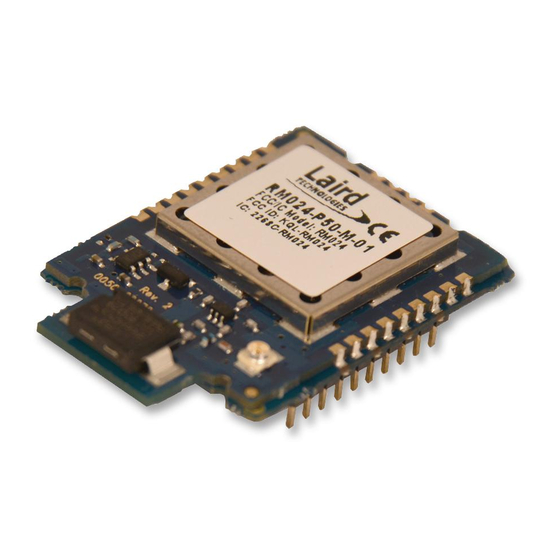
Laird RM024 Hardware Integration Manual
Ramp wireless module
Hide thumbs
Also See for RM024:
- User manual (62 pages) ,
- Hardware integration manual (24 pages) ,
- User manual (25 pages)
Table of Contents
Advertisement
Quick Links
Advertisement
Table of Contents

Summary of Contents for Laird RM024
- Page 1 Hardware Integration Guide RM024 – RAMP Wireless Module Version 3.4...
- Page 2 N. Zach Hogya Converted to new template. General edits. 24 Feb 2016 Updates to antenna information. Daniel Waters Americas: +1-800-492-2320 Embedded Wireless Solutions Support Center: Europe: +44-1628-858-940 http://ews-support.lairdtech.com Hong Kong: +852 2923 0610 www.lairdtech.com/ramp © Copyright 2015 Laird. All Rights Reserved...
-
Page 3: Table Of Contents
FCC/IC Requirements for Modular Approval ....................... 16 CE Requirements for Modular Approval ......................19 Related Documents and Files ..........................19 Americas: +1-800-492-2320 Embedded Wireless Solutions Support Center: Europe: +44-1628-858-940 http://ews-support.lairdtech.com Hong Kong: +852 2923 0610 www.lairdtech.com/ramp © Copyright 2015 Laird. All Rights Reserved... -
Page 4: Ramp Modules
16 million clients to be addressed and communicating within the network. The RM024 RAMP module improves upon Laird’s 2.4 GHz RAMP predecessors by lowering power consumption through the use of three different sleep mode options, an improved link budget, the ability for close proximity operation at low power, and the inclusion of a switchable antenna output (RM024-xxxx-M-yy versions only). -
Page 5: Detailed Specification
26.7 mm x 39.6 mm x 11.3 mm (1.05” x 1.56” x 0.44”) Dimensions Pluggable-U.FL Dimensions 26.7 mm x 33 mm x 10.6 mm (1.05” x 1.29” x 0.42”) Americas: +1-800-492-2320 Embedded Wireless Solutions Support Center: Europe: +44-1628-858-940 http://ews-support.lairdtech.com Hong Kong: +852 2923 0610 www.lairdtech.com/ramp © Copyright 2015 Laird. All Rights Reserved... -
Page 6: Pin Definitions
Low during normal operation. GIO_4 Generic Input Reset – Controlled by the RM024 for power-on reset if left unconnected. After a stable power-on µP_Reset reset, a logic low pulse resets the transceiver. When logic Low, the transceiver interprets CMD/Data incoming OEM host data as command data. -
Page 7: Input Characteristics
20 mA GO_0 GO_1 2.5 v 3.3 v 0.4 v 20 mA 4 mA PWM_Output 3.3 v Americas: +1-800-492-2320 Embedded Wireless Solutions Support Center: Europe: +44-1628-858-940 http://ews-support.lairdtech.com Hong Kong: +852 2923 0610 www.lairdtech.com/ramp © Copyright 2015 Laird. All Rights Reserved... -
Page 8: Block Diagram
600 ms 1700 ms interference could extend the maximum time indefinitely. Hop Period In Range 13.19 ms Americas: +1-800-492-2320 Embedded Wireless Solutions Support Center: Europe: +44-1628-858-940 http://ews-support.lairdtech.com Hong Kong: +852 2923 0610 www.lairdtech.com/ramp © Copyright 2015 Laird. All Rights Reserved... -
Page 9: Rf Hop Frame
Read Flash RF Hop Frame The RM024 hops every 13.19 milliseconds and can be configured for two different RF data rates to provide options for range or throughput. During each hop, the RM024 reserves a certain amount of time for overhead such as the synchronization beacon, internal messaging, and user data transmission. -
Page 10: Hardware Interface
RXD and TXD The RM024 accepts 3.3 VDC TTL level asynchronous serial data from the OEM host via the RXD pin. Data is sent from the transceiver, at 3.3 volt levels, to the OEM host via the TXD pin. Pins should be left floating or high when not in use. -
Page 11: Mechanical Considerations
ONSIDERATIONS Mechanical Drawing The pluggable versions of the RM024 consist of the surface mount RM024 on a pluggable adapter board. RM024 –C versions, which only feature an U.FL connector and no integrated antenna, are the same dimensions as in the mechanical drawings below... - Page 12 RM024 – RAMP Wireless Module Hardware Integration Guide Figure 3: RM024 mechanical drawings Americas: +1-800-492-2320 Embedded Wireless Solutions Support Center: Europe: +44-1628-858-940 http://ews-support.lairdtech.com Hong Kong: +852 2923 0610 www.lairdtech.com/ramp © Copyright 2015 Laird. All Rights Reserved...
- Page 13 RM024 – RAMP Wireless Module Hardware Integration Guide Figure 4: RM024 mechanical drawings The pluggable RM024 uses a single row header with two mil spacing. The Mill Max 831-43-010-10-001000 is used on the RM024 development kit as a mating connector. Americas: +1-800-492-2320...
- Page 14 RM024 – RAMP Wireless Module Hardware Integration Guide Figure 5: Moisture Content Warning Americas: +1-800-492-2320 Embedded Wireless Solutions Support Center: Europe: +44-1628-858-940 http://ews-support.lairdtech.com Hong Kong: +852 2923 0610 www.lairdtech.com/ramp © Copyright 2015 Laird. All Rights Reserved...
-
Page 15: Reflow Parameters
EFLOW ARAMETERS Laird’s surface mount modules are designed to be easily manufactured, including reflow soldering to a PCB. Ultimately, it is the responsibility of the customer to choose the appropriate solder paste and to ensure oven temperatures during reflow meet the requirements of the solder paste. Laird’s surface-mount modules conform to J-STD-020D1 standards for reflow temperatures. -
Page 16: Ordering Information
RM024-P10-M-30 Pluggable 10 mW (CE) U.FL or Chip RM02410M30 Developer Kit Part Number Description RM024 Developer Kit, Pluggable, 3.3V TTL Serial, 10 mW, Multiple Antennas, DVK-RM024-CE CE Approved DVK-RM024-FCC RM024 Developer Kit, Pluggable, 3.3V TTL Serial, 125mW, Multiple Antenna EGULATORY... - Page 17 RM024 – RAMP Wireless Module Hardware Integration Guide Antenna Information The RM024 family is designed to operate with the antennas listed below and a maximum gain of 9 dBi. The required antenna impedance is 50 ohms. Manufacturer Manufacturer Part Gain (dBi)
- Page 18 However, the type size for the text is not required to be larger than eight pt. CAUTION: The OEM should have their device which incorporates the RM024 tested by a qualified test house to verify compliance with FCC Part 15 Subpart B limits for unintentional radiators. WARNING: This device has been tested with an U.FL connector and the antennas listed in the table above.
-
Page 19: Ce Requirements For Modular Approval
Antennas listed in this table have been test with the RM024. ELATED OCUMENTS AND ILES Additional RM024 technical documents and software downloads are available from the Laird RM024 product page under the Documentation tab and Software Downloads tabs. Americas: +1-800-492-2320...


Need help?
Do you have a question about the RM024 and is the answer not in the manual?
Questions and answers