Laird RM024 User Manual
Ramp wireless module
Hide thumbs
Also See for RM024:
- User manual (48 pages) ,
- Hardware integration manual (24 pages) ,
- Hardware integration manual (19 pages)

Related Manuals for Laird RM024


Summary of Contents for Laird RM024
- Page 1 RAMP Wireless Module RM024 User Manual Version 2.3 Americas: +1-800-492-2320 Option 2 Europe: +44-1628-858-940 Hong Kong: +852-2923-0610 www.lairdtech.com/wireless Arrow.com. Downloaded from...
- Page 2 RM024 User Manual Version 2.3 EVISION ISTORY Rev. Revision Date Description Initial Version Added firmware changes, updated the name of the Force 9600 Pin, removed old references to LT2510 part numbers, added new information on cyclic sleep and Antenna Switch Override. Added a table under Max Power and a table for the Set Max Power command.
-
Page 3: Table Of Contents
Overview ................................48 Upgrading Via Windows OEM Configuration Utility .................... 48 Upgrading FW Commands ..........................49 Command Descriptions ............................49 Process to Manually Upgrade RM024 ........................ 51 API Operation ............................52 API Send Data Complete ............................ 52 API Receive Packet ............................. 52 API Transmit Packet ............................ -
Page 4: Ramp Modules
Overview The RM024 RAMP module is based on Laird Technologies LT2510 core technology, enhanced with a new RF front end for improved sleep, improved link budget and a switchable antenna output. The RM024 is available... -
Page 5: Detailed Specifications
RM024 User Manual Version 2.3 Detailed Specifications Table 1: Detailed Specifications ENERAL Form Factor SMD-ANT+U.FL, Pluggable-ANT+U.FL, SMD-U.FL, Pluggable-U.FL Antenna External antenna through U.FL connector or dual antenna with integrated antenna and U.FL Serial Interface Data Rate Baud rates from 1200 bps to 460800 bps. Non-standard baud rates are also supported. -
Page 6: Pin Definitions
Low during normal operation. GIO_4 Generic Input RESET – Controlled by the RM024 for power-on µP_Reset reset if left unconnected. After a stable power-on reset, a logic Low pulse will reset the transceiver. When logic Low, the transceiver interprets CMD/Data incoming OEM Host data as command data. -
Page 7: Input Characteristics
RM024 User Manual Version 2.3 SMT Pin Pluggable Pin Type Signal Name Functions When logic Low, the client is in range and In Range synchronized with a server. This will always be Low on a server. Request to Send. Floats high if left unconnected. -
Page 8: Block Diagram
U.FL DE/RE Transmitter Output Buffer Serial UART Receiver RF Switch Input Buffer EEPROM Integrated Antenna Figure 1: Block Diagram of RM024 Timing Specifications Table 5: Timing Specifications Parameter Server/Client Min. Typ. Max. Notes Power on to 5 ms 10 ms... -
Page 9: Rf Hop Frame
RF Hop Frame The RM024 hops every 13.19 ms and can be configured for two different RF data rates to provide options for range or throughput. During each hop, the RM024 reserves a certain amount of time for overhead, such as the synchronization beacon, internal messaging, and user data transmission. -
Page 10: Hardware Interface
RXD and TXD The RM024 accepts 3.3 VDC TTL level asynchronous serial data from the OEM Host via the RXD pin. Data is sent from the transceiver, at 3.3 V levels, to the OEM Host via the TXD pin. Pins should be left floating or high when not in use. - Page 11 RM024 User Manual Version 2.3 GO_0/Hop_Frame The Hop Frame indicator functionality is disabled by default and controlled by the Control 1, Bit-6 EEPROM Setting. When enabled, this pin transitions logic Low at the start of a hop and transitions logic High at the completion of a hop.
-
Page 12: Theory Of Operation
Adjustable RF Data Rate The RM024’s RF data rate can be adjusted to provide a trade-off between throughput and range. Table 6: RM024 RF Data Rate... -
Page 13: Modes Of Operation
Transparent Mode When operating in transparent mode, the RM024 can act as a direct serial cable replacement in which RF data is forwarded over the serial interface and vice versa. In transparent mode, the radio needs to be programmed with the MAC address of the desired recipient. The destination address can be programmed permanently or on-the-fly. -
Page 14: Serial Interface Baud Rate
Minimum Interface Timeout = _______ Baud Rate Tips: The RM024 supports a majority of standard as well as non-standard baud rates. To select a standard baud rate, use the value shown for EEPROM address 0x42 in Table 7. To enable a non-standard baud rate, program EEPROM address 0x42 (Custom Baud Enable) to 0xE3 and then use the equation above to solve for BAUD_M and BAUD_E. -
Page 15: Interface Timeout/Rf Packet Size
RM024 User Manual Version 2.3 Interface Timeout/RF Packet Size Interface Timeout Interface timeout specifies a maximum byte gap between consecutive bytes. When that byte gap is exceeded, the bytes in the transmit buffer are processed as a complete packet. Interface timeout (EEPROM address 0x58), in conjunction with the RF packet size, determines when a buffer of data is sent out over the RF as a complete RF packet, based on whichever condition occurs first. -
Page 16: Flow Control
RXD Data Buffer and CTS As data is sent from the OEM host to the radio over the serial interface, it is stored in the RM024’s buffer until the radio is ready to transmit the data packet. The radio waits to transmit the data until one of the... -
Page 17: Radio Configurations
TXD Data Buffer and RTS As data to be forwarded to the OEM Host accumulates, it is stored in the RM024’s outgoing buffer until the radio is ready to begin sending the data to the OEM Host. Once the data packet has been sent to the Host over the serial interface, it will be removed from the buffer and the radio will begin processing the next data packet in the buffer. - Page 18 RM024 User Manual Version 2.3 Auto Channel (EEPROM 0x56, bit 3) To allow for more flexible network configurations, Auto Channel can be enabled in clients to allow them to automatically synchronize with the first server they detect, regardless of channel number.
- Page 19 RM024 User Manual Version 2.3 further broadcast attempts. The received packet is only sent to the OEM host if it is received free of errors. Because broadcast packets have no RF acknowledgement, each packet is transmitted the number of times specified by Broadcast Attempts.
- Page 20 RM024 User Manual Version 2.3 Legacy RSSI (EEPROM 0x45, bit 2) RSSI (Received Signal Strength Indicator) is a measure of how well the receiving radio is able to hear the transmitting radio. By default, RSSI is reported in 2’s complement format; therefore, values range from 0x80 - 0x7F.
- Page 21 RM024 User Manual Version 2.3 0x4E). Any changes to the Digital Inputs that occur while a utility retransmission is occurring are not transmitted unless the change persists until all utility retries have been sent or an acknowledge was received. Therefore, this feature should only be used for slow-moving changes that occur less than the time it takes to expend all retries.
- Page 22 RM024 User Manual Version 2.3 RF Channel Number (EEPROM 0x40) This product uses FHSS (Frequency Hopping Spread Spectrum) protocol in which the transceiver communicates using frequency “bins” spaced throughout the frequency band. Therefore, RF Channel Number specifies a unique pseudo-random hopping sequence.
- Page 23 RM024 User Manual Version 2.3 Address 0x68, Bit Input Output Bit 2 set GIO_7 GIO_3 Bit 3 set CMD/Data GIO_2 Bit 4 set Bit 5 set Bit 6 clear, Bit 7 clear All I/O are Outputs Bit 6 set, Bit 7 clear...
- Page 24 RM024 User Manual Version 2.3 Wake Count (EEPROM 0xCF) Time in number of hops (13.19 ms each) to stay awake during cyclic sleep. This counter is an inactivity counter, therefore the counter is reset as long as the device continues to transmit packets over the RF interface.
- Page 25 RM024 User Manual Version 2.3 Vendor ID The Vendor ID, like the System ID, can be used to uniquely identify a network. Radios with the Vendor ID set, only communicate with other radios with the same set Vendor ID. The Vendor ID is a protected EEPROM parameter and its value cannot be read. It can only be written once.
-
Page 26: Eeprom Parameters
EEPROM P ARAMETERS The RM024 utilizes a server-client network architecture to synchronize the frequency hopping. Each network must have one radio configured as a server and all other radios configured as clients. When a radio is configured as a server, it transmits a beacon at the beginning of each hop. Radios configured as clients default to a receive mode where they are scanning the available frequencies listening for a beacon from a server in their network. - Page 27 Details Profile Rate of Hops Description 0x00 Valid for international use. Can Kbps be selected on any RM024 product 0x01 For FCC Markets only. This is the Kbps default settings for the RM024- x125-x models 0x03 This is the default setting for...
- Page 28 RM024 User Manual Version 2.3 Parameters EEPROM Length Range Default Description Address (Bytes) 1 = Enable (Turns off Hop Frame Pin) bit-5: Reserved bit-4: Auto Destination 0 = Use Destination Address 1 = Use Auto Destination bit-3: Client Auto Channel...
- Page 29 RM024 User Manual Version 2.3 Parameters EEPROM Length Range Default Description Address (Bytes) 0 = Disable 9600 Boot Option 1 = Enable 9600 Boot Option Interface 0x58 0x02- 0x03 Specifies a byte gap timeout, used in Timeout conjunction with RF packet size to...
- Page 30 RM024 User Manual Version 2.3 Parameters EEPROM Length Range Default Description Address (Bytes) Settings are: Remote I/O 0x60 0x00-0xFF 0x00 bit-7: Use Pairs Control 0 = Disable pairs and allows radio I/O already set in bits 5-0 to be all input...
- Page 31 RM024 User Manual Version 2.3 Parameters EEPROM Length Range Default Description Address (Bytes) Sleep 0x61 0x00- 0x00 Used to modify sleep settings Control 0xFF Settings are: bit-7: Reserved. Do not modify bit-6: Reserved. Do not modify bit-5: Reserved. Do not modify bit-4: Reserved.
- Page 32 RM024 User Manual Version 2.3 Parameters EEPROM Length Range Default Description Address (Bytes) 0 = Disable Unintended report 1 = Reports RSSI on packets not intended for this transceiver bit-2: Broadcast Report 0 = Disable Broadcast Report 1 = Reports RSSI on Broadcast packets...
- Page 33 RM024 User Manual Version 2.3 Parameters EEPROM Length Range Default Description Address (Bytes) User 0xA0 0x00-0xFF 0xFF This memory is reserved host memory and Memory is never used by the radio. The host is free to use this memory as desired and it is only modified when instructed to do so by the host.
- Page 34 RM024 User Manual Version 2.3 Parameters EEPROM Length Range Default Description Address (Bytes) 1-4 packet times: 0x03 1-8 packet times: 0x07 1-16 packet times: 0x0F 1-32 packet times: 0x1F 1-64 packet times: 0x3F 1-128 packet times: 0x7F 1-256 packet times: 0xFF...
- Page 35 RM024 User Manual Version 2.3 Parameters EEPROM Length Range Default Description Address (Bytes) bit 2: GIO_3 Initialize 0 = GIO_3 is initialized Low at boot 1 = GIO_3 is initialized High at boot bit 1: GIO_1 Initialize 0 = GIO_1 is initialized Low at boot...
-
Page 36: Configuring The Rm024
RF packets are not queued and are not sent to the host immediately. AT Commands sent to the RM024 must still adhere to the interface guidelines specified by the Interface Timeout and RF Packet Size. For this reason, standard terminal emulators, such as HyperTerminal, cannot be used to configure the RM024. - Page 37 RM024 User Manual Version 2.3 Table 11: Config and Diagnostic Commands Command Name Command (all bytes in hex) Return (all bytes in hex) TILITY OMMANDS Enter AT Command Mode <0x41> <0x54> <0x2B> <0x2B> <0xCC> <0x43> <0x4F> <0x4D> <0x2B> <0x0D> Exit AT Command Mode <0xCC>...
-
Page 38: Utility Commands
RM024 User Manual Version 2.3 Command Name Command (all bytes in hex) Return (all bytes in hex) Write Flash <0xCC><0xC4><Start_H><Start_L> <0xCC><0xC4><Result> <Length_H><Length_L><Data> <Start_H><Start_L> Decrypt New Image <0xCC><0xC5> <0xCC><0xC5><Data> Erase Flash <0xCC><0xC6> <0xCC><0xC6> Read Flash <0xCC><0xC9><Start_H><Start_L> <0xCC><0xC9><Result><Start_H> <Length_H><Length_L> <Start_L><Length_H> <Length_L><Data> Set Vendor ID <0xCC>... - Page 39 RM024 User Manual Version 2.3 PM3: The module can only be awakened by the Sleep Interrupt pin (Force 9600). The sleep timer is not active in PM3 and the bytes controlling the timer (RES, Timer_H, Timer_L) are disregarded and can be omitted from the command as well.
-
Page 40: Status Commands
RM024 User Manual Version 2.3 Status Commands Check Status Registry In firmware v2.2 and forward, the Status Registry contains error codes which may be useful for the OEM to note. Note: Sleep crystal is only checked on boot. Wake Event is written every time the module wakes from sleep. -
Page 41: Command Descriptions
RM024 User Manual Version 2.3 Bin Analyzer The Bin Analyzer is a powerful command for understanding the link conditions between two radios over the entire frequency hopping spectrum. The Bin Analyzer causes the local radio to send an RSSI request packet to the radio specified in the Destination Address field. - Page 42 RM024 User Manual Version 2.3 Change Server/Client The OEM host issues this command to set the module as a server or a client on-the-fly. Command: <0xCC> <0x03><Data> Number of Bytes Returned: Response: <0xCC> <Firmware Version><Status> Parameter Range: <Data> 0x02 = Server 0x03 = Client <Firmware>...
- Page 43 RM024 User Manual Version 2.3 Command: <0xCC> <0x0A> <Location> Number of Bytes Returned: Response: <0xCC> <Value> Parameter Range: <Location>: [Dependant of parameter] <Value>: 0x00-0xFF Write IRAM This command is used to change the IRAM contents. The IRAM contains the active (in memory) copy of the EEPROM parameters.
- Page 44 RM024 User Manual Version 2.3 Write Destination Address The OEM host issues this command to the transceiver to change the destination address. Command: <0xCC> <0x10> <MAC1> <MAC2> <MAC3> Number of Bytes Returned: Response: <0xCC> <MAC1> <MAC2i> <MAC3> Parameter Range: 0x00 - 0xFF corresponding to the 3 LSBs of the destination MAC Address.
- Page 45 RM024 User Manual Version 2.3 Write API Control The OEM host issues this command to write the API Control byte to enable or disable the API features. Command: <0xCC> <0x17> <API Control> Number of Bytes Returned: Response: <0xCC> <API Control>...
- Page 46 The OEM host issues this command to adjust the maximum output power. Max Power settings are typical and can vary by 2 dBm. The maximum output power never exceeds +18 dBm for RM024-x50-x or +21dBm for RM024-x125-x. Command: <0xCC> <0x25><Max Pwr>...
- Page 47 RM024 User Manual Version 2.3 RM024-x125-x RM024-x50-x 0x00: 21 dBm typical 0x00: 17dBm typical 0x01: 17 dBm typical 0x01: 14 dBm typical 0x02: 14 dBm typical 0x02: 11 dBm typical 0x03: 11 dBm typical 0x03: 8 dBm typical Antenna Select Command The OEM host issues this command to select the antenna port.
-
Page 48: Serial Firmware Upgrades
PC, but for embedded applications it may be necessary for the OEM to program the FW upgrade through a microcontroller. Upgrade of the FW over the air is not supported on the RM024. The firmware upgrade procedure will not affect the radio EEPROM settings except to update the version number. -
Page 49: Upgrading Fw Commands
RM024 User Manual Version 2.3 Figure 3: Upgrading firware in Laird Configuration Utility Upgrading FW Commands These commands are used to upgrade the FW on the RM024; these commands are only valid on FW version 1.3 and above. Command Descriptions Write Flash This command is used to write an encrypted binary file to the reserve flash. - Page 50 RM024 User Manual Version 2.3 Parameter Range: <StartAddress[1,0]>: 0x00 0x00 – 0x3B 0xFF <Length[1,0]>: 0x00 0x01 – 0x00 0xFF <BytesToWrite>: The actual data being written <Result> 0x00 No Error 0x03 Command Timed Out 0x06 Bounds Exceeded (Start Address + Length is outside the...
-
Page 51: Process To Manually Upgrade Rm024
<Data>: Contents of Flash Process to Manually Upgrade RM024 By using the above AT commands, it is possible to upgrade a RM024 over the UART from a microcontroller or other device. To do this, follow these basic steps: Make sure the OEM host has a copy of an encrypted binary firmware upgrade files. -
Page 52: Api Operation
API O PERATION API Operation is a powerful alternative to the default transparent operation of the RM024 and provides dynamic packet accounting abilities to the OEM host without requiring extensive programming by the OEM host. API operation utilizes specific packet formats. The API features can be used in any combination that suits the OEM’s specific needs and can be different between radios operating on the same network. -
Page 53: Api Transmit Packet
RM024 User Manual Version 2.3 Figure 5: Receive API Packet Format API Transmit Packet API Transmit Packet is a powerful API mode that allows the OEM host to send data to a single or multiple (via Broadcast) transceivers on a packet-by-packet basis. This can be useful for many applications including polling and mesh networks. -
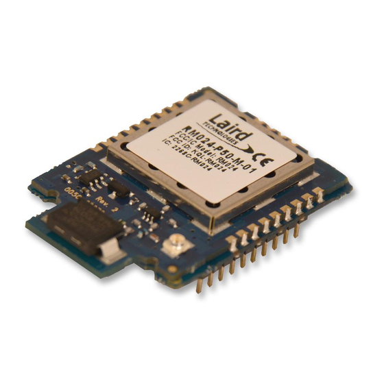
Page 54: Mechanical Considerations
ONSIDERATIONS Mechanical Drawing The pluggable versions of the RM024 consist of the surface mount RM024 on a pluggable adapter board. RM024 –C versions which only feature an U.FL connector and no integrated antenna are the same dimensions as below with the stub for the antenna connector removed. For the surface mount units, this means the module is 32.38 mm long. - Page 55 RM024 User Manual Version 2.3 Figure 8: Form Factor: Pluggable RM024 (RM024-PXXX-M-01) CONN-GUIDE-RAMP24-0413 Americas: +1-800-492-2320 Option 2 Europe: +44-1628-858-940 Hong Kong: +852-2923-0610 www.lairdtech.com/wireless Arrow.com. Arrow.com. Arrow.com. Arrow.com. Arrow.com. Arrow.com. Arrow.com. Arrow.com. Arrow.com. Arrow.com. Arrow.com. Arrow.com. Arrow.com. Arrow.com. Arrow.com. Arrow.com. Arrow.com.
- Page 56 RM024 User Manual Version 2.3 The Pluggable RM024 uses a single row header with 2 mil spacing. The Mill Max 831-43-010-10-001000 is used on the RM024 development kit as a mating connector. Figure 9: Moisture Content Warning CONN-GUIDE-RAMP24-0413 Americas: +1-800-492-2320 Option 2...
-
Page 57: Ordering Information
50 mW (CE) u.FL Jack RM02450C01 RM024-P50-M-01 Pluggable 50 mW (CE) Chip Ant RM02450M01 Table 13: RM024 Development Kits Part Numbers Part # Description Regulatory Full Development Kit with one USB Eval Board and one RS-232 FCC/IC RM024-S125-C-01 Eval Board containing the... -
Page 58: Regulatory Information
*Last two slots "XX" in Part # are used for custom setups. Can be values 01-99, aa-zz Antenna Information RM024 family has been designed to operate with the antennas listed below and having a maximum gain of 9 dBi. The required antenna impedance is 50 ohms. - Page 59 separation distance of at least 20 centimeters is normally maintained between the transmitter's radiating structures and the body of the user or nearby persons. The RM024 is fully modular approved for mobile and fixed applications Reference FCC Part 2.1091 for further details on mobile devices.
- Page 60 Version 2.3 CAUTION: Any changes or modifications not expressly approved by Laird Technology could void the user’s authority to operate the equipment. NOTE: This equipment has been tested and found to comply with the limits for a Class B digital device, pursuant to Part 15 of the FCC Rules.
-
Page 61: Rm024 Firmware History
*These antennas are only approved for use with the RM024-P50-C-01 in UV Applications RM024 Firmware History This section will detail key differences between firmware releases of the RM024. The previous sections of the User Manual only deal with the latest version. Some features and default settings have changed from one firmware to the next. - Page 62 This mode permits the user to select which port is to be used. Note that, while the software allows this mode to be used on any RM024 product, it does not verify that the selected antenna option is present on the hardware platform.
Need help?
Do you have a question about the RM024 and is the answer not in the manual?
Questions and answers