Table of Contents
Advertisement
Quick Links
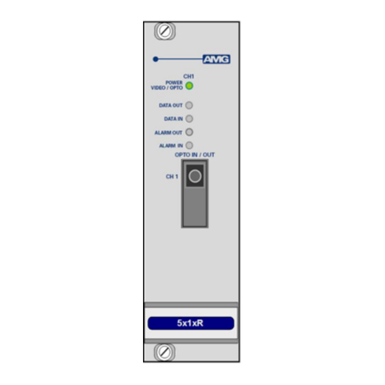
Receive Unit with one Bi-directional Data Channel and one
Bi-directional Alarm for a Singlemode Fibre Link
The AMG5514R is a rackmount receive unit designed to transmit and receive 1 data signal plus 1 Bi-
directional alarm over one Singlemode optical fibre.
The AMG5514R is designed to plug into an AMG2009 or AMG2015 subrack, which in turn fits into a
19" rack system.
The AMG5514R is designed to operate with an AMG5513 / AMG5513R transmit unit in a point to
point configuration. The R suffix in the partno. indicates a rackmount configuration.
AMG Systems Ltd. reserves the right to make changes to this
document without notice. The information herein is believed to
be accurate. No responsibility is assumed by AMG for its use.
AMG5514R
Instruction Manual
Page 1 of 8
AMG5514R Instruction Sheet D17366-
00.doc
Advertisement
Table of Contents

Related Manuals for AMG AMG5514R


Summary of Contents for AMG AMG5514R
- Page 1 Receive Unit with one Bi-directional Data Channel and one Bi-directional Alarm for a Singlemode Fibre Link The AMG5514R is a rackmount receive unit designed to transmit and receive 1 data signal plus 1 Bi- directional alarm over one Singlemode optical fibre.
-
Page 2: Table Of Contents
Safety 8 Maintenance and Repair 8 AMG Systems Ltd. reserves the right to make changes to this Page 2 of 8 AMG5514R Instruction Sheet D17366- document without notice. The information herein is believed to 00.doc be accurate. No responsibility is assumed by AMG for its use. -
Page 3: Introduction
Optical Connection The AMG5514R connections are illustrated in the following example which shows an AMG5513 transmit unit together with an AMG5514R rackmount receive unit configured as a single channel point to point system. AMG Systems Ltd. reserves the right to make changes to this... -
Page 4: Connections
Alarm input ........... Contact Closure pull-up is 330R to +3V3 Alarm Output ........Solid-state Relay, maximum 150mA at 125Vac/dc, Ron < 6.5Ω AMG Systems Ltd. reserves the right to make changes to this Page 4 of 8 AMG5514R Instruction Sheet D17366- document without notice. -
Page 5: Front Panel Indicators
ALARM OUT ........Green Alarm ON / Contacts closed. Alarm OFF / Contacts open. AMG Systems Ltd. reserves the right to make changes to this Page 5 of 8 AMG5514R Instruction Sheet D17366- document without notice. The information herein is believed to 00.doc... -
Page 6: Data And Alarm Channel Configuration
RS-485 bus high (+5 volts) and the other arm low (0 volts) using high value resistors within the third party equipment. In order to ensure that the AMG equipment detects a tri-state condition, then these resistors should have a value above 5kΩ. If the third party bias resistors are less the 750Ω... -
Page 7: Data Interface Connections
Note: (A) or (B) in brackets in the above table refers to RS-485 / RS-422 data specification. Alarm Channel Configuration The AMG5514R provides one bi-directional alarm output / contact closure input. The alarm input is typically connected to a contact closure switch. An ALARM IN+ input incorporates a 330R pull-up resistor to the internal +3V3 supply. -
Page 8: Physical Information Dimensions
There are no user serviceable parts within AMG products. See unit data sheet for full specification. In case of problem or failure, please call your local support centre or contact: AMG Systems Ltd. at 3 The Omega Centre, Stratton Business Park, Biggleswade, Beds., SG18 8QB, UK.
Need help?
Do you have a question about the AMG5514R and is the answer not in the manual?
Questions and answers