Table of Contents
Advertisement
Quick Links
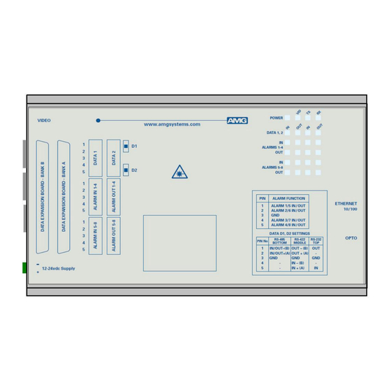
Data Receive Unit with 2 Bi-directional Data Channels, 14
Bi-directional Audio Channels, 2 Echelon FTT-10A Data
Channels and 8 Bi-directional Alarms plus Ethernet for a
The AMG5904A966B9 is a standalone data receive unit designed to transmit and receive 2 data
channels, 14 audio channels, 2 Echelon FTT-10A data channels and 8 bi-directional alarms over one
Singlemode optical fibre. It also provides full duplex 100BASE-TX Ethernet connectivity.
The AMG5904A966B9 is designed to be powered using an AMG2003 standalone power supply.
The AMG5904A966B9 is designed to operate with an AMG5903A966B9 standalone or
AMG5903A966B9G rackmount data transmit unit in a point to point configuration.
AMG Systems Ltd. reserves the right to make changes to this
document without notice. The information herein is believed to
be accurate. No responsibility is assumed by AMG for its use.
Singlemode Fibre Link
AMG5904A966B9
Instruction Manual
Page 1 of 12
AMG5904A966B9 Instruction Sheet
D22153-00.doc
Advertisement
Table of Contents

Related Manuals for AMG AMG5904A966B9


Summary of Contents for AMG AMG5904A966B9
- Page 1 Channels and 8 Bi-directional Alarms plus Ethernet for a Singlemode Fibre Link The AMG5904A966B9 is a standalone data receive unit designed to transmit and receive 2 data channels, 14 audio channels, 2 Echelon FTT-10A data channels and 8 bi-directional alarms over one Singlemode optical fibre.
-
Page 2: Table Of Contents
Physical Information Dimensions ............................12 Mounting Details ..........................12 Safety Maintenance and Repair AMG Systems Ltd. reserves the right to make changes to this Page 2 of 12 AMG5904A966B9 Instruction Sheet document without notice. The information herein is believed to D22153-00.doc... -
Page 3: Introduction
Ethernet connectivity is also provided between the two units. Optical Connection The AMG5904A966B9 connections are illustrated in the following example which shows an AMG5903A966B9G rackmount data transmit unit together with an AMG5904A966B9 data receive unit configured as a point to point system. -
Page 4: Connections
Input impedance ........56kΩ / 600Ω. Each channel individually selected using DIL switch on front panel Output impedance .......600Ω Frequency response ......10Hz to 20KHz AMG Systems Ltd. reserves the right to make changes to this Page 4 of 12 AMG5904A966B9 Instruction Sheet document without notice. The information herein is believed to D22153-00.doc... -
Page 5: Echelon Ftt-10A Data Channel Connection
Ethernet Data Connector ....RJ45 Interface..........Auto MDI/MDIX 100BASE-TX Ethernet Data Rate......Maximum 100Mb/s full duplex AMG Systems Ltd. reserves the right to make changes to this Page 5 of 12 AMG5904A966B9 Instruction Sheet document without notice. The information herein is believed to D22153-00.doc... -
Page 6: Front Panel Indicators
> 0dBm (overload at +6dBm) audio not present or < -40dBm This represents the audio signals being received from the optical fibre. AMG Systems Ltd. reserves the right to make changes to this Page 6 of 12 AMG5904A966B9 Instruction Sheet document without notice. -
Page 7: Alarm Leds
Alarm ON / Contacts closed. Alarm OFF / Contacts open. Echelon FTT-10A Data LEDs Data type depends on AMG system: RS-232, RS-422, RS-485, 20mA,TTL, or FTT-10A Data Present IN ........Green Data channel present but not transmitting Data channel transmitting Data channel not present or no connection IN corresponds to the data signals being transmitted onto the optical fibre. -
Page 8: Data And Alarm Channel Configuration
RS-485 bus high (+5 volts) and the other arm low (0 volts) using high value resistors within the third party equipment. In order to ensure that the AMG equipment detects a tri-state condition, then these resistors should have a value above 5kΩ. If the third party bias resistors are less the 750Ω... -
Page 9: Alarm Channel Configuration
RS-232 (no termination), RS-422 (120Ω) or RS-485 (120Ω). Alarm Channel Configuration The AMG5904A966B9 provides 8 bi-directional contact closure inputs / alarm outputs. Each ALARM IN input is via an internal 10kΩ series resistor with a 47kΩ pull-up resistor to the internal +3V3 supply. -
Page 10: Alarm Interface Connections
The GND connection associated with any Data signal signal should be connected to one of the GND pins available on the 37way D-type connector. These GND inputs are common to all audio / data channels. AMG Systems Ltd. reserves the right to make changes to this Page 10 of 12 AMG5904A966B9 Instruction Sheet document without notice. -
Page 11: Data And Audio Connections
Bank A : Channels 1-6 are Audio and Channels 7 & 8 are FTT-10A Data. Bank B : Channels 1-8 are Audio. AMG Systems Ltd. reserves the right to make changes to this Page 11 of 12 AMG5904A966B9 Instruction Sheet document without notice. -
Page 12: Physical Information
Weight..........1000grams Mounting Details The AMG unit is supplied with a clip-on mounting bracket which should be attached to a panel or wall using 2 off 4.0mm screws, see diagram on page 1 for dimensions. The unit is clipped into the mounting bracket, and is then held firmly in position.
Need help?
Do you have a question about the AMG5904A966B9 and is the answer not in the manual?
Questions and answers