Table of Contents
Advertisement
Quick Links
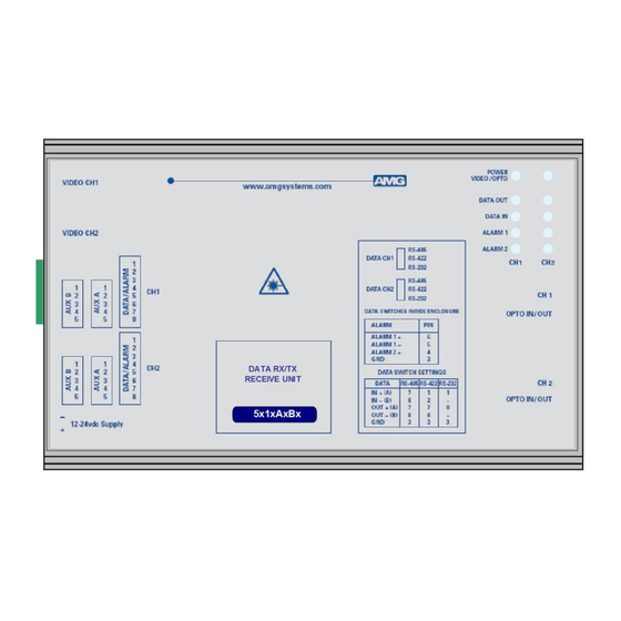
Receive Unit with one Bi-directional Data Signal, two Bi-
directional Alarms and one Bi-directional Audio Channel
The AMG5514A5B9 is a standalone receive unit designed to transmit & receive 1 data signal, 2 Bi-
directional alarms plus 1 Bi-directional audio channel over one Singlemode optical fibre.
The AMG5514A5B9 is designed to be powered using an AMG2001 standalone power supply.
The AMG5513A5B9 is designed to operate with an AMG5513A5B9 / AMG5513A5B9R transmit unit
in a point to point configuration. The R suffix in the partno. indicates a rackmount configuration.
AMG Systems Ltd. reserves the right to make changes to this
document without notice. The information herein is believed to
be accurate. No responsibility is assumed by AMG for its use.
for a Singlemode Fibre Link
AMG5514A5B9
Instruction Manual
Page 1 of 12
AMG5514A5B9 Instruction Sheet
D17370-00.doc
Advertisement
Table of Contents

Related Manuals for AMG AMG5514A5B9


Summary of Contents for AMG AMG5514A5B9
- Page 1 Alarms and one Bi-directional Audio Channel for a Singlemode Fibre Link The AMG5514A5B9 is a standalone receive unit designed to transmit & receive 1 data signal, 2 Bi- directional alarms plus 1 Bi-directional audio channel over one Singlemode optical fibre.
-
Page 2: Table Of Contents
Physical Information Dimensions ............................10 Mounting Details ..........................10 Safety Maintenance and Repair AMG Systems Ltd. reserves the right to make changes to this Page 2 of 12 AMG5514A5B9 Instruction Sheet document without notice. The information herein is believed to D17370-00.doc... -
Page 3: Introduction
Optical Connection The AMG5514A5B9 connections are illustrated in the following example which shows an AMG5513A5B9 transmit unit together with an AMG5514A5B9 standalone receive unit configured as a single channel point to point system. AMG Systems Ltd. reserves the right to make changes to this... -
Page 4: Connections
Input impedance ........10kΩ / 600Ω Output impedance ....... 600Ω Frequency response ......10Hz to 20KHz AMG Systems Ltd. reserves the right to make changes to this Page 4 of 12 AMG5514A5B9 Instruction Sheet document without notice. The information herein is believed to D17370-00.doc... - Page 5 *See appropriate section on how to remove the case for access to the data/audio switches. 1-2 – High Impedance 10kΩ 2-3 – Balanced 600Ω AMG Systems Ltd. reserves the right to make changes to this Page 5 of 12 AMG5514A5B9 Instruction Sheet document without notice.
-
Page 6: Front Panel Indicators
> 0dBm (overload at +6dBm) audio not present or < -40dBm This represents the audio signals being received from the optical fibre. AMG Systems Ltd. reserves the right to make changes to this Page 6 of 12 AMG5514A5B9 Instruction Sheet document without notice. -
Page 7: Data And Alarm Channel Configuration
RS-485 bus high (+5 volts) and the other arm low (0 volts) using high value resistors within the third party equipment. In order to ensure that the AMG equipment detects a tri-state condition, then these resistors should have a value above 5kΩ. If the third party bias resistors are less the 750Ω... -
Page 8: Data Interface Connections
Note: (A) or (B) in brackets in the above table refers to RS-485 / RS-422 data specification. Alarm Channel Configuration The AMG5514A5B9 provides 2 bi-directional contact closure inputs / alarm outputs. Each ALARM IN input is via an internal 10kΩ series resistor with a 47kΩ pull-up resistor to the internal +3V3 supply. -
Page 9: Aux. Alarm Interface Connections
600Ω. JP1/JP2 1-2 – High Impedance 10kΩ JP1/JP2 2-3 – Balanced 600Ω AMG Systems Ltd. reserves the right to make changes to this Page 9 of 12 AMG5514A5B9 Instruction Sheet document without notice. The information herein is believed to D17370-00.doc... -
Page 10: Physical Information
Weight ..........750grams Mounting Details The AMG unit is supplied with a clip-on mounting bracket which should be attached to a panel or wall using 2 off 4.0mm screws, see diagram on page 1 for dimensions. The unit is clipped into the mounting bracket, and is then held firmly in position. - Page 11 This page is intentionally blank. AMG Systems Ltd. reserves the right to make changes to this Page 11 of 12 AMG5514A5B9 Instruction Sheet document without notice. The information herein is believed to D17370-00.doc be accurate. No responsibility is assumed by AMG for its use.
- Page 12 This page is intentionally blank. AMG Systems Ltd. reserves the right to make changes to this Page 12 of 12 AMG5514A5B9 Instruction Sheet document without notice. The information herein is believed to D17370-00.doc be accurate. No responsibility is assumed by AMG for its use.
Need help?
Do you have a question about the AMG5514A5B9 and is the answer not in the manual?
Questions and answers