Emulex LP9802DC Installation And Reference Manual
Host bus adapters
Hide thumbs
Also See for LP9802DC:
- Troubleshooting and maintenance manual (23 pages) ,
- User manual (69 pages)
Table of Contents
Advertisement
Quick Links
Download this manual
See also:
User Manual
LP9802DC Installation and Reference Manual
Table of Contents
Installation
Compatibility/Prerequisites
Set Jumpers
Emulex Documentation, Drivers and Software
1
Advertisement
Table of Contents

Related Manuals for Emulex LP9802DC


Summary of Contents for Emulex LP9802DC
-
Page 1: Table Of Contents
LP9802DC Installation and Reference Manual Table of Contents Installation Compatibility/Prerequisites Set Jumpers Install HBA Attach Media Apply Power View LEDs Reference Specifications FCC and Regulatory Notices Declaration of Conformity Laser Safety... -
Page 2: Install Hba
Chapter 1 − Installation Table of Contents Compatibility/Prerequisites Set Jumpers Install HBA Attach Media Apply Power View LEDs... -
Page 3: Installation
PCI−X bus computer with a clock rate up to 133 MHz Note The LP9802DC HBA can be used only in a 3.3V signaling slot. 66 MHz, 64−bit PCI slots and 66/100/133 MHz, 64−bit PCI−X slots are 3.3V signaling slots. The LP9802DC HBA is keyed so it cannot be installed in an incorrect slot. -
Page 4: Set Jumpers
Set Jumpers The host adapter has two pairs of jumper blocks that control the host adapter's device ID. P1_JX1 & P1_JX2 control the device ID for Port 1, and P2_JX1 & P2_JX2 control the device ID for Port 2. The default device ID for both ports is F980. - Page 5 Port 2 Device ID Jumper Setting F980 JX1:1−2, JX2:2−3 1AE5 JX1:2−3, JX2:2−3 F981 JX1:2−3, JX2:1−2...
-
Page 6: Install The Host Bus Adapter Board
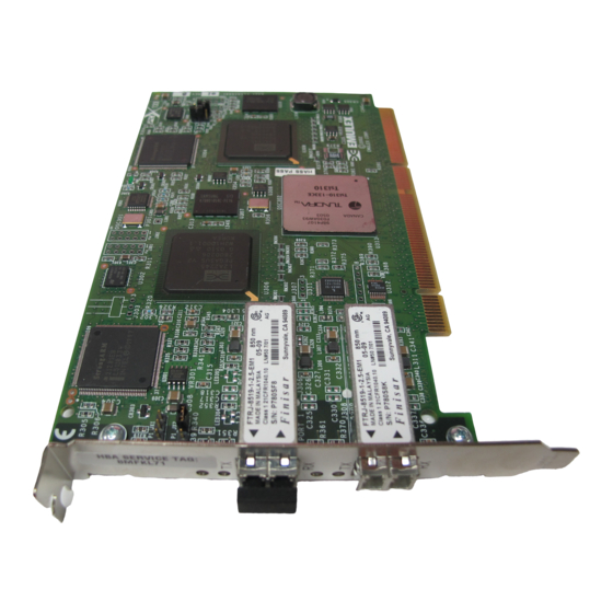
IEEE addresses. The IEEE address is used when configuring your system. The serial number is used when communicating with Emulex. All numbers are clearly marked on the board. We recommend that you record these numbers before installation. -
Page 7: Attach Media
Attach Media Note The host bus adapter will not allow normal data transmission on an optical link unless it is connected to another similar or compatible laser product (that is, multimode to multimode.) Use multimode fiber optic cable, with short−wave lasers, that adheres to the following specifications: Fiber Optic Cable Maximum Length... -
Page 8: Apply Power
Apply Power Verify that the host bus adapter is securely installed in the computer. Verify that the correct media is attached. Plug in and turn on the computer. Observe LEDs for Power On Self Test (POST) results. View LEDs A light−emitting diode (LED) is located near the top edge of the board. - Page 9 POST conditions and results are summarized in the following table. Green Yellow Slow blink (1 Fast blink (4 Flashing (irregular) Slow blink Fast blink Slow blink Slow blink Slow blink Slow blink Fast blink Slow blink Flashing State Wake−up failure (dead board). Check the 3.3v LED near the top edge of the HBA (component side).
- Page 10 Chapter 2 − Reference Table of Contents Specifications FCC and Regulatory Notices Declaration of Conformity Laser Safety...
-
Page 11: Reference
Agency Class 1 Laser Product per DHHS 21CFR (J) & EN60825−1 Approvals for UL recognized to UL1950 LP9802DC CUR recognized to CSA 22.2, No.950 Baurt−certified by TUV to EN60950 FCC Rules, Part 15, Class A Industry Canada, ICES−003, Class A... -
Page 12: Fcc And Regulatory Notices
The reader is cautioned that changes or modifications made to the equipment not expressly approved by Emulex could void the user's authority to operate this equipment. The above statement applies to products marketed in the USA This class A digital apparatus meets all requirements of the Industry Canada (IC) Interference −... - Page 13 Emulex Documentation, Drivers and Software Translation: This is a Class A product. In a domestic environment this product may cause radio interference in which case the user may be required to take adequate measures. VCCI—A Manual Notice Translation: This is a Class A product based on the standard of the Voluntary Control Council for Interference by Information Technology Equipment (VCCI).
-
Page 14: Declaration Of Conformity
Declaration of Conformity LP9802−F2/LP982−F2 (2x5 SFF models)/LP9802DC−F2 Note Changes or modifications not expressly approved by Emulex Corporation could void the user's authority to operate this equipment. This equipment complies with CISPR22/EN55022 Class A. Warning This is a class A product. In a domestic environment, this product may cause radio interference requiring the user to take adequate measures. -
Page 15: Laser Safety Notice
Gigabaud Link Modules (GLMs), Gigabit Interface Converters (GBICs), 1x9 and small form factor transceivers sold as accessories to or incorporated in Emulex LightPulse host adapters. The GLM, GBIC, 1x9 and small form factor transceiver are the primary cable connection mechanisms for any optical port on the host adapter and hub. - Page 16 In Europe, all optical GLMs, GBICs, 1x9 and small form factor transceivers sold by Emulex are certified as Class 1 laser component assemblies that conform to the requirements contained in the CENELEC (European Committee for Electrotechnical Standardization) standard EN60825−1:1994 (including amendment 11) and EN60825−2:1994.
- Page 17 Product Information GBIC 1 x 9 Transceiver Small Form Factor Transceiver The optical GLM is a single port communications card. Each communication port consists of a transmitter and receiver optical subassembly. The transmitter subassembly contains a semiconductor laser diode of gallium aluminum arsenide (GaAlAs). This material emits in the wavelength range of 770 to 860 nanometers for shortwave and 1270 to 1355 nanometers for long wave, and are commonly referred to as short wavelength (SW) or long wavelength (LW) lasers.
- Page 18 Emulex Documentation, Drivers and Software GBIC The optical GBIC is an integrated duplex data link for bi−directional communications over multimode or single mode optical fiber. Each GBIC consists of a transmitter and receiver optical subassembly. The transmitter subassembly contains a semiconductor laser emitting in the wavelength range of 770 to 860 nanometers for shortwave length GBICs and 1270 to 1355 nanometers for long wavelength GBICs.
- Page 19 Short wavelength and long wavelength GBICs allow normal data transmission on the optical link when they are connected to another compatible laser product. Short wavelength and long wavelength GBICs sold by Emulex as accessories are non−OFC devices. For non−OFC links, a compatible laser...
- Page 20 Class 1 limits. System Level Certification All GLMs and GBICs sold as accessories by Emulex or host adapters containing embedded 1x9 or small form factor transceivers are certified as Class 1 laser products within the U.S. and Class 1 laser component assemblies outside of the U.S.
Need help?
Do you have a question about the LP9802DC and is the answer not in the manual?
Questions and answers