Table of Contents
Advertisement
Quick Links
Advertisement
Table of Contents

Summary of Contents for Speco O4VFBM
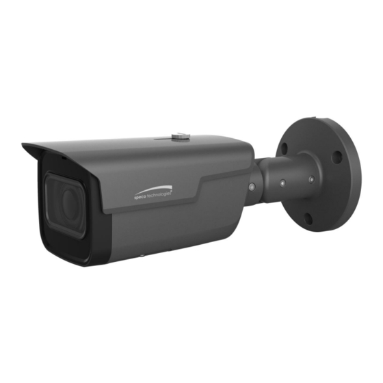
- Page 1 Quick Start Guide 4MP Motorized Vari-focal Bullet IP Camera O4VFBM Version 1.0...
- Page 2 This manual is designed to be a reference tool for your system. Please read this manual carefully before you use this series product! Should you require any technical assistance, please contact Speco Technologies Technical Support Important Safeguards and Warnings 1.Electrical safety All installation and operation here should conform to local electrical safety codes.
- Page 3 This guide is for reference only. Product, manuals and specifications may be modified without prior notice. Speco Technologies reserves the right to modify these without notice and without incurring any obligation. Speco Technologies is not liable for any loss caused by improper operation.
-
Page 4: Table Of Contents
Table of Contents 1 Physical Specifications ........................5 1.1 Device External Cable ......................5 1.2 Dimensions ..........................5 2 Device Installation ..........................6 2.1 Install SD Card .......................... 6 2.2 Fix Device ..........................7 2.3 Connect Device Cable ......................8 2.4 Adjust Device Angle ........................ -
Page 5: Physical Specifications
1 Physical Specifications 1.1 Device External Cable Note The following structure figure is for reference only. It is only used to know the functions of cable ports. Figure 1-1 Please refer to Table 1-1 for the functions of external cable and I/O port respectively. Port Port name Connector... -
Page 6: Device Installation
2 Device Installation 2.1 Install SD Card Note Please implement the step when the device is equipped with Micro SD card slot and it needs to use Micro SD card. Please cut off power before installing Micro SD card. ... -
Page 7: Fix Device
2.2 Fix Device Note The following figures are for reference only; please refer to the product for more details. Make sure the bracket installation surface can sustain at least 3X weight of the total weight of bracket and camera. Some devices do not support manual focusing lever, please refer to the real product for more ... -
Page 8: Connect Device Cable
2.3 Connect Device Cable Connect device corresponding power cable well according to requirement (optional if using power-over-ethernet (PoE), and then use insulated tape to twine the connection respectively to make it waterproof. Connect network cable to corresponding network port of the device cable according to “Install Waterproof Connector (Optional)”. -
Page 9: Adjust Device Angle
2.4 Adjust Device Angle Figure 2-4 Step 1 Use inner hex screwdriver to loosen the adjusting screw which is shown in the Figure above. Step 2 Adjust the device in all possible direction, set monitoring direction according to the application requirement. Step 3 Use inner hex screwdriver to tighten the adjusting screw. -
Page 10: Ip Scanner
3 IP Scanner 3.1 Overview IP Scanner can search for the device on the local network. Please note that only devices that are on the same subnet can be discovered. 3.2 Operation Open up IP Scanner In the device list, you can view the IP address, model number, and MAC address of each device. Select the applicable device and double click to open up the web viewer. -
Page 11: Web Operation
4 Web Operation This device supports viewing and management via a web browser on a PC. 4.1 Login and Main Interface Open the browser and input network camera address in the address bar or double click the device in IP Scanner. See Figure 4-1. Figure 4-1 The login interface is shown as below.


Need help?
Do you have a question about the O4VFBM and is the answer not in the manual?
Questions and answers