
Related Manuals for Speco O4VBW2


Summary of Contents for Speco O4VBW2
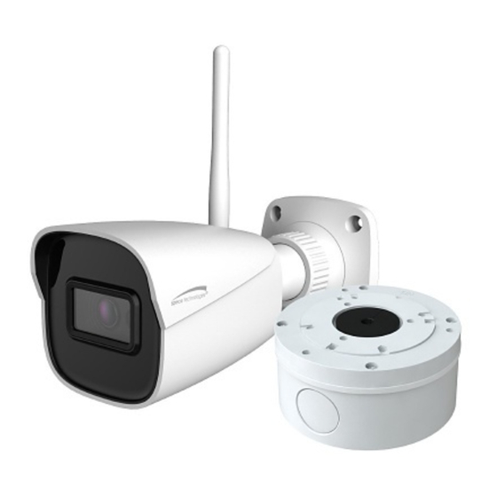
- Page 1 User Manual 4MP IP Camera O4VBW2 Please read this manual carefully before operating the unit and keep it for further reference...
- Page 2 Statement This guide is for reference only. Product, manuals, and specifications may be modified without prior notice. Speco Technologies reserves the right to modify these without notice and without incurring any obligation. Speco Technologies is not liable for any loss caused by improper operation.
- Page 3 Connect the equipment into an outlet on a circuit different from that to which the receiver is connected. Note: Before installation, check the package and make sure that all components are included. Contact your rep or Speco customer service department immediately if something is broken or missing in the package. Accessory name Amount...
-
Page 4: Table Of Contents
Table of Contents Introduction ..........................................2 Web Access and Login ......................................3 Live View..........................................5 Camera Configuration ......................................6 System Configuration ......................................6 4.1.1 System Information ....................................6 4.1.2 Date and Time ......................................6 4.1.3 Local Recording ....................................... 6 4.1.4 Storage ........................................ - Page 5 Video Search ........................................37 5.2.1 Local Video Search ....................................37 5.2.2 SD Card Video Search .................................... 38 Appendix ............................................41 Appendix 1 Troubleshooting ......................................41...
-
Page 6: Introduction
Thank you for purchasing this network camera! Please read this manual carefully before operating the unit and retain it for further reference. Should you require any technical assistance, please contact Speco Technologies Technical Support at 1-800-645-5516. Main Features Built-in PoE (Power over Ethernet) ... -
Page 7: Web Access And Login
② Install IP Scanner from the CD and run it after installation. IP Scanner is the tool for discovering the IP cameras on the local network. IP Scanner and Speco Blue Scanner can also be downloaded from www. specotech.com. ③ In the device list, the IP address, model number, and MAC address of each device will be listed. Select the applicable device and double click to open up the web viewer. - Page 8 If this is the first time for you to log in, the password prompt may only change the admin password. To change ONVIF password, you either have to check the “Match Onvif Password” box (if available) or go to the the ONVIF section to change the password. (ConfigNetworkPorts/ConnectionsOnvif)
-
Page 9: Live View
3 Live View The window below will be shown after logging in. The following table describes the icons on the live view interface Icon Description Icon Description Original size of resolution Zoom out (for motorized models) Fit (correct scale) Rule information display Auto (fill the window) SD card recording indicator Full screen (show video only) -
Page 10: Camera Configuration
4 Camera Configuration Press the “Setup” button to go to the configuration interface. Note: Wherever applicable, click the “Save” button to save the settings. 4.1 System Configuration 4.1.1 System Information In the “System Information” interface, the system information of the device is listed. 4.1.2 Date and Time To set the time and date, go to SystemDate and Time. -
Page 11: Storage
save to the local PC. Note: when you access your camera by the web browser without the plug-in, only Show Bitrate can be set in the above interface. 4.1.4 Storage Go to SystemStorage to go to the interface as shown below. ... - Page 12 Weekly schedule Set the alarm time from Monday to Sunday for a single week. Each day is divided in one-hour increments. Green means scheduled. Blank means unscheduled. “Add”: Add the schedule for a special day. Drag the mouse to set the time on the timeline. “Erase”: Delete the schedule.
-
Page 13: Image Configuration
same as the schedule recording (See Schedule Recording). 4.2 Image Configuration 4.2.1 Display Configuration In the display settings interface as shown below, various settings can be adjusted, such as brightness, contrast, hue, and saturation and so on. The common mode and day and night mode can be set up separately. The image effect can be quickly viewed by switching the configuration file. -
Page 14: Video / Audio Configuration
50Hz: reduces flicker in 50Hz lighting conditions. 60Hz: reduces flicker in 60Hz lighting conditions. Smart IR: Choose “ON” or “OFF”. This function can effectively avoid image overexposure so as to make the image more realistic. The higher the level is, the more overexposure compensation will be given. White Balance: Adjust the color temperature according to the environment automatically. - Page 15 Three video streams can be adjustable. Resolution: The size of image. Frame rate: The higher the frame rate, the video is smoother. Bitrate type: CBR and VBR are optional. Bitrate is related to image quality. CBR means that no matter how much change is seen in the video scene, the compression bitrate will be kept constant.
-
Page 16: Osd Configuration
4.2.3 OSD Configuration Go to VideoOSD interface as shown below. Set time stamp, device name, OSD content and picture overlap here. After enabling the corresponding display and entering the content, drag them to change their position. Then click the “Save” button to save the settings. 4.2.4 Video Mask Go to ImageVideo Mask interface as shown below. -
Page 17: Roi Configuration
Click the “Clear” button to delete the current video mask area. 4.2.5 ROI Configuration Go to ImageROI Config interface as shown below. An area in the image can be set as a region of interest. This area will have a higher bitrate than the rest of the image, resulting in better image quality for the identified area. -
Page 18: Exception Alarm
1. Check “Enable” check box to activate motion-based alarms. If unchecked, the camera will not send out any signals to trigger motion-based recording to the NVR or CMS, even if there is motion in the video. Alarm Holding Time: it refers to the time that the alarm extends for after an alarm ends. For instance, if the alarm holding time is set to 20 seconds, once the camera detects a motion, it will go to alarm and would not detect any other motion in 20 seconds. -
Page 19: Alarm Server
2. Click “Enable” and set the alarm holding time. 3. Set alarm trigger options. The setup steps are the same as motion detection. Please refer to motion detection chapter for details. SD Card Error When there are some errors in writing SD card, the corresponding alarms will be triggered. 1. -
Page 20: Event Configuration
4.4 Event Configuration This series of IP cameras supports certain smart functions, such as line crossing detection, region intrusion detection, etc. These events can be triggered as alarm events. For more accuracy, here are some recommendations for installation. Cameras should be installed on stable surfaces, as vibrations can affect the accuracy of detection. ... -
Page 21: Video Exception
Set the alarm area number and then enter the desired alarm area name. Only one alarm area can be added. Click the “Draw Area” button and then click around the area where you want to set as the alarm area in the image (the alarm area should be a closed area). Click the “Stop Draw”... -
Page 22: Line Crossing
1. Enable the applicable detection that is desired. Scene Change Detection: Alarms will be triggered if the scene of the video has changed. Video Blur Detection: Alarms will be triggered if the video becomes blurry. Abnormal Color Detection: Alarms will be triggered if the image is abnormal caused by color deviation. 2. - Page 23 targets cross the alarm line. Save Target Picture to SD Card: If it is enabled, the detected target cutout pictures will be captured and saved to the SD card when the targets cross the alarm line. Note: To save snapshots to the local PC, please enable “Local Smart Snapshot Storage” in the local config interface first. To save snapshots to the SD card, please install an SD card first.
-
Page 24: Region Intrusion
4.4.4 Region Intrusion Region Intrusion: Alarms will be triggered if the target intrudes into the defined areas. Go to EventRegion Intrusion interface as shown below. 1. Enable region intrusion detection and select the snapshot type and the detection target. Save Original Picture to SD Card: If it is enabled, the detected original pictures will be captured and saved to the SD card when the target intrudes into the pre-defined areas. -
Page 25: Network Configuration
Set the alarm area number on the right side. Up to 4 alarm areas can be added. Click the “Draw Area” button and then click around the area where you want to set as the alarm area in the image on the left side (the alarm area should be a closed area). -
Page 26: Wifi
Use IP address (take IPv4 for example)-obtain a local IP address automatically through DHCP. A typical router has a DHCP server built in, and therefore is able to assign an IP address to the camera. Use PPPoE-Click the “PPPoE Config” tab to go to the interface as shown below. Enable PPPoE and then enter the user name and password from your ISP. -
Page 27: Port
IP address of the camera in the address bar of the web browser to access the camera. Note:Use Speco Blue Scanner to locate the device IP address again as it may have changed after unplugging the cable. 4.5.3 Port... -
Page 28: Server Configuration
HTTP Port: The default HTTP port is 80. It can be changed to any port which is not occupied. HTTPS Port: The default HTTPs port is 443. It can be changed to any port which is not occupied. Data Port: The default data port is 9008. Please change it as necessary. RTSP Port: The default port is 554. -
Page 29: Ddns
Note: when adding the device to the third-party platform with ONVIF/RTSP protocol, please enter the username and password created in the above interface. 4.5.6 DDNS If the camera is set up with a DHCP connection, DDNS should be set for accessing the camera from the internet. 1. -
Page 30: 802.1X
2. Check the corresponding version checkbox (Enable SNMPv1, Enable SNMPv2, Enable SNMPv3) according to the version of the SNMP software that will be used. 3. Set the values for “Read SNMP Community”, “Write SNMP Community”, “Trap Address”, “Trap Port” and so on. Please make sure the settings are the same as that of the SNMP software. -
Page 31: Rtsp
authentication system to identify the device in a local network. If the camera connected to the network interface of the switch has passed the authentication of the switch, it can be accessed via the local network. Protocol type and EAPOL version: Please use the default settings. User name and password: The user name and password must be the same with the user name and password applied for and registered in the authentication server. -
Page 32: Ftp
Sender Address: sender’s e-mail address. User name and password: sender’s user name and password (you don’t have to enter the username and password if “Anonymous Login” is enabled). Server Address: The SMTP IP address or host name. Select the secure connection type at the “Secure Connection” pull-down list according to what’s required. SMTP Port: The SMTP port. -
Page 33: Https
Port: The port of the FTP server. Use Name and Password: The username and password that are used to login to the FTP server. 4.5.13 HTTPS HTTPs provides authentication of the web site and protects user privacy. Go to NetworkPorts/ConnectionsHTTPS as shown below. There is a certificate installed by default as shown above. -
Page 34: Qos
Click “Create” to create the certificate request. Then download the certificate request and submit it to the trusted certificate authority for signature. After receiving the signed certificate, import the certificate to the device. 4.5.14 QoS QoS (Quality of Service) function is used to provide different quality of services for different network applications. With the deficient bandwidth, the router or switch will sort the data streams and transfer them according to their priority to solve the network delay and network congestion by using this function. - Page 35 2. Enter user name in “User Name” textbox. 3. Enter letters or numbers in “Password” and “Confirm Password” textbox. Please set the password according to the requirement of the password security level (Go to SetupSecuritySecurity ManagementPassword Security interface to set the security level). 4.
-
Page 36: Online User
6. Click the “OK” button to save the settings. Note: To change the access level of a user, the user must be deleted and added again with the new access level. Delete user: 1. Select the user to be deleted in the user configuration list box. 2. -
Page 37: Maintenance Configuration
need to enter the username and password again to log in. Password Security Please set the password level and expiration time as needed. Password Level: Weak, Medium or Strong. Weak level: Numbers, special characters, upper or lower case letters can be used. You can choose one of them or any combination of them when setting the password. -
Page 38: Reboot
4.7.2 Reboot Go to MaintenanceReboot. Click the “Reboot” button to reboot the device. Timed Reboot Setting: If necessary, the camera can be set up to reboot on a time interval. Enable “Time Settings”, set the date and time and then click the “Save”... -
Page 39: Search
5 Search 5.1 Image Search In the Setup interface, click Search to go to the interface as shown below. Images that are saved on the PC or SD card can be found here. Note: When using the plug-in free browser, the local images cannot be searched. ... - Page 40 Click to return to the previous interface. SD Card Image Search 1. Choose “Picture”—“SD Card”. 2. Set time: Select date and choose the start and end time. 3. Choose the alarm events at the bottom of the interface. 4. Click to search the images.
-
Page 41: Video Search
Icon Description Icon Description Close: Select an image and click Close all: Click this button to close all this button to close the image. images. Save: Click this button to select the Save all: Click this button to select the path for saving the image on the path for saving all pictures on the PC. -
Page 42: Sd Card Video Search
Icon Description Icon Description Play button. After pausing the video, Pause button click this button to continue playing. Stop button Speed down Speed up Watermark display Enable / disable audio; drag the slider to adjust the volume after enabling audio. 5.2.2 SD Card Video Search Click Search to go to the interface as shown below. - Page 43 4. Select the alarm events at the bottom of the interface. 5. Select mix stream (video and audio stream) or video stream as needed. 6. Double click on a file name in the list to start playback. Note: cannot be displayed in the above interface via the plug-in free browser. Additionally, for plug-in free playback, playback mode switch (balanced/real-time/fluent mode) and downloading functions are not supported too.
- Page 44 Click “Set up” to set the storage directory of the video files. Click “Open” to play the video. Click “Clear List” to clear the downloading list. Click “Close” to close the downloading window.
-
Page 45: Appendix
Appendix Appendix 1 Troubleshooting IP Scanner does not show any device. Make sure that the PC that’s running IP Scanner is on the same local network as the devices. Internet Explorer cannot download ActiveX control. IE browser may be set up to block ActiveX. Follow the steps below. 1. - Page 46 Models: O4VBW2 Federal Communications Commission (FCC) Statements This device complies with Part 15 of the FCC Rules. Operation is subject to the following two conditions: (1) This device may not cause harmful interference, and (2) This device must accept any interference received, including interference that may cause undesired operation.
Need help?
Do you have a question about the O4VBW2 and is the answer not in the manual?
Questions and answers