ITT POWERLOCK BOX Translation Of The Original Operating Instructions
Hide thumbs
Also See for POWERLOCK BOX:
- Operation and maintenance manual (7 pages) ,
- Operating instructions manual (48 pages)
Table of Contents
Advertisement
Quick Links
POWERLOCK BOX
TRANSLATION OF THE ORIGINAL
OPERATING INSTRUCTIONS
CAS25124E
POWERLOCK BOX
Connection box to the connector system
Operating Instructions POWERLOCK BOX Rev. -
Page 1 of 40
EXPORT CODE C
COMMERCIAL. RESTRICTED TO EMBARGOED COUNTRIES AND DENIED PARTIES.
PRINTED COPIES ARE NOT MAINTAINED TO LATEST REVISION.
Advertisement
Chapters
Table of Contents

Related Manuals for ITT POWERLOCK BOX

Summary of Contents for ITT POWERLOCK BOX
- Page 1 OPERATING INSTRUCTIONS CAS25124E POWERLOCK BOX Connection box to the connector system Operating Instructions POWERLOCK BOX Rev. - Page 1 of 40 EXPORT CODE C COMMERCIAL. RESTRICTED TO EMBARGOED COUNTRIES AND DENIED PARTIES. PRINTED COPIES ARE NOT MAINTAINED TO LATEST REVISION.
-
Page 2: Imprint
All rights reserved INFORMATION! This publication is an integral part of the Technical Documen- tation for the “POWERLOCK BOX” and is protected by copy- right. Any use beyond the limits of copyright law without written per- mission is forbidden and subject to penalty. -
Page 3: Table Of Contents
Short description................... 10 Area of aplication ..................11 Overview and description ................12 Introduction of POWERLOCK System ............12 POWERLOCK BOX connection box ..............12 CONNECTOR POWERLOCK ................12 Color coding according to IEC 60445 ............13 Designs and versions ..................14 Housing versions .................... - Page 4 POWERLOCK BOX MICROSWITCH FOR REMOTE MONITORING ..........22 Transportation and storage ................23 Delivery of POWERLOCK BOX ............... 23 Scope of delivery POWERLOCK BOX ..............23 Transportation OF POWERLOCK BOX ............24 Installation/Commisioning ................25 Installation/Commisioning information ............25 Mounting in installation frame (Rack) ............26 Cutout installation frame ..................
-
Page 5: Declaration Of Conformity
POWERLOCK BOX DECLARATION OF CONFORMITY Operating Instructions POWERLOCK BOX Rev. - Page 5 of 40 EXPORT CODE C COMMERCIAL. RESTRICTED TO EMBARGOED COUNTRIES AND DENIED PARTIES. PRINTED COPIES ARE NOT MAINTAINED TO LATEST REVISION. - Page 6 POWERLOCK BOX Page 6 of 40 Operating Instructions POWERLOCK BOX Rev. - EXPORT CODE C COMMERCIAL. RESTRICTED TO EMBARGOED COUNTRIES AND DENIED PARTIES. PRINTED COPIES ARE NOT MAINTAINED TO LATEST REVISION.
-
Page 7: Information About The Document
This document is intended for the operator or persons authorized by the operator to perform tasks such as transportation, assembly (function), installation, opera- tion and maintenance of the POWERLOCK BOX and other tasks related to the POWERLOCK BOX. It additionally contains information and instructions regarding the disposal of packaging, transportation material, and possibly accumulating problematic sub- stances (e.g. -
Page 8: Description Of The Terms
POWERLOCK BOX DESCRIPTION OF THE TERMS In the designation of the POWERLOCK BOX technical terms or abbreviations of technical terms can be found which are listed and described here. Contact type PD Power Drain: Connector equipped with a "female" contact in a "male"... -
Page 9: Fig. 2: Powerlock Box With Lid (A) And Without Lid (B)
POWERLOCK BOX Lid: Lid of the POWERLOCK BOX provided with a seal. The lid can be locked with a 6 mm square key. Both the variants of the POWERLOCK BOX with lid and the variants without lid comply with protection class IP 65. -
Page 10: Intended Use
INTENDED USE SHORT DESCRIPTION The POWERLOCK BOX connection box described here is a connection unit in 19" format with 5 inputs for the power supply of a three-phase network for high-cur- rent connections with up to 660 A current intensity. The POWERLOCK BOX con- nection box is designed for the use of POWERLOCK type connectors. -
Page 11: Area Of Aplication
POWERLOCK BOX AREA OF APLICATION The POWERLOCK BOX connection box has been designed and manufactured us- ing state-of-the-art techniques and in accordance with approved safety regula- tions and the recognized standards EN 61984, 60512, 60664-1 and 60529. Never- theless, when not used as intended, risks for the user or third parties may still arise or the high power charging system and other material assets may be dam- aged. -
Page 12: Overview And Description
INTRODUCTION OF POWERLOCK SYSTEM POWERLOCK BOX CONNECTION BOX The POWERLOCK BOX is a connection unit in 19" format with 5 inputs for the power supply of a three-phase network. It guarantees sequential plugging and unplugging of connectors in correct order (PE, N, L1, L2, L3). The POWERLOCK BOX is designed for the use of the POWERLOCK type connectors. -
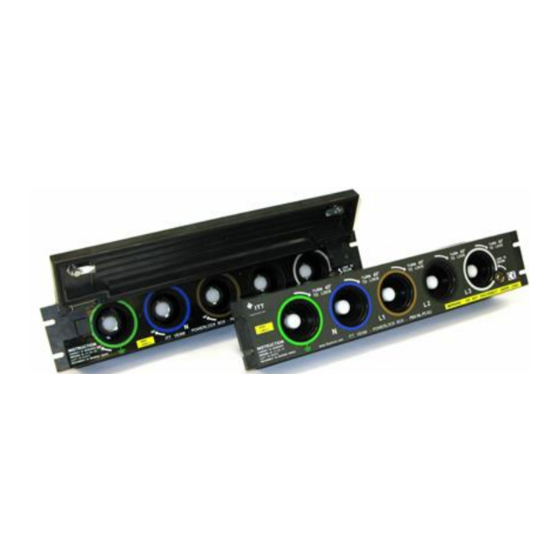
Page 13: Color Coding According To Iec 60445
POWERLOCK BOX COLOR CODING ACCORDING TO IEC 60445 Fig. 4: POWERLOCK BOX with POWERLOCK connectors (EU coding) Ground Neutral Line 1 Line 2 Line 3 (L1) (L2) (L3) Australia GREEN BLUE BLACK WHITE Europe GREEN GREY BLACK BLUE BROWN North America... -
Page 14: Designs And Versions
Up to 400 A rated current: PBX-xx-xx-xx-400 Up to 660 A rated current: PBX-xx-xx-xx-660 Page 14 of 40 Operating Instructions POWERLOCK BOX Rev. - EXPORT CODE C COMMERCIAL. RESTRICTED TO EMBARGOED COUNTRIES AND DENIED PARTIES. PRINTED COPIES ARE NOT MAINTAINED TO LATEST REVISION. -
Page 15: Fig. 5: Ordering Information For The Powerlock Box
POWERLOCK BOX Fig. 5: Ordering information for the POWERLOCK BOX Fig. 6: PBX-NL-PS-EU-660, without cover, without flange, EU coding, 660 A Operating Instructions POWERLOCK BOX Rev. - Page 15 of 40 EXPORT CODE C COMMERCIAL. RESTRICTED TO EMBARGOED COUNTRIES AND DENIED PARTIES. -
Page 16: Fig. 7: Pbx-Sl-Pd-Eu-400, With Cover, Without Flange, Eu Coding, 400 A
POWERLOCK BOX Fig. 7: PBX-SL-PD-EU-400, with cover, without flange, EU coding, 400 A Fig. 8: POWERLOCK BOX with cover and flange Page 16 of 40 Operating Instructions POWERLOCK BOX Rev. - EXPORT CODE C COMMERCIAL. RESTRICTED TO EMBARGOED COUNTRIES AND DENIED PARTIES. -
Page 17: Technical Specifications
Threaded bolt M12 Weight with cover 3,75 kg Weight without cover 3,25 kg Operating Instructions POWERLOCK BOX Rev. - Page 17 of 40 EXPORT CODE C COMMERCIAL. RESTRICTED TO EMBARGOED COUNTRIES AND DENIED PARTIES. PRINTED COPIES ARE NOT MAINTAINED TO LATEST REVISION. -
Page 18: Electrical
IP65 Protection class, plugged UL94-V0 Flammability RoHS Directive (Hazardous Consistent Substances) Page 18 of 40 Operating Instructions POWERLOCK BOX Rev. - EXPORT CODE C COMMERCIAL. RESTRICTED TO EMBARGOED COUNTRIES AND DENIED PARTIES. PRINTED COPIES ARE NOT MAINTAINED TO LATEST REVISION. -
Page 19: Dimensions And Measurements
DIMENSIONS AND MEASUREMENTS POWERLOCK BOX WITH FLANGE Fig. 9: PBX SLF (with cover, with flange), bottom PBX NLF (without cover, with flange) Operating Instructions POWERLOCK BOX Rev. - Page 19 of 40 EXPORT CODE C COMMERCIAL. RESTRICTED TO EMBARGOED COUNTRIES AND DENIED PARTIES. -
Page 20: Powerlock Box Without Flange
Fig. 10: PBX SL (with cover, without flange), bottom PBX NL (without cover, without flange) Page 20 of 40 Operating Instructions POWERLOCK BOX Rev. - EXPORT CODE C COMMERCIAL. RESTRICTED TO EMBARGOED COUNTRIES AND DENIED PARTIES. PRINTED COPIES ARE NOT MAINTAINED TO LATEST REVISION. -
Page 21: Label And Marking
POWERLOCK BOX LABEL AND MARKING INFORMATION! The label or marking of the POWERLOCK BOX are placed on the front (connector POWERLOCK) and on the cover. The labeling differs depending on regional regulations (color coding according to IEC 60445) and the different rated currents (400 A and 660 A). -
Page 22: Microswitch For Remote Monitoring
POWERLOCK BOX MICROSWITCH FOR REMOTE MONITORING For remote monitoring, the POWERLOCK BOX is equipped with a three-pin con- nector (ITT CANNON Trident Connector) on the back of the housing. The three- pin connector is connected to a microswitch inside the POWERLOCK BOX. -
Page 23: Transportation And Storage
(if possible). Immediately report any missing parts and/or damage to the delivery as a result of poor packaging or due to transportation to the manufacturer or distributor. Operating Instructions POWERLOCK BOX Rev. - Page 23 of 40 EXPORT CODE C COMMERCIAL. -
Page 24: Transportation Of Powerlock Box
POWERLOCK BOX TRANSPORTATION OF POWERLOCK BOX INFORMATION! Only store the POWERLOCK BOX in dry, enclosed rooms while observing the pictograms on the packaging. The type of packaging may vary depending on the component, weight and selected shipping route. Page 24 of 40 Operating Instructions POWERLOCK BOX Rev. -
Page 25: Installation/Commisioning
“POWERLOCK” connector system, ensure that the af- fected areas (also areas supplied by external sources) are de- energized and secured against accidental switch-on! Modifications (of any kind) of the POWERLOCK BOX and POWERLOCK type connectors are strictly forbidden! Operating Instructions POWERLOCK BOX Rev. -... -
Page 26: Mounting In Installation Frame (Rack)
Optionally, the installation can also be made in existing devices with adaptations. The POWERLOCK BOX is always mounted in a horizontal position so that the con- nectors are separated to avoid friction of the cables. During the assembly of the heavy POWERLOCK BOX, the instructed personnel must wear PPE. -
Page 27: Cutout Installation Frame
ERLOCK BOX. Versions with horizontal flange (NLF or SLF) com- pletely enclose the mounting frame. Fig. 14: Dimensions for cutout Operating Instructions POWERLOCK BOX Rev. - Page 27 of 40 EXPORT CODE C COMMERCIAL. RESTRICTED TO EMBARGOED COUNTRIES AND DENIED PARTIES. -
Page 28: Electrical Connection (Current Conductor)
For a rated current of 660 A, at least a conductor cross- section of 240 mm² must be used. Fig. 15: Rear side of housing POWERLOCK BOX Page 28 of 40 Operating Instructions POWERLOCK BOX Rev. - EXPORT CODE C COMMERCIAL. -
Page 29: Connection For Remote Monitoring
Cavity A and C connect the micro switch in the "closed" state (normally closed, Normally Closed NC). Cavity D is not used Fig. 16: Components of the Trident Connector Operating Instructions POWERLOCK BOX Rev. - Page 29 of 40 EXPORT CODE C COMMERCIAL. RESTRICTED TO EMBARGOED COUNTRIES AND DENIED PARTIES. - Page 30 POWERLOCK BOX To assemble the Trident Connector to the POWERLOCK BOX, proceed as follows: Figure Action Cut the insulation of the cable ends to a length of 6 mm. Tin-plating of contacts and cable ends. Solder cable and contact.
- Page 31 Screw the end housing onto the con- nector housing, hand-tight. Attach suitable clamps. Tighten screws. Operating Instructions POWERLOCK BOX Rev. - Page 31 of 40 EXPORT CODE C COMMERCIAL. RESTRICTED TO EMBARGOED COUNTRIES AND DENIED PARTIES. PRINTED COPIES ARE NOT MAINTAINED TO LATEST REVISION.
-
Page 32: Connection Connector Powerlock
Before connecting the POWERLOCK connectors, make sure that the rated current of the cables and connectors used cor- responds to that of the POWERLOCK BOX and the power con- ductors. Only genuine ITT Powerlock connectors may be used with this junction box. -
Page 33: Exemplary Connection (Eu-Coding)
EXEMPLARY CONNECTION (EU-CODING) Insert the E (green) ground connector into the corresponding connector on the POWERLOCK BOX. The “PUSH” arrow on the connector label is at the “12 o'clock” position. Insert the connector and push it in as far as it will go. Internal spring-loaded locking pins now release a rotational movement. -
Page 34: Fig. 18: Insert The Connector And Push It In As Far As It Will Go
Fig. 18: Insert the connector and push it in as far as it will go Fig. 19: Turn the plug connector clockwise approx. 45° until it stops Page 34 of 40 Operating Instructions POWERLOCK BOX Rev. - EXPORT CODE C COMMERCIAL. RESTRICTED TO EMBARGOED COUNTRIES AND DENIED PARTIES. -
Page 35: Fig. 20: Lock The Connection With A 6 Mm Square Key
POWERLOCK BOX Fig. 20: Lock the connection with a 6 mm square key Fig. 21: All connectors are coupled and interlocked Operating Instructions POWERLOCK BOX Rev. - Page 35 of 40 EXPORT CODE C COMMERCIAL. RESTRICTED TO EMBARGOED COUNTRIES AND DENIED PARTIES. -
Page 36: Disconnecting The Connections
CONTROL OF THE COMPONENTS At regular intervals (at least once a year), a visual inspection of all components of the POWERLOCK BOX for damage and an assessment of their functionality must be carried out. The visual inspection must include the following components: ... -
Page 37: Cleaning Of The Components
The usage of so-called “aggressive” cleaning agents (highly al- kaline or acidic) must be checked. No cleaning with water or steam jet cleaner. The POWERLOCK BOX must not be im- mersed in liquids. DISPOSAL OF THE POWERLOCK BOX... -
Page 38: List Of Figures
LIST OF FIGURES Fig. 1: Connecting Uses ..................... 8 Fig. 2: POWERLOCK BOX with lid (A) and without lid (B) .......... 9 Fig. 3: POWERLOCK BOX with flange (A) and without flange (B) ......9 Fig. 4: POWERLOCK BOX with POWERLOCK connectors (EU coding) ..... 13 Fig. -
Page 39: Remarks And Notes
………………………………………………………………………………………………………………………………………………………………. ………………………………………………………………………………………………………………………………………………………………. ………………………………………………………………………………………………………………………………………………………………. ………………………………………………………………………………………………………………………………………………………………. ………………………………………………………………………………………………………………………………………………………………. ………………………………………………………………………………………………………………………………………………………………. ………………………………………………………………………………………………………………………………………………………………. ………………………………………………………………………………………………………………………………………………………………. ………………………………………………………………………………………………………………………………………………………………. ………………………………………………………………………………………………………………………………………………………………. ………………………………………………………………………………………………………………………………………………………………. Operating Instructions POWERLOCK BOX Rev. - Page 39 of 40 EXPORT CODE C COMMERCIAL. RESTRICTED TO EMBARGOED COUNTRIES AND DENIED PARTIES. PRINTED COPIES ARE NOT MAINTAINED TO LATEST REVISION. -
Page 40: Operating Instructions Powerlock Box Rev
D-71384 Weinstadt www.ittcannon.com 2021 © ITT Cannon GmbH All rights reserved Page 40 of 40 Operating Instructions POWERLOCK BOX Rev. - EXPORT CODE C COMMERCIAL. RESTRICTED TO EMBARGOED COUNTRIES AND DENIED PARTIES. PRINTED COPIES ARE NOT MAINTAINED TO LATEST REVISION.
Need help?
Do you have a question about the POWERLOCK BOX and is the answer not in the manual?
Questions and answers