Advertisement
Quick Links
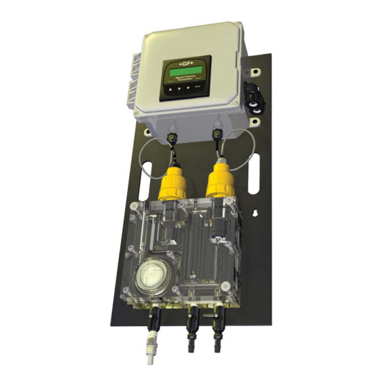
Signet 4630 Chlorine Analyzer System
*3-4630.090*
3-4630.090 Rev A 09/10 English
CAUTION!
1.
Follow instructions carefully to avoid personal injury.
2.
Do not exceed the maximum pressure or temperature specifi cations.
3.
Mounting the Chlorine System in an outdoor box, in areas with elevated temperatures, may
cause damage to the system if the enclosure's internal temperature exceeds the temperature
specifi cation of the Chlorine Analyzer.
4.
Do not alter product construction.
5.
For use with clean fresh water only.
6.
Disconnect AC power before opening wiring enclosure.
7.
This panel system uses AC voltages. Wiring should be done by qualifi ed personnel only.
1.
Description
2.
Dimensions
3.
Component Identifi cation
4.
Mounting
5.
Tubing Connections
1. Description
The Signet Chlorine Analyzer System is an integrated, all-in-one chlorine panel system designed to measure free chlorine in
drinking water and clean fresh water treatment applications.
Features:
•
Complete chlorine analyzer system allows quick setup and easy
installation. Connect to a water source and plug it in.
•
Unique integrated clear fl ow cell combines sensors, fl ow regulator,
fi lter and rotameter in one compact unit.
•
Built-in rotameter facilitates fl ow rate confi rmation at a glance.
•
Integrated fl ow regulator with removable fi lter accepts inlet pressures
of 15 to 150 psi while maintaining constant fl ow and minimal pressure
to the sensors.
•
Water fl ows vertically into sensor tip, eliminating bubble entrapment.
Raised exit in fl ow cell sensor chamber ensures sensors stay
submerged even when system and fl ow is turned off.
•
System is supplied with pre-wired electronics, power cable, 4 to 20 mA
current loop and relay output capability.
•
Flow cell accommodates two sensors; one chlorine and an optional
pH sensor.
•
Automatic pH and temperature compensation or manual pH value
input capability for chlorine reading accuracy.
•
Easy viewing of the transmitter via the bright backlit LCD display.
•
Moisture proof NEMA 4X wiring enclosure.
•
Exterior panel enclosure available for outdoor mounting applications.
Refer to the individual component manuals for detailed component
information.
•
8630-3 Chlorine Transmitter Manual
•
2630-2 Amperometric Chlorine Electrode Manual
•
2650 Amperometric Electronics Manual
•
2724 pH/ORP Electrode Manual
•
2750-7 pH Electronics Manual
p.1
6.
p.2
7.
Wiring
p.3
8.
Water Flow
p.4
9.
Flow Cell Components
p.4
10.
Cleaning
p.5
11.
p.7
12.
Flow Cell Assembly
p.8
13.
p.9
14.
p.10
15.
English
p.11
p.12
p.13
p.14
p.16
Advertisement

Subscribe to Our Youtube Channel
Related Manuals for GF Signet 4630


Summary of Contents for GF Signet 4630
- Page 1 Signet 4630 Chlorine Analyzer System English *3-4630.090* 3-4630.090 Rev A 09/10 English CAUTION! Follow instructions carefully to avoid personal injury. Do not exceed the maximum pressure or temperature specifi cations. Mounting the Chlorine System in an outdoor box, in areas with elevated temperatures, may cause damage to the system if the enclosure's internal temperature exceeds the temperature specifi...
- Page 2 2. Dimensions 165 mm 305 mm (12 in.) (6.5 in.) 254 mm (10 in.) 25 mm (1.0 in.) Ø 7 mm (0.27 in.) Ø 13 mm (0.52 in.) 79.3 mm (3.12 in.) 4630 Chlorine Analyzer System...
- Page 3 3. Component Identifi cation Wiring enclosure Transmitter Output conduits Power cable conduit Vent pH Sensor Chlorine sensor with electronics with electronics Plug Flow range limits Flow cell block Flow rate indicator Flow cell O-rings Flow regulator with strainer Hex bolt Knurled thumb nut Sampling port Inlet port...
- Page 4 4. Mounting • Mount the panel according to electrical, building, and or plumbing codes and seismic requirements. • The panel must be mounted vertically in an upright position. • Use four 6 mm (¼ in.) diameter screws or bolts of suffi cient length to mount the panel to a sturdy vertical surface.
-
Page 5: System Setup P.5 11. O-Rings
6. System Setup Overview Follow the steps below to set up a new Chlorine Analyzer System. Refer to the individual component manuals for detailed information. Step 1. Mount the panel on a vertical fl at surface using appropriate hardware. Step 2. Install the infl uent water source to the "Inlet Port" nipple assembly of the fl ow cell. Use tubing that is properly rated for the system pressure and secure with hose clamps. - Page 6 7. Wiring WARNING This panel system is wired for AC voltages that can injure or kill. Wiring should be done by qualifi ed personnel only. Disconnect AC power before opening wiring enclosure. Follow all local and government recommendations and methods for installation of electrical connections to and between the system and other devices.
- Page 7 Wiring - continued WARNING This panel system is wired for AC voltages that can injure or kill. Wiring should be done by qualifi ed personnel only. Disconnect AC power before opening wiring enclosure. 12 to 24 VDC Input Wiring Conversion 100 to 240 VAC input •...
- Page 8 8. Water Flow Flow Rate The fl ow rate is in the proper range when the center line on the fl oat is within the Min. and Max. markers on the fl ow cell. The fl ow range limits are 30.24 to 45.36 L/h (8 to 12 gal/h). Sensor Removal Caution Over time, a sensor can get tight in the fl...
- Page 9 9. Flow Cell Components Flow cell nut (1700-2501) Flat washer (3200-2578) Flow cell back block (3-4630.150) Spacer ring Stainless steel fi lter (3-4630.391) Pressure regulator Pressure regulator outer O-ring (large) Pressure regulator outer O-ring (small) (3-4630.390) Flow cell O-rings (4 segments) Flow cell front block (3-4630.150) Flat washer...
- Page 10 10. Cleaning Under certain conditions, a dirty fl ow cell and fi lter can create a chlorine demand which could lower the chlorine concentration in the water fl owing past the chlorine sensor. Because of this, it is recommended to clean the fi lter and fl ow cell on a regular basis. The frequency of necessary cleaning will depend on the application in which the system is being used and the level of accuracy required.
- Page 11 11. O-rings • The sealing of the fl ow cell is accomplished by four cut O-ring segments and two round O-rings sealing the fl ow regulator. Refer to the illustration below for special O-ring fi tting instructions. Butt all O-ring joints together so there is no gap.
- Page 12 12. Flow Cell Assembly WARNING! Do not over tighten fl ow cell bolts. Maximum torque is 8.1 Nm (72 Lb-In). Over tightening the bolts can damage the fl ow cell. Do not over tighten the bolts in an attempt to stop a leak. Install the assembled pressure Install the nut and washers.
-
Page 13: 13. Troubleshooting
13. Troubleshooting The troubleshooting table below outlines possible causes and remedies related to the fl ow cell panel system. Refer to the transmitter and sensor manuals for specifi c component troubleshooting. Problem Possible Cause Remedies No water fl ow • Inlet pressure below 1 bar (15 psi) •... -
Page 14: Ordering
14. Ordering Information Mfr. Part No. Code Description 3-4630-20 159 001 691 Chlorine panel, transmitter, free chlorine sensor (0 to 5 ppm) with electronics, no pH sensor 3-4630-21 159 001 692 Chlorine panel, transmitter, free chlorine sensor (0 to 5 ppm) with sensor electronics, pH sensor with electronics 3-2630-2 159 001 662... - Page 15 Notes 4630 Chlorine Analyzer System...
-
Page 16: Specifi Cations
15. Specifi cations Signet 4630 Chlorine Analyzer System General Environmental Requirements Compatible Sensors: Storage Temperature: Signet 3-2630-2 Free Chlorine Sensor 0 °C to 65 °C (32 °F to 149 °F) Signet 3-2724-00 Flat pH Electrode Operating Temperature: Materials: 0 °C to 45 °C (32 °F to 113 °F)
Need help?
Do you have a question about the Signet 4630 and is the answer not in the manual?
Questions and answers