
Subscribe to Our Youtube Channel
Related Manuals for Clarke SBR305


Summary of Contents for Clarke SBR305
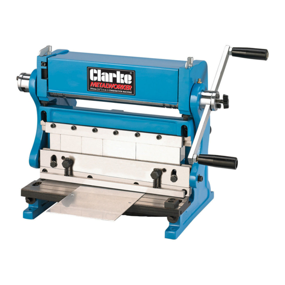
- Page 1 3 IN1 SHEET METAL MACHINE MODEL NO: SBR305 PART NO: 6560000 OPERATION & MAINTENANCE INSTRUCTIONS LS0620 - ISS 3...
- Page 2 INTRODUCTION Thank you for purchasing this CLARKE 3 in1 Sheet Metal Machine. Before attempting to use this product, please read this manual thoroughly and follow the instructions carefully. In doing so you will ensure the safety of yourself and that of others around you, and you can look forward to your purchase giving you long and satisfactory service.
-
Page 3: Safety Instructions For Machinery
SAFETY INSTRUCTIONS FOR MACHINERY 1. READ THE ENTIRE MANUAL BEFORE USE. Machinery presents serious injury hazards to untrained users. 2. ALWAYS USE APPROVED SAFETY GLASSES WHEN OPERATING MACHINERY. Everyday eyeglasses are NOT safety glasses. 3. ALWAYS USE HEARING PROTECTION WHEN OPERATING MACHINERY. Machinery noise can cause permanent hearing loss. - Page 4 ADDITIONAL SAFETY INSTRUCTIONS FOR 3-IN-1 SHEET METAL MACHINES 1. OVERLOADING. Attempting to overload this machine beyond the capacities specified in the “Specifications” on page 35 could cause personal injury or property damage. DO NOT extend the hand crank to apply additional force. 2.
-
Page 5: Warning Labels
WARNING: LIKE ALL MACHINERY THERE IS POTENTIAL DANGER WHEN OPERATING THIS MACHINE. ACCIDENTS ARE FREQUENTLY CAUSED BY LACK OF FAMILIARITY OR FAILURE TO PAY ATTENTION. USE THIS MACHINE WITH RESPECT AND CAUTION TO DECREASE THE RISK OF OPERATOR INJURY. IF NORMAL SAFETY PRECAUTIONS ARE OVERLOOKED OR IGNORED, SERIOUS PERSONAL INJURY MAY OCCUR.- CAUTION: NO LIST OF SAFETY GUIDELINES CAN BE COMPLETE. -
Page 6: Parts Identification
PARTS IDENTIFICATION Fig. 1 Parts & Service: 020 8988 7400 / E-mail: Parts@clarkeinternational.com or Service@clarkeinternational.com... - Page 7 Remove the packaging materials from around your machine and make sure that you have the following items. If you discover the machine is damaged in any way, please contact your Clarke dealer. A. Sheet Metal Machine B. Shear & Brake Rear Work Stop C.
-
Page 8: Site Considerations
SITE CONSIDERATIONS FLOOR LOAD Refer to the Specifications for the weight and footprint specifications of your machine. Some workbenches or stands may require additional reinforcement to support the machine, workpiece, and the forces applied during operation. PLACEMENT LOCATION Consider existing and anticipated needs, size of material to be processed through each machine, and space for auxiliary stands, work... - Page 9 ASSEMBLY In addition to the assembly procedures below, some disassembly is required to remove storage grease and re-lubricate the cleaned parts. TO ASSEMBLE YOUR MACHINE: 1. Remove one of the cap screws on the hand crank hub, rotate the end cap out of the way, then insert the hand crank into the slot (see Figure 7).
- Page 10 CLEANING THE MACHINE FINGERS: 1. Loosen the two hex bolts securing the finger receiver/upper shear blade to the frame (see Figure 10). Fig. 10 2. Move the table back until the upper shear blade can pass down behind the table blade by loosening the two cap screws securing the shear table to the frame and rotating the table...
- Page 11 7. Place a thin piece of wood on the finger receiver, as shown in Figure 13, then reinstall the fingers so that they rest on the wood. Make sure the tops of the fingers are between the gib and the casting. NOTE: Install the widest finger to the right, then repeat with each smaller finger.
- Page 12 OPERATING - SLIP ROLLERS CAUTION: THE ROLLERS OF THIS MACHINE PRESENT A PINCHING HAZARD. MAKE SURE NO BODY PART OR CLOTHING IS NEAR THE ROLLERS DURING OPERATION. FAILURE TO FOLLOW THIS WARNING MAY RESULT IN FINGERS, HAIR, OR CLOTHING BEING PULLED INTO THE MACHINE, CAUSING PERSONAL INJURY.
- Page 13 CREATING CURVES Your sheet metal machine can easily create constant radius curves in sheet metal up to 1 mm in thickness. The method of creating a specific radius is a trial and error process. Due to the many variations among metal workpieces, no single configuration of the rollers will reproduce the same curve in all materials.
-
Page 14: Creating Cylinders
NOTE: If your workpiece has an undesired initial flat, as illustrated in Figure 19, you can remove it by flipping the workpiece around and pass it through the front of the machine so that the initial flat enters last. 4. Slightly tighten the diameter Fig. - Page 15 You can use the slip roll to create a Fig. 20 bend with the correct radius so that the two ends meet, forming a 150 mm diameter cylinder (Figure 20). NOTE: Performing multiple passes through the machine with gradual reductions in the curve radius produces better results than trying to make the curve in one or two...
- Page 16 5. Turn the hand crank to process the material through the slip Fig. 23 rollers. Continue turning until the workpiece is completely through the upper and lower rollers, as illustrated in Figure 23. 6. Rotate the workpiece 180°, insert the curved end into the rollers, Fig.
- Page 17 REMOVING THE WORKPIECE FROM T H E R OLLERS TO REMOVE THE WORKPIECE FROM THE TOP ROLLER: 1. Insert the supplied hexagon key into the retainer pin and rotate the retainer pin until the flat portion of the pin is facing toward the roller or to the right, as shown in Figure 26.
-
Page 18: Bending Wire
BENDING WIRE Your sheet metal machine can bend wires, rods, and small-diameter tubing between the diameters of ” ” (see Figure 28). To ensure even pressure on the material, place the workpiece in the smallest possible groove on either side of the rollers. Although a ”... -
Page 19: Operating - Brake
OPERATING - BRAKE BRAKE OVERVIEW Fig. 29 The brake of the SBR305 is used to make bends of 0°-90° in sheet metal up to 1 mm in thickness and 305 mm in width. When you use the hand crank, the brake fingers force the... - Page 20 BENDING SHEET METAL Tip: To reduce the chance of scoring your workpiece when using the brake, always keep the fingers and receivers clean and lubricated (refer to Steps 8- 13 beginning on page 10 for detailed instructions), and free of burrs or other blemishes.
- Page 21 Remove the fingers you do not need. OPERATING - SHEARING SHEARING OVERVIEW The SBR305 has a set of reversible blades that shear mild steel up to 1 mm in thickness and 305 mm in width. When you use the hand crank...
-
Page 22: Material Thickness
MATERIAL THICKNESS The SBR305 is designed to bend and shear mild steel sheet metal up to 1 mm in thickness (mild steel). Parts & Service: 020 8988 7400 / E-mail: Parts@clarkeinternational.com or Service@clarkeinternational.com... -
Page 23: Maintenance
SEMI-ANNUAL MAINTENANCE: • Lubricate the roller bushings. CLEANING & PROTECTING Cleaning the SBR305 is relatively easy. Use a cloth and degreasing spirits to wipe down the machine. LUBRICATION Keep your SBR305 properly lubricated to help ensure long life and smooth operation of the machine. - Page 24 GEARS Clean away grease and built-up grime from the top and bottom roller gear teeth, as shown in Figure 38, with a stiff brush and degreasing spirits. When dry, apply a small amount of grease to the teeth, then use the Fig.
- Page 25 However, if you are not comfortable performing the sharpening procedure or do not have access to a professional sharpening service, replacement blades are available through the Clarke spares department TO REVERSE OR REPLACE THE SHEARING BLADES: 1. Remove the hex bolts and springs that secure the shear holddown bar (see Figure 42).
- Page 26 • If both cutting edges are worn or nicked, either properly sharpen the cutting face or replace the blade. 4. Re-install the holddown bar, then check that the shearing blade gap adjustment is correct as instructed in “Shearing Blade Gap Adjustment” below.
- Page 27 ADJUSTING THE SHEAR TABLE 1. Loosen the cap screws on either end of the shear table that secure it to the machine (see Figure 45). 2. Evenly rotate the table adjustment screws to adjust the position of the shearing table until the blade gap is even, then re- tighten the cap screws to secure the table in place.
- Page 28 BRAKE ALIGNMENT WARNING: THE BRAKE FINGERS ON THIS MACHINE PRESENTS A PINCHING HAZARD. MAKE SURE NO BODY PART OR CLOTHING IS NEAR THE AREA WHERE METAL BENDING OCCURS. FAILURE TO FOLLOW THIS WARNING MAY RESULT IN SEVERE PERSONAL INJURY. During the life of your machine, you may need to align the brake fingers with the finger receiver from side-to-side.
-
Page 29: Troubleshooting
TROUBLESHOOTING Slip Roll Operation PROBLEM CAUSE SOLUTION Slip roll creates Top and rear rollers not Use the diameter adjustment knobs cones when trying parallel. to make the rollers parallel. to make a cylinder. Creases or Excessive pressure applied Reduce the radius and perform the wrinkles in the when rolling. - Page 30 Properly adjust blade gap for or tearing. material. Loose blades. Remove blades, clean thoroughly, and re-install. If this does not solve your problem, please contact the Clarke service department. Parts & Service: 020 8988 7400 / E-mail: Parts@clarkeinternational.com or Service@clarkeinternational.com...
-
Page 31: Exploded Diagram - Parts List
EXPLODED DIAGRAM - PARTS LIST Parts & Service: 020 8988 7400 / E-mail: Parts@clarkeinternational.com or Service@clarkeinternational.com... - Page 32 Left Frame TGSBR30501 Driving Roller TGSBR30531 Table TGSBR30502 Driven Roller TGSBR30532 Upper Support TGSBR30503 Protecting Cover TGSBR30533 Beam Pin M6x10 TGSBR30534 Pivot Arm TGSBR30504 Eccentric Shaft TGSBR30535 Right Frame TGSBR30505 TGSBR30536 Lower Support Bar TGSBR30506 Jacket TGSBR30537 Eccentric Cap TGSBR30507 Flat Key 6x 20mm TGSBR30538 Guide Stud...
-
Page 33: Specifications
SPECIFICATIONS Part Number 6560000 Weight. 43 kg Width/Depth/Height 550 x 390 x 390 mm Capacities: Maximum Workpiece Width 305 mm Maximum Workpiece Thickness 1 mm Pan/Box Brake Minimum Reverse Bend 9 mm Pan/Box Brake Maximum Side Height @ 90° 42 mm Slip Roll Minimum Cylinder Diameter 39 mm Slip Roll Wire Sizes (L to R) -
Page 34: Declaration Of Conformity
DECLARATION OF CONFORMITY Parts & Service: 020 8988 7400 / E-mail: Parts@clarkeinternational.com or Service@clarkeinternational.com... - Page 35 NOTES Parts & Service: 020 8988 7400 / E-mail: Parts@clarkeinternational.com or Service@clarkeinternational.com...
Need help?
Do you have a question about the SBR305 and is the answer not in the manual?
Questions and answers