
Subscribe to Our Youtube Channel
Related Manuals for Clarke SBR760


Summary of Contents for Clarke SBR760
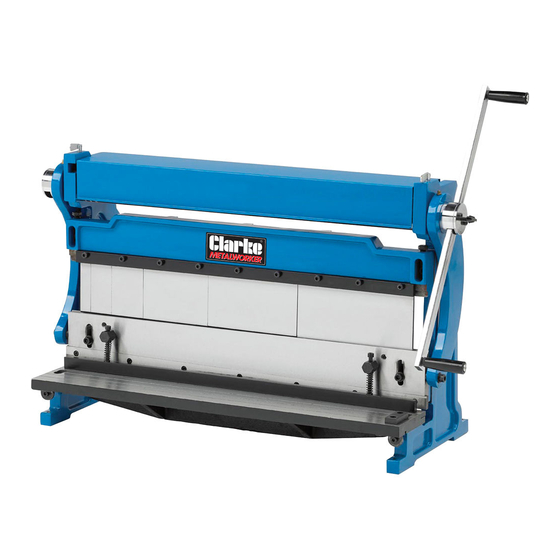
- Page 1 3 IN1 SHEET METAL MACHINE MODEL NO: SBR760 PART NO: 6560030 OPERATION & MAINTENANCE INSTRUCTIONS LS0618 ISS 2...
- Page 2 INTRODUCTION Thank you for purchasing this CLARKE 3 in1 Sheet Metal Machine. Before attempting to use this product, please read this manual thoroughly and follow the instructions carefully. In doing so you will ensure the safety of yourself and that of others around you, and you can look forward to your purchase giving you long and satisfactory service.
-
Page 3: Safety Instructions For Machinery
SAFETY INSTRUCTIONS FOR MACHINERY 1. READ THE ENTIRE MANUAL BEFORE USE. Machinery presents serious injury hazards to untrained users. 2. ALWAYS USE APPROVED SAFETY GLASSES WHEN OPERATING MACHINERY. Everyday eyeglasses are NOT safety glasses. 3. ALWAYS USE HEARING PROTECTION WHEN OPERATING MACHINERY. Machinery noise can cause permanent hearing loss. - Page 4 ADDITIONAL SAFETY INSTRUCTIONS FOR 3-IN-1 SHEET METAL MACHINES 1. OVERLOADING. Attempting to overload this machine beyond the capacities specified in the “Specifications” on page 35 could cause personal injury or property damage. DO NOT extend the hand crank to apply additional force. 2.
-
Page 5: Warning Labels
WARNING: LIKE ALL MACHINERY THERE IS POTENTIAL DANGER WHEN OPERATING THIS MACHINE. ACCIDENTS ARE FREQUENTLY CAUSED BY LACK OF FAMILIARITY OR FAILURE TO PAY ATTENTION. USE THIS MACHINE WITH RESPECT AND CAUTION TO DECREASE THE RISK OF OPERATOR INJURY. IF NORMAL SAFETY PRECAUTIONS ARE OVERLOOKED OR IGNORED, SERIOUS PERSONAL INJURY MAY OCCUR.- CAUTION: NO LIST OF SAFETY GUIDELINES CAN BE COMPLETE. -
Page 6: Parts Identification
PARTS IDENTIFICATION Fig. 1 Parts & Service: 020 8988 7400 / E-mail: Parts@clarkeinternational.com or Service@clarkeinternational.com... - Page 7 Remove the packaging materials from around your machine and make sure that you have the following items. If you discover the machine is damaged in any way, please contact your Clarke dealer. A. Sheet Metal Machine B. Shear & Brake Rear Work Stop C.
-
Page 8: Site Considerations
SITE CONSIDERATIONS FLOOR LOAD Refer to the Specifications for the weight and footprint specifications of your machine. Some workbenches or stands may require additional reinforcement to support the machine, workpiece, and the forces applied during operation. PLACEMENT LOCATION Consider existing and anticipated needs, size of material to be processed through each machine, and space for auxiliary stands, work... - Page 9 ASSEMBLY In addition to the assembly procedures below, some disassembly is required to remove storage grease and re-lubricate the cleaned parts. TO ASSEMBLE YOUR MACHINE: 1. Remove the end cap screws from the end cap. 2. Rotate the lock knob out until it is flush with the rear of the end cap.
- Page 10 OPERATING - SLIP ROLLERS CAUTION: THE ROLLERS OF THIS MACHINE PRESENT A PINCHING HAZARD. MAKE SURE NO BODY PART OR CLOTHING IS NEAR THE ROLLERS DURING OPERATION. FAILURE TO FOLLOW THIS WARNING MAY RESULT IN FINGERS, HAIR, OR CLOTHING BEING PULLED INTO THE MACHINE, CAUSING PERSONAL INJURY.
- Page 11 CREATING CURVES Your sheet metal machine can easily create constant radius curves in sheet metal up to 1 mm in thickness (mild steel). The method of creating a specific radius is a trial and error process. Due to the many variations among metal workpieces, no single configuration of the rollers will reproduce the same curve in all materials.
-
Page 12: Creating Cylinders
NOTE: If your workpiece has an undesired initial flat, as illustrated in Figure 14, you can remove it by flipping the workpiece around and pass it through the front of the machine so that the initial flat enters last. 4. Slightly tighten the diameter Fig. - Page 13 You can use the slip roll to create a Fig. 15 bend with the correct radius so that the two ends meet, forming a 150 mm diameter cylinder (Figure 15). NOTE: Performing multiple passes through the machine with gradual reductions in the curve radius produces better results than trying to make the curve in one or two...
- Page 14 5. Turn the hand crank to process the material through the slip Fig. 18 rollers. Continue turning until the workpiece is completely through the upper and lower rollers, as illustrated in Figure 18. 6. Rotate the workpiece 180°, insert the curved end into the rollers, Fig.
-
Page 15: Bending Wire
REMOVING THE WORKPIECE FROM T H E R OLLERS TO REMOVE THE WORKPIECE FROM THE TOP ROLLER: 1. Rotate the thickness leaf bolts anticlockwise until they no longer apply pressure to the top roller. CAUTION: THE SHARP EDGES OF SHEET METAL CAN QUICKLY CUT YOUR HANDS. -
Page 16: Operating - Brake
OPERATING - BRAKE BRAKE OVERVIEW Fig. 24 The brake of the SBR760 is used to make bends of 0°-90° in sheet metal up to 1 mm in thickness and 760 mm in width. When you use the hand crank, the brake fingers force the... - Page 17 BENDING SHEET METAL Tip: To reduce the chance of scoring your workpiece when using the brake, always keep the fingers and receivers clean and lubricated (refer to page 21 for detailed instructions), and free of burrs or other blemishes. Also, apply a strip of sturdy tape along the top and bottom of the bend line.
- Page 18 OPERATING - SHEARING SHEARING OVERVIEW The SBR760 has a set of reversible blades that shear mild steel up to 1 mm in thickness and 760 mm in width. When you use the hand crank to...
-
Page 19: Material Thickness
MATERIAL THICKNESS The SBR760 is designed to bend and shear mild steel sheet metal up to 1 mm in thickness. Parts & Service: 020 8988 7400 / E-mail: Parts@clarkeinternational.com or Service@clarkeinternational.com... -
Page 20: Maintenance
• Lubricate the gears and hand crank bushings. SEMI-ANNUAL MAINTENANCE: • Lubricate the roller bushings. CLEANING Cleaning the SBR760 is relatively easy. Use cloth and degreasing spirits to wipe down the machine. LUBRICATION Keep your SBR760 properly lubricated to help ensure long life and smooth operation of the machine. - Page 21 CLEAN THE MACHINE FINGERS 1. Loosen the two hex bolts securing Fig. 33 the finger receiver/upper shear blade to the frame (see Figure 33). 2. Move the table back until the upper shear blade can pass down behind the table blade by loosening the two cap screws securing the shear table to the frame and rotating the table...
- Page 22 7. Place a thin piece of wood on the finger receiver, as shown in Figure 36, then reinstall the fingers so that they rest on the wood. Make sure the tops of the fingers are between the gib and the casting. NOTE: Install the widest finger to the right, then repeat with each smaller finger.
- Page 23 ROLLER BUSHINGS 1. Remove the top roller from the machine, then remove the bushings from the ends of the roller (see Figure 40). 2. Use a shop rag and degreasing spirits to clean the bushings and the ends of the roller, Fig.
-
Page 24: Tools Needed
The upper shearing blade uses a 5° relief edge and the lower table blade does not. However, if you are not comfortable performing the sharpening procedure or do not have access to a professional sharpening service, replacement blades are available through the Clarke spares department. Tools Needed Tools Needed... - Page 25 hole to keep the blade in place as you remove the rest of the cap screws. 3. Inspect the blade cutting edge that was in use, for wear, nicks, or burrs. • If the cutting edge shows wear or nicks and the other cutting edge has not been used, rotate the blade and re-install it.
- Page 26 ADJUSTING THE SHEAR TABLE. Tools Needed Hex Wrench 6mm Standard Screwdriver #2 TO ADJUST THE BLADE GAP BY MOVING THE TABLE: 1. Loosen the cap screws on either end of the shear table that secure it to the machine (see Figure 44). 2.
- Page 27 TO ADJUST THE BLADE GAP WITH THE BLADE BOW: 1. Hold the adjustment bolt still, then turn the jam nut to adjust the center of the cross beam in or out (see Figure 48). • If the shear test cut was clean on the ends of the shear table but not in the middle, turn the jam nut counterclockwise to force the adjustment bolt against the cross beam, moving it in toward the front.
- Page 28 3. Place a piece of heavy flat bar stock or a heavy metal ruler across the finger receiver, as shown in Figure 46. 4. Lower the brake fingers until one just rests on the metal bar, as shown in Figure 46. 5.
-
Page 29: Troubleshooting
TROUBLESHOOTING Slip Roll Operation PROBLEM CAUSE SOLUTION Slip roll creates Top and rear rollers not Use the diameter adjustment knobs cones when trying parallel. to make the rollers parallel. to make a cylinder. Creases or Excessive pressure applied Reduce the radius and perform the wrinkles in the when rolling. - Page 30 Properly adjust blade gap for or tearing. material. Loose blades. Remove blades, clean thoroughly, and re-install. If this does not solve your problem, please contact the clarke service depart- ment. Parts & Service: 020 8988 7400 / E-mail: Parts@clarkeinternational.com or Service@clarkeinternational.com...
-
Page 31: Specifications
SPECIFICATIONS Part Number 6560030 Weight. 126 kg Width/Depth/Height 905 x 390 x 565 mm Capacities: Maximum Workpiece Width 760 mm Maximum Workpiece Thickness 1 mm Pan/Box Brake Minimum Reverse Bend 9 mm Pan/Box Brake Maximum Side Height @ 90° 105 mm Slip Roll Minimum Cylinder Diameter 39 mm Slip Roll Wire Sizes (L to R) -
Page 32: Exploded Diagram - Parts List
EXPLODED DIAGRAM - PARTS LIST Parts & Service: 020 8988 7400 / E-mail: Parts@clarkeinternational.com or Service@clarkeinternational.com... - Page 33 LEFT WALL TGSBR76001 GEAR TGSBR76030 WORK BENCH TGSBR76002 LOWER ROLL TGSBR76031 CROSSBEAM TGSBR76003 UPPER ROLL TGSBR76032 CRANK ARM TGSBR76004 PROTECTING COVER TGSBR76033 RIGHT WALL TGSBR76005 PIN (3X18) TGSBR76034 REAR FRAME TGSBR76006 ECCENTRIC TGSBR76035 MOUNTING COVER TGSBR76007 HANDLE PRESS PLATE BRACKET TGSBR76008 ROLLER ADJUSTMENT SPRING...
-
Page 34: Declaration Of Conformity
DECLARATION OF CONFORMITY Parts & Service: 020 8988 7400 / E-mail: Parts@clarkeinternational.com or Service@clarkeinternational.com... - Page 35 NOTES Parts & Service: 020 8988 7400 / E-mail: Parts@clarkeinternational.com or Service@clarkeinternational.com...
Need help?
Do you have a question about the SBR760 and is the answer not in the manual?
Questions and answers