Advertisement
Quick Links
Hardware Installation Guide
Industrial Ethernet Switch
IES-C1160
IES-C1160-1P
1. Introduction
IES-C1160 series Ethernet Switch are designed with a very compact housing size and
are fitted with a robust housing. To ensure reliable, error-free operation, and to prevent
damage or injury, please read the operating instructions, all safety information provided
in this document and any other safety information that were supplied with the product.
2. Safety notice
Switch off the electrical power before removing the power connection!
Éteignez le courant avant de le débrancher!
The device heats up during operation. Allow the unit to cool down or use
protection gloves when carrying out any work.
L'équipement se réchauffe pendant le fonctionnement. Laissez l'appareil
refroidir ou utilisez des gants de protection lorsque vous effectuez des
travaux.
The device may only be connected to the supply voltage shown on the
product label. Higher voltage than specified will destroy the device.
L'appareil ne peut être connecté qu'à la tension d'alimentation indiquée
sur l'étiquette du produit. Une tension supérieure à celle spécifiée peut
endommager l'appareil.
The device must be supplied by a class 2 source.
L'équipement doit être fourni par une source d'alimentation de classe 2.
Installation, commissioning and maintenance may only be performed by
qualified electricians.
Seuls les électriciens qualifiés peuvent effectuer l'installation, la mise en
service et la maintenance.
Observe the operating instructions.
Suivez les instructions de fonctionnement.
Indoor use and pollution degree 2, it must be wiped with a dry cloth for
clean up the device and label.
L'utilisation intérieure et la contamination sont de classe 2I et doivent
être essuyées avec un chiffon sec pour nettoyer l'équipement et les
étiquettes.
Shall be mounted in the Industrial Control Panel and ambient
temperature is not exceed 60 degrees C.
Doit être installé dans le panneau de commande industriel, la
température ambiante ne dépasse pas 60 ℃
Intended use
The device is intended for the realization of communication networks within an industrial
environment, The device may only be used within the scope of the specified technical
data. The device is intended to be mounted to a well-grounded mounting surface, such
as a metal panel. Any other use may result in unintentional malfunction and damage.
Observing the documentation is part of the intended use.
Environmental conditions
This equipment is intended to be used in a restricted access location.
When planning the installation site make sure that the ambient temperature during
operation will not exceed the temperature given in the technical data.
Also make sure that the air flow will not be compromised by other devices.
Ensure that the mounted and wired device is not exposed to any mechanical stress
1
3. Package Checklist
Your Ethernet Switch is shipped with the following items:
Ethernet Switch
Hardware Installation Guide (printed)
2/6-Pin Terminal connector
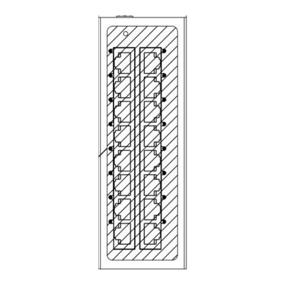
4. Panel Layouts
1
1. Grounding screw / Frame ground
2
Note: The shielding ground of the LAN port is
3
electrically connected to the grounding screw.
4
2.Terminal block for power input PWR
1
3. Power input LED
4.16 x 10/100Base –TX Port
5
5. LAN Port Link/Activity LED
5. DIP Switch
DIP Switch
IES-C1160-1P
Setting
Description
DIP Switch
Enable the Quality of Service to handle
packet priorities in four WRR queues.
QoS priority mapping matrix in each queue
ON
Quality of Service
QoS3bit
priority
(QoS)
Queues
WRR
OFF
Disable the Quality of service
Enables broadcast storm protection (only
Broadcast storm
ON
allow maximum of 2000 broadcast packets per
protection
second)for each Ethernet port.
(BSP)
OFF
Disables the broadcast storm protection
.
IES-C1160
7,6
5,4
3,2
1,0
3
2
1
0
8
4
2
1
2
6. Mounting Dimensions
(units=mm)
7. DIN-Rail Mounting
The Switch support horizontal and vertical installation.The DIN rail kit can be adjusted
according to the actual application to meet different installation requirements.
Horizontal Installation
Installation
Step 1: Select the mounting position for the
device and guarantee adequate space and heat
dissipation. Clip the upper part of the rail holder
to the DIN rail, push the upper part of the device
down slightly in the direction of arrow 1.
Step 2: push the front of the module toward the
mounting surface until it audibly snaps into place
in the direction of arrow 2.
Uninstallation
Step 1: As shown in the following figure, press
the device downward in the direction of arrow 1
until the bottom of the device is detached from
the DIN rail.
Step 2: Rotate the device in the direction of
arrow 2 until the device is removed from the DIN
rail.
3
Vertical installation
Advertisement

Related Manuals for ORiNG IES-C1160


Summary of Contents for ORiNG IES-C1160
- Page 1 4.16 x 10/100Base –TX Port 5. LAN Port Link/Activity LED IES-C1160 series Ethernet Switch are designed with a very compact housing size and are fitted with a robust housing. To ensure reliable, error-free operation, and to prevent damage or injury, please read the operating instructions, all safety information provided in this document and any other safety information that were supplied with the product.
- Page 2 IES-C1160:One removable 6-pin terminal block The switch power supply inputs which are located on the 2/6-pin terminal block. Refer to 10/100Base-T(X) RJ45 Pinouts Overload Current illustration below for correct wiring. IES-C1160 supply redundant power ,user can MDI Port Pinouts MDI-X Port Pinouts 8-pin RJ45...
Need help?
Do you have a question about the IES-C1160 and is the answer not in the manual?
Questions and answers