Advertisement
Quick Links
SWITCH
I N D U S T R I A L
Q
I
uick
nstallation
Introduction
IES-3160
is managed Redundant Ring Ethernet switch with 16x10/100Base-
T(X) ports. With completely support of Ethernet Redundancy protocol, O-
Ring (recovery time < 10ms over 250 units of connection), O-Chain,
MRP
*NOTE
and MSTP/RSTP/STP (IEEE 802.1s/w/D) can protect your
mission-critical applications from network interruptions or temporary
malfunctions with its fast recovery technology. O-Chain is the revolutionary
network redundancy technology that provides the add-on network
redundancy topology for any backbone network, O-Chain allows multiple
redundant network rings of different redundancy protocols to join and
function together as a larger and more robust compound network topology.
O-Chain providing ease-of-use while maximizing fault-recovery swiftness,
flexibility, compatibility, and cost-effectiveness in one set of network
redundancy topology. All function of
IES-3160
and convenient by a powerful windows utility — Open-Vision. In addition, the
wide operating temperature range from -40 to 75 C can satisfy most of
operating environment. Therefore, the switch is one of the most reliable
choice for highly-managed Ethernet application.
The product is open type, intended to be installed in and industrial control panel or an
enclosure.
*NOTE : This function is available by request only.
Package Contents
The device is shipped with the following items. If any of these items is missing
or damaged, please contact your customer service representative for
assistance.
Contents
Pictures
Number
IES-3160
CD
QIG
Wall-mount Kit
Console Cable
DIN-rail Kit
Preparation
Before you begin installing the device, make sure you have all of the package
contents available and a PC with Microsoft Internet Explorer 6.0 or later, for
using web-based system management tools.
Safety & Warnings
Elevated Operating Ambient: If installed in a closed environment, make sure
the operating ambient temperature is compatible with the maximum
ambient temperature (Tma) specified by the manufacturer.
Q I G
IES-3160
G
uide
Reduced Air Flow: Make sure the amount of air flow required for safe operation of the
equipment is not compromised during installation.
Mechanical Loading: Make sure the mounting of the equipment is not in a hazardous
condition due to uneven mechanical loading
Circuit Overloading: Consideration should be given to the connection of the equipment to
the supply circuit and the effect that overloading of the circuits might have on overcurrent
protection and supply wiring. Appropriate consideration of equipment nameplate ratings
should be used when addressing this concern.
Dimension
can be managed centralized
o
74.3
P15
P16
PWR
PWR1
P13
P14
PWR2
P11
P12
P9
P10
P7
P8
P5
P6
P3
P3
P4
P1
P1
P2
IES-3160
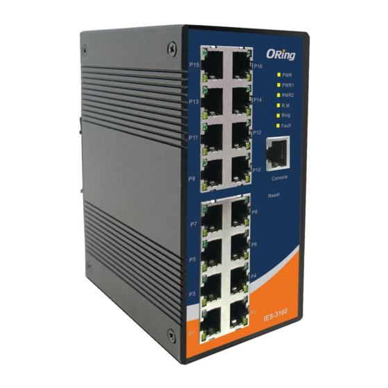
Panel Layouts
X 1
Front View
8
P15
P16
X 1
9
10
P13
P14
P11
P12
X 1
P9
P10
P7
P8
X 2
P5
P6
P3
P3
P4
P1
P1
P2
IES-3160
X 1
Rear View
X 1
1907-200-XX
IES-3160
Unit =mm (Tolerance ±0.5mm)
66.0
40.0
18.0
107.5
1. Power LED
2. PWR1 LED
1
PWR
PWR1
2
3. PWR2 LED
3
PWR2
4
4. R.M. status LED
5
6
5. Ring status LED
6. Faulty relay indicator
7
7. Console port
8. Link/Act LED for Ethernet port
11
9. Full/Half-duplex indicator
10. LAN ports
11. Reset button
Bottom View
1
1. Din-rail screw holes
PWR-2
Fault
PWR-1
2. Wall-mount screw holes
1A@24V
2
V2- V2+
V1- V1+
DC12-48V
2
1
1. Terminal block
2. Grounding screw
2
PRINTED ON RECYCLED PAPER
Industrial Managed Ethernet Switch
Installation
DIN-rail Installation
Step 1: Slant the device and screw the Din-rail kit onto the back of the device, right in the
middle of the back panel.
Step 2: Slide the device onto a DIN-rail from the Din-rail kit and make sure the device clicks
into the rail firmly.
Wall-mounting
Step 1: Screw the two pieces of wall-mount kits onto both ends of the rear panel of the
device. A total of six screws are required, as shown below.
Step 2: Use the device, with wall mount plates attached, as a guide to mark the
correct locations of the wall-mounting screws.
74.3
Step 3: Insert a screw head through the large part of the keyhole-shaped aperture on the
plate, and then slide the device downwards. Tighten the screw for added stability.
Network Connection
The switch provides standard Ethernet ports. According to the link type, the switch uses CAT
3,4,5,5e UTP cables to connect to any other network devices (PCs, servers, switches,
routers, or hubs). Please refer to the following table for cable specifications.
Cable Types and Specifications:
Cable
Type
10BASE-T
Cat. 3, 4, 5 100-ohm
100BASE-TX
Cat. 5 100-ohm UTP
Version 2.1
P15
P16
PWR
PWR1
PWR2
P13
P14
P11
P12
P9
P10
P7
P8
P5
P6
P3
P3
P4
P1
P1
P2
IES-3160
Max. Length
Connector
UTP 100 m (328 ft)
RJ-45
UTP 100 m (328 ft)
RJ-45
Quick Installation Guide
Advertisement

Related Manuals for ORiNG IES-3160


Summary of Contents for ORiNG IES-3160
- Page 1 Version 2.1 SWITCH IES-3160 Industrial Managed Ethernet Switch I N D U S T R I A L uick nstallation uide Introduction Installation DIN-rail Installation IES-3160 is managed Redundant Ring Ethernet switch with 16x10/100Base- Reduced Air Flow: Make sure the amount of air flow required for safe operation of the equipment is not compromised during installation.
- Page 2 Operating Humidity 5% to 95% Non-condensing 1A@24V PWR2 and the RELAY are located on the terminal block. using ORing’s Open-Vision management utility, Operating Alttitude Up to 2000m STEP 1: Insert the negative/positive wires into the V-/V+ terminals, please go to ORing website.
Need help?
Do you have a question about the IES-3160 and is the answer not in the manual?
Questions and answers
is it convert FO to RJ45 ? How many ports belongs to FO and ports qty and How many ports belongs to RJ45? and qty
The ORiNG IES-3162GC (not IES-3160) has fiber optical ports with SFP connectors and supports both multi-mode and single-mode with LC connectors. It also includes RJ-45 Ethernet ports. However, the exact number of fiber optic (FO) and RJ-45 ports is not specified in the provided information.
This answer is automatically generated