Advertisement
Quick Links
SWITCH
I N D U S T R I A L
Q
I
uick
nstallation
Introduction
IES-2050A
is a lite-managed Ethernet switch. With very compact size of
housing, you can install
IES-2050A
easily. In addition, it also supports of
Ethernet Redundancy protocol, O-Ring (recovery time < 10ms over 250 units
of connection), O-Chain and STP/RSTP (IEEE802.1w/D) can protect your
mission-critical applications from network interruptions or temporary
malfunctions with its fast recovery technology.
setting ability of Web-GUI and Windows Utility, also support the simple DIP-
Switch setting function which offer great flexibility to set up the Ring. IES-
2050A is with rigid IP-30 housing design and can operate under harsh
environment. The feature of wide operating temperature ranges from -40 C
to 75 C can satisfy most requirement of operation.
o
•O-Ring: O-Ring is ORing's proprietary redundant ring technology, with
recovery time of less 10 milliseconds and up to 250 nodes. The O-Ring
redundant ring technology can protect mission-critical application from
network interruptions or temporary malfunction with its fast recover
technology.
•O-Chain: O-Chain is the revolutionary network redundancy technology that
provides the add-on network redundancy topology for any backbone
network, O-Chain allows multiple redundant network rings of different
redundancy protocols to join and function together as a larger and more
robust compound network topology. O-Chain providing ease-of-use while
maximizing fault-recovery swiftness, flexibility, compatibility, and cost-
effectiveness in one set of network redundancy topology.
The product is open type, intended to be installed in and industrial control panel or an
enclosure.
Package Contents
The device is shipped with the following items. If any of these items is
missing or damaged, please contact your customer service representative for
assistance.
Contents
Pictures
Number
IES-2050A
CD
DIN-rail Kit
Wall-mount Kit
QIG
Preparation
Before you begin installing the device, make sure you have all of the package
contents available and a PC with Microsoft Internet Explorer 6.0 or later, for
using web-based system management tools.
Safety & Warnings
Elevated Operating Ambient: If installed in a closed environment, make sure
the operating ambient temperature is compatible with the maximum
ambient temperature (Tma) specified by the manufacturer.
Reduced Air Flow: Make sure the amount of air flow required for safe operation
of the equipment is not compromised during installation.
Q I G
IES-2050A
G
uide
Mechanical Loading: Make sure the mounting of the equipment is not in a hazardous
condition due to uneven mechanical loading.
Circuit Overloading: Consideration should be given to the connection of the equipment to the
supply circuit and the effect that overloading of the circuits might have on overcurrent protection
and supply wiring. Appropriate consideration of equipment nameplate ratings should be used
when addressing this concern.
IES-2050A
provides the
Dimension Unit =mm (Tolerance ±0.5mm)
o
IES-2050A
P1
Ring R.M.
P2
5
4
3
2
1
26.1
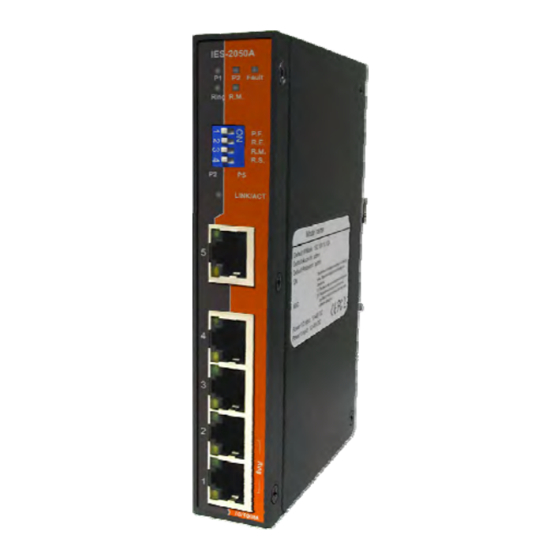
Panel Layouts
Front View
3
IES-2050A
1
P1
P2 Fault
2
Ring R.M.
X 1
P.F.
R.E.
6
R.M.
R.S.
P2
P5
X 1
5
7
8
4
9
X 1
3
2
1
X 2
10/100M
Rear View
X 1
1907-200-E2050AXXX2-FX022
IES-2050A
94.9
24.3
13.1
25.6
Ø3.0
Ø5.9
8.5
P2 Fault
P.F.
25.0
R.E.
R.M.
R.S.
P5
14.0
6.05
10/100M
Top View
1
2
1. Power 1 LED
4
PWR-2
1A@24V
PWR-1
5
2. R.M status LED
3. Power 2 LED
V2+ V2-
V1+ V1-
4. Fault indicator
1
5. Ring status LED
6. DIP switch
1. Wall-mount screw holes
7. LNK/ACT LED for LAN ports
2. Terminal block
8. LAN port
3. Reset button
9. Duplex/Collision LED for LAN ports
4. Ground wire
1. Din-rail screw holes
1
PRINTED ON RECYCLED PAPER
Industrial Lite-Managed Switch
Installation
Use the mounting kits attached with the package and follow the steps below to install the
switch to a rail or to the wall.
DIN-rail Installation
Step 1: Slant the switch and screw the Din-rail kit onto the back of the switch, right in the
middle of the back panel.
Step 2: Slide the switch onto a DIN-rail from the Din-rail kit and make sure the switch clicks
into the rail firmly.
Wall-mounting
Step 1: Screw the wall-mount kit (in the package) onto the back of the switch. A total
of eight screws are required, as shown below.
Step 2: Use the switch, with wall mount plates attached, as a guide to mark the
correct locations of the wall-mounting screws.
3
Step 3: Insert a screw head through the large part of the keyhole-shaped aperture on
DC12-48V
the plate, and then slide the switch downwards. Tighten the screw for added
stability.
Reset
4
Instead of screwing the screws in all the way, it is advised to leave a space of
about 2mm to allow room for sliding the switch between the wall and the
screws.
Network Connection
The series have standard Ethernet ports. Depending on the link type, the switch uses CAT
3, 4, 5, 5e UTP cables to connect to network devices (PCs, servers, switches, routers, or
hubs). Please refer to the following table for cable specifications.
Version 2.2
IES-2050A
P1
P2 Fault
Ring R.M.
P.F.
R.E.
R.M.
R.S.
P2
P5
5
4
3
2
1
10/100M
Quick Installation Guide
Advertisement

Related Manuals for ORiNG IES-2050A


Summary of Contents for ORiNG IES-2050A
- Page 1 The feature of wide operating temperature ranges from -40 C 13.1 to 75 C can satisfy most requirement of operation. •O-Ring: O-Ring is ORing's proprietary redundant ring technology, with recovery time of less 10 milliseconds and up to 250 nodes. The O-Ring 25.6...
- Page 2 IEC/EN 61000-4-4 (EFT Power 2KV, Signal 1KV), IEC/EN 61000-4-5 (Surge: Power 0.5KV), IEC/EN 61000-4-6 (CS: 10V), IEC/EN 61000-4-8(PFMF), IEC/EN 61000-4-11 (DIP)) using ORing’s Open-Vision management utility, and power input 2. Follow the steps below to wire redundant please go to ORing website.
Need help?
Do you have a question about the IES-2050A and is the answer not in the manual?
Questions and answers