
Subscribe to Our Youtube Channel
Related Manuals for Sungrow SG125HV-30


Summary of Contents for Sungrow SG125HV-30
- Page 1 User Manual SG125HV-30 PV Grid-connected Inverter SG125HV-30-UEN-Ver11-202003 Version: 1.1...
- Page 3 About This Manual Validity This manual is for the SG125HV-30, a three-phase PV grid-connected transformerless inverter, (hereinafter referred to as inverter unless otherwise specified). The inverter is grid-connected, transformer-less, robust and of high conversion efficiency. The SG125HV-30 is custom-made for the optical storage DC-coupled integrated system and is not sold as a stand-alone product.
- Page 4 Symbols Explanation Important instructions contained in this manual should be followed during installation, operation and maintenance of the inverter. They will be highlighted by the following symbols. DANGER indicates a hazard with a high level of risk which, if not avoided, will result in death or serious injury.
- Page 5 Symbols on the Inverter Body WARNING: ELECTRIC SHOCK HAZARD. THE DC CONDUCTORS OF THIS PHOTOVOLTAIC SYSTEM ARE UNGROUNDED AND MAY BE ENERGIZED. WARNING: Electric Shock Hazard. The DC conductors of this photovoltaic system are normally ungrounded but will become intermittently grounded without indication when the inverter measures the PV array isolation.
- Page 6 WARNING: ELECTRIC SHOCK HAZARD. THE DC CONDUCTORS OF THIS PHOTOVOLTAIC SYSTEM ARE UNGROUNDED AND MAY BE ENERGIZED. WARNING: Electric Shock Hazard. The DC conductors of this photovoltaic system are normally ungrounded but will become intermittently grounded without indication when the inverter measures the PV array isolation. CAUTION: Risk of Electric Shock,Do Not Remove Cover.
-
Page 7: Table Of Contents
Contents About This Manual ..............I Safety Instructions ............. 1 Product Description ............7 Intended Usage ................. 7 Product Introduction ..............8 2.2.1 Model Description ..............8 2.2.2 Appearance ................9 2.2.3 Dimensions ................10 2.2.4 LED Indicator Panel ..............10 2.2.5 DC Switch ................ - Page 8 Terminal Description ..............32 6.1.1 Appearance ................32 6.1.2 Dimensions of Terminal ............34 AC Side Cable Connection ............35 6.2.1 AC side requirements .............. 35 6.2.2 Grid Connection ..............38 6.2.3 Requirements for OT/DT Terminal (AC) ........39 6.2.4 Connecting the Inverter to Grid ..........40 Connecting Inverter to PV Arrays ..........
- Page 9 9.2.2 Maintenance Instruction ............70 10 iSolarCloud APP ............... 72 10.1 Brief Introduction ..............72 10.2 Download and Install ............... 72 10.3 Sync setup instructions ............73 10.4 Menu ..................73 10.5 Login ..................74 10.5.1 Requirements ................ 74 10.5.2 Login Steps ................74 10.6 Home page ................
-
Page 11: Safety Instructions
The unit is thoroughly tested and strictly inspected before delivery. Damage may still occur during shipping. If there is visible damage to the packing case or the inner contents, or if there is something missing, contact SUNGROW or the forwarding company. - Page 12 1 Safety Instructions User Manual There is a risk of injury due to improperly handling the device! Always follow the instructions in the manual when moving and positioning the inverter. Injuries, serious wounds, or bruises may occur if the device is improperly handled.
- Page 13 Operate the inverter by strictly following the descriptions in this manual to avoid unnecessary personal injury and property damage. Arc flash, fire or explosion may occur if done otherwise and SUNGROW will hold no liability for damages. The following improper operations can cause an arc flash, fire and explosion inside the device.
- Page 14 Do not replace the inverter internal components without permission. Damage to the inverter may occur and it may void any or all warranty rights from SUNGROW. There is a risk of inverter damage due to electrostatic discharge!
- Page 15 User Manual 1 Safety Instructions printed circuit boards contain components sensitive electrostatic discharge. Wear a grounding wrist band when handling the boards. Avoid unnecessary touching of the boards. Others Certain parameter settings (country selection, etc.) by the iSolarCloud APP must only be done by qualified persons.
- Page 16 1 Safety Instructions User Manual b) When the photovoltaic array is exposed to light, it supplies a DC voltage to this equipment. CAUTION: Risk of electric shock from energy stored in the capacitor. Do not remove cover until 5 minutes after disconnecting all sources of supply. CAUTION: Hot surfaces –...
-
Page 17: Product Description
1 Product Description 1.1 Intended Usage SG125HV-30; a transformerless three-phase PV grid-connected inverter, is an integral component in the PV power system. The inverter is designed to convert the direct current power generated from the PV modules into grid-compatible AC current and feeds the AC current to the utility grid. -
Page 18: Product Introduction
1 Product Description User Manual Transformer L1 L2 L3 Inverter If the Anti-PID function is to be enabled ensure that: The inverter is applied in the IT system. The downstream transformer meets the requirements described in 5.2.1 Medium-voltage Transformers. ... -
Page 19: Appearance
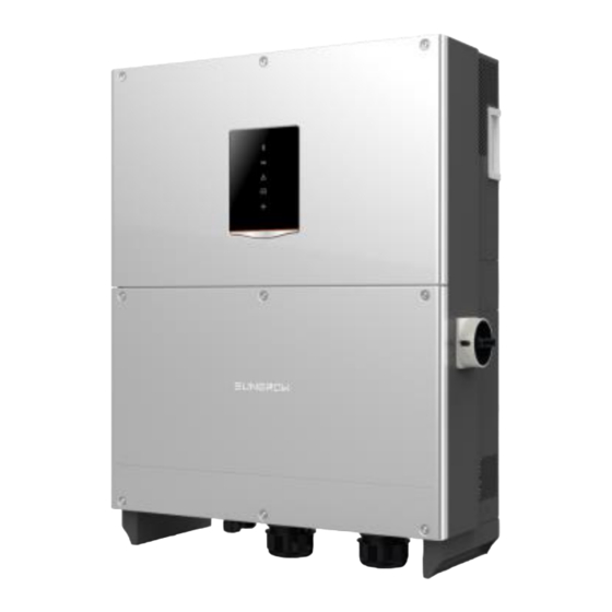
User Manual 1 Product Description Tab. 1-1 Version difference 1.2.2 Appearance Fig. 1-2 Appearance * Pictures are indicative only. Product in kind prevail. Name Description HMI interface to indicate the present working LED indicator panel state of the inverter. Protective components to safely disconnect DC DC switch side current. -
Page 20: Dimensions
1 Product Description User Manual 1.2.3 Dimensions 296mm 670mm(26.4inch) (11.7inch) Fig. 1-3 Dimensions of the inverter 1.2.4 LED Indicator Panel As an HMI, the LED indicator panel on the inverter front panel indicates the present working state of the inverter. Fig. -
Page 21: Dc Switch
User Manual 1 Product Description LED indicator LED color LED state Definition connected, the communication channel has no data interaction No device connected to the inverter through the Bluetooth. The Bluetooth communication is Periodical connected and there is data flash communication The RS485 communication cable connected... -
Page 22: Ac Switch
RS485 ports for communication. Users can also check running data and set related parameters via the iSolarCloud APP. D C EMI AC EMI Filter Filter Relays Filter AC SPD DC Switch DC Bus Inverter Circuit Switch (DC/AC) Fig. 1-5 Circuit diagram of SG125HV-30... -
Page 23: Function Description
User Manual 1 Product Description DC + Filter Relays Filter Filter DC - DC Switch AC Switch DC Bus DC /AC AC SPD DC + Filter Relays Filter Filter DC - DC Switch AC Switch DC Bus DC /AC AC SPD DC + Filter Relays... -
Page 24: Derating
1 Product Description User Manual Protection Function − AC short circuit protection − Ground insulation resistance monitoring − Grid voltage monitoring − Grid frequency monitoring − Residual current protection − DC injection of AC output current monitoring − Internal temperature monitoring −... - Page 25 User Manual 1 Product Description power derating. When the IGBT module temperature exceeds the upper limit, the inverter will derate power output until the temperature drops within the permissible range. When the inverter internal temperature exceeds the upper limit, the inverter will derate power output until the temperature drops within the permissible range.
- Page 26 1 Product Description User Manual grid kVA V 570V grid grid 570V 600V grid 600V grid Vgrid [V] Fig. 1-8 Grid under-voltage derating(Pf=1) High input voltage derating If the input voltage is too high, the inverter may derate the power output.
-
Page 27: Pid Function
If the PID function is to be enabled ensure all PV modules in the that array of power station to which SG125HV-30 belongs must be P- type. Otherwise, the PID function will be abnormal. If other types of PV modules need to be selected, please contact SUNGROW. -
Page 28: Installation Flow
2 Installation Flow Fig. 2-1 shows the installation flow of the inverter and Tab. 2-1 gives a detailed explanation. Start Select mounting location Move inverter Unpacking and Inspection Read User Manual Install inverter Electrical connection Check before commissioning Commissioning Troubleshooting Success? Fig. - Page 29 User Manual 2 Installation Flow Tab. 2-1 Description of installation flow Procedure Description Reference Select optimal installation site Move the inverter to the installation site Unpacking and inspection Read the User Manual, especially the section on “Safety Instruction” Install the inverter to the selected installation site Electrical connection;...
-
Page 30: Unpacking And Storage
Check the completeness of delivery contents according to the packing list. Check the inner contents for damage after unpacking. In case any damage is found, please contact SUNGROW or the forwarding company. Do not dispose of the original packing case. It is recommended to store the inverter in it. - Page 31 It provides information on type of inverter, important specifications, marks of certification institutions, and serial number which are available and identified by SUNGROW. Take SG125HV as an example: Fig. 3-2 Inverter nameplate *Image shown here is indicative only. Product in kind prevail.
-
Page 32: Scope Of Delivery
3.4 Inverter Storage Proper storage is required if the inverter is not installed immediately. SUNGROW shall hold no liability for the damage of the device, in appearance or the failure of internal components, caused by improper storage of the device as specified in this manual. - Page 33 User Manual 3 Unpacking and Storage The inverter must be packed into its original carton with the desiccant bags inside. Seal the packing carton with adhesive tape. Store the inverter in a dry and clean place to protect it against dust and moisture.
-
Page 34: Mechanical Installation
4 Mechanical Installation 4.1 Installation Site Selection Select an optimal installation site for safe operation, long service life and outstanding performance. Take the load capacity of the wall into account. The wall (concrete wall or metal frame) should be strong enough for the weight of the inverter over a long period. - Page 35 User Manual 4 Mechanical Installation Place the inverter at eye level for easy viewing and operation. Ground Install the inverter vertically or at a maximum back tilt of 75 degrees. Do not install the inverter leaning forward or upside down. Leaning backward Up side down Leaning forward...
- Page 36 4 Mechanical Installation User Manual In case the installation site is a level surface, mount the inverter to the horizontal-mounting bracket to meet the mounting angle requirements, as shown in the figure below. Distance away from ground surface ≥ 450mm Distance away from floating surface ≥...
- Page 37 User Manual 4 Mechanical Installation Ensure there is enough space for convection (The fans are maintained on the left side of the inverter, and a larger clearance is required.) Cool air Hot air ≥600mm ≥400mm (23.6inch) (15.7inch) Ground When installing multiple inverters, it is recommended to install multiple devices side by side.
-
Page 38: Moving Inverter To Installation Site
4 Mechanical Installation User Manual ≥100mm(3.9inch) Do not install the inverter in a confined space. The inverter will not work normally if otherwise. Install the inverter where children cannot reach. Do not install the inverter near residential areas. -
Page 39: Installing The Inverter
User Manual 4 Mechanical Installation Torque wrench Screwdriver Wire stripper Terminal crimping device Alcohol blast burner (or hot air blower) Allen wrench Meg-ohmmeter or multimeter Other auxiliary tools or spare parts 4.4 Installing the Inverter If you do not use the supplied bracket, you can drill holes as per specifications below: 518mm... - Page 40 4 Mechanical Installation User Manual To install the inverter to concrete walls, the user needs to purchase expansion bolts with proper size (recommended: M10*65) to attach the bracket to concrete walls. Installing to Metal Frame Remove the bracket and fasteners from the packing case. Step 1 Place the bracket to the chosen metal frame and adjust it to proper Step 2...
- Page 41 User Manual 4 Mechanical Installation Mount the inverter SG125HV-30 is applicable to optical storage DC coupling and project, integrated installation with container.
-
Page 42: Electrical Connection
5 Electrical Connection Once the inverter is secured to the installation site, it can be connected to the PV system. All electrical connections must comply with local regulations and related electrical rules. Improper cable connection may lead to a fatal injury or permanent damage to the device. - Page 43 User Manual 5 Electrical Connection Bottom view Fig. 5-1 Cable connection area *Pictures are indicative only. Please in kind prevail. Name Description Protective components to safely disconnect DC switch DC side current. Communication cable connection Configuration circuit board configuration DC crimping terminal DC input cable access AC crimping terminal AC output cable access...
-
Page 44: Dimensions Of Terminal
5 Electrical Connection User Manual Name Description DC input plug-in terminal connecting Tracker Reseved control cabinet Connect the cable through the corresponding interfaces on the bottom of the inverter during power cable and communication cable connection; Tie the communication cables (e.g. RS485 and the dry contact) to prevent interference with the power cables. -
Page 45: Ac Side Cable Connection
User Manual 5 Electrical Connection 43±0.5 41±0.5 We provide the socket head cap screw whose matching flat washer can enhance the fastening function of the nuts. The maximum permitted temperature for the DC and AC crimping terminal is 90℃(+194°F). 5.2 AC Side Cable Connection 5.2.1 AC side requirements Connection to the utility grid must be done only after receiving approval from the local utility company. - Page 46 When the utility side phase monitoring devices are absence, and the system fully relies on inverter protection to shut down during the loss of phase fault at the utility side, SUNGROW recommends a transformer with a DELTA connection on the utility side.
- Page 47 User Manual 5 Electrical Connection The transformer should be capable of withstanding a certain level of harmonic current. The maximum total harmonic current is 5% of the fundamental current at nominal power output. The transformer should be capable of withstanding a certain level of DC current injection 0.5% of the fundamental current at nominal power.
-
Page 48: Grid Connection
5 Electrical Connection User Manual 500V 500V 500V 750V Fig. 5-2 The schematic diagram of AC SPD 5.2.2 Grid Connection The AC terminal block is on the bottom of the inverter. AC connection is the three-phase-three-wire grid +PE connection (L1, L2, L3 and PE). AC Cable Requirements Select AC cables according to the following factors: ... -
Page 49: Requirements For Ot/Dt Terminal (Ac)
User Manual 5 Electrical Connection The maximum operation temperature of the cable should no less than 90° C(+194°F). The current rating of the cable should be selected in accordance with the maximum AC output current of the inverter. ... -
Page 50: Connecting The Inverter To Grid
5 Electrical Connection User Manual Fig. 5-3 Dimensions of Terminal 5.2.4 Connecting the Inverter to Grid High voltage inside the inverter! Ensure all cables are voltage-free before electrical connection. Do not connect the AC circuit breaker until all inverter electrical connections are completed. - Page 51 User Manual 5 Electrical Connection Description Remark Protective layer /Conduit Length of insulation to be Refer to Fig. 5-4Crimping the lugs stripped off Insulation layer Cross section Range: 70mm -185 mm (AWG2/0-350Kcmil) cables Insert the end of the AC cable into the crimping lug that matches with the Step 4 M10 bolt and tighten it with proper tool.
-
Page 52: Connecting Inverter To Pv Arrays
5 Electrical Connection User Manual Observe the pin assignment of AC terminal block. If a phase wire is connected to the “PE” terminal, it may permanently damage the inverter. Please avoid squeezing the cable insulation layer into the AC terminal. Improper connection may affect the normal operation of the inverter. -
Page 53: Pv Input Configuration
String #N ● ● ● The SG125HV-30 is a single stage inverter with only one MPPT. To make full use of the DC input power and reduce the power loss caused by mismatch, the type and rating of the PV modules connected to one inverter should be the same, including: ... -
Page 54: Pv Input Connection
5 Electrical Connection User Manual Fig. 5-5 Dimensions of Terminal (Single-hole terminal) (Double-hole terminal) Dimensions: a≤43mm / 10.5mm≤b≤12.5mm / c≤ 16mm / d=25.4mm Fig. 5-6 Dimensions of Terminal (Double-hole terminal) 5.3.3 PV Input Connection During the PV string input connection, the DC current of each string should be gathered together by a combiner box (or other combining devices) and then connected to the inverter. - Page 55 User Manual 5 Electrical Connection Conversion terminal Aluminum cable The device may be damaged or operate abnormally if the aluminum cable is directly connected to the copper bar. The DC cable must be selected in accordance with the local installation requirements.
- Page 56 Once positive and negative inputs are short- circuited, it can cause unrecoverable damage to the inverter. SUNGROW shall hold no liability for any possible consequences caused by ignorance of this warning. Check the positive and negative polarity of the PV cells. After...
-
Page 57: Additional Grounding Connection
User Manual 5 Electrical Connection confirmation, you can insert the DC connectors into the input terminals on the bottom of the inverter. For the connection to the same MPPT, reversing the polarity of a single string is prohibited. A permanent failure of the system or inverter may occur. -
Page 58: Additional Grounding Terminal
5 Electrical Connection User Manual Inverter 1 Inverter 2 Inverter n PV Arrays 1 PV Arrays 2 PV Arrays n Mounting Frame of PV arrays Equipotential cable Grounding of PV Power System L2 L3 AC Circuit Breaker Inverter AC Grounding Electrode Grounding of Inverter AC Side Fig. -
Page 59: Rs485 Communication Connection
User Manual 5 Electrical Connection The connection of additional grounding terminal is optional. Whether to connect the terminal is determined according to local standards or regulations, but connection is recommended. Cable Connection Item Name Description Screw M6×12mm Lock washer Washer Cable socket Grounding cable*... - Page 60 5 Electrical Connection User Manual 120Ω terminating resistor switch Configuration circuitboard RS485_2 ALARM RS485_1 A2 B2 COM1 COM1 NC1 NO1 PGND DIN1 PGND DIN1 LOCAL STOP Fig. 5-10 Communication configuration The inverter operation information can be transferred to the PC of the installed monitoring software or to a local data collector through RS485 communication connection.
-
Page 61: Rs485 Communication System
DC bus DC bus DC bus communication SG125HV-30 EMS200 Fig. 5-11 System communication diagram For Multiple Inverters Where there is more than one inverter, all inverters can be connected in a daisy chain through an RS485 communication cable. The shielding layer of the RS485 cable should be single-point grounded. -
Page 62: Rs485 Communication Connection
5 Electrical Connection User Manual Inverter 1 Inverter 2 Inverter n RS485 cable RS485-2 RS485-2 RS485-2 Ethernet cable Data Logger 120Ω Ethernet RS485 Ethernet port terminal terminal Shielding layer is grounded Multiple inverters in daisy chain Communication Terminating Resistor Inverter connection (RS485 bus n>15 n≤15... -
Page 63: Configurable Dry Contact
User Manual 5 Electrical Connection according to the marks on the configuration circuit board. According to the position of the inverter (refer to the prior section), repeat Step 3 step 1…2 to connect the other RS485 cables. Lightly pull on cables to confirm whether they are fastened firmly. Step 4 According to the position of the inverter (refer to the prior section), switch Step 5... - Page 64 5 Electrical Connection User Manual RS485_2 ALARM RS485_1 COM1 COM1 NC1 NO1 PGND DIN1 PGND DIN1 LOCAL STOP Fault Alarm dry contacts The dry contacts can be configured as fault alarm. When the inverter is running normally, the two terminals NC&COM are short-circuited. when a fault occurs, the two terminals NC&COM are break out.
- Page 65 User Manual 5 Electrical Connection Inverter N Inverter1 Inverter2 LOCAL STOP LOCAL STOP LOCAL STOP PGND DIN1 PGND DIN1 PGND DIN1 PGND DIN1 PGND DIN1 PGND DIN1 Fig. 5-12 Multiple inverters connected in a daisy chain topology Multiple inverter Master-slave mode connection in an RS485 daisy chain Master inverter Slave inverter Slave inverter...
-
Page 66: Commissioning
6 Commissioning Commissioning is a critical procedure for a PV system, which can protect the system from fires, and personnel from injury and electrical shock. 6.1 Inspection before Commissioning Before starting the inverter, you should check the following items. The inverter should be accessible for operation, maintenance and service. Check again to confirm that the inverter is firmly installed. - Page 67 User Manual 6 Commissioning If the conditions are OK, the inverter feeds AC power to the grid and enters into the running state. Observe the status of LED indicator panel (Refer to Tab. 1-2LED indicator Step 5 description).
-
Page 68: Disconnecting, Dismantling And Disposing The Inverter
7 Disconnecting, Dismantling and Disposing the Inverter 7.1 Disconnecting the Inverter For maintenance work or any service work, the inverter must be switched off. During normal operation, the inverter should remain switched on. Proceed as follows to disconnect the inverter from DC and AC power sources Step 1 Disconnect the external AC circuit breaker or disconnect to prevent it from accidentally reconnecting to the utility grid. -
Page 69: Disposal Of The Inverter
User Manual 7 Disconnecting, Dismantling and Disposing the Inverter 7.3 Disposal of the Inverter System owners and the O&M company are responsible for the disposal of the inverter. Some parts and devices in the inverter, such as the LED indicator panel, batteries, modules and other components, may cause environmental pollution. -
Page 70: Troubleshooting And Maintenance
APP or the LCD. 3. Check whether the cross-sectional area of the AC cable meets the requirement. 4. If the fault is not caused by the foregoing reasons and still exists, contact Sungrow Service. Grid transient... - Page 71 3. Check whether the AC cable is firmly in place. 4. If the fault is not caused by the foregoing reasons and still exists, contact Sungrow Service. Generally, the inverter will be reconnected to the grid after the grid returns to normal. If the fault occurs repeatedly: 1.
- Page 72 AC and DC switches 15 Device anomaly minutes later to restart the inverter. If the fault still exists, contact Sungrow Service. 1. The fault can be caused by poor sunlight or damp environment, and the inverter will be...
- Page 73 Service. Output overload, configured module power is Wait for the inverter to return to normal. excessively large If the fault still exists, contact Sungrow and out of the Service. normal operation range inverter. Generally, the inverter will be reconnected to the grid after the grid returns to normal.
- Page 74 AC and DC switches 15 021-022 Device anomaly minutes later to restart the inverter. If the fault still exists, contact Sungrow Service. Wait for the inverter to return to normal. Disconnect the AC and DC switches, and 024-025...
- Page 75 Wait for the inverter to return to normal. Disconnect the AC and DC switches, and reconnect the AC and DC switches 15 040-042 Device anomaly minutes later to restart the inverter. If the fault still exists, contact Sungrow Service. ambient temperature, ambient temperature Stop and disconnect the inverter.
- Page 76 Disconnect the AC and DC switches, and reconnect the AC and DC switches 15 Device anomaly minutes later to restart the inverter. If the fault still exists, contact Sungrow Service. 1. Check if the x PV string needs to be connected.
- Page 77 Restart the inverter or clear the fault through Protection self- the App. check failure on If the fault still exists, contact Sungrow grid side Service. 1. Check whether the AC cable is correctly connected. 2. Check whether the insulation between the Grounding cable ground cable and the live wire is normal.
- Page 78 2. Check if the xth DC fuse is damaged. If so, replace the fuse. 3.If the fault is not caused by the foregoing reasons and still exists, contact Sungrow Service. *The code 220 to code 227 are corresponding to PV 5 to PV 12 respectively.
-
Page 79: Maintenance
0.5A. 564-571 connection alarm 2. If the fault is not caused by the foregoing reasons and still exists, contact Sungrow Service. *The code 564 to code 571 are corresponding to string 17 to string 24 respectively. 1. Check whether the corresponding module is sheltered. -
Page 80: Maintenance Instruction
8 Troubleshooting and Maintenance User Manual 8.2.2 Maintenance Instruction Fan Maintenance Fans inside the inverter are used to cool the inverter during operation. If the fans do not operate normally, the inverter may not be cooled down and inverter efficiency may decrease. Therefore, it is necessary to clean the dirty fans and replace the broken fans in time. - Page 81 User Manual 8 Troubleshooting and Maintenance Press the hump of the latch hook and Step 7 unplug the cable connection joint outwards. When the side clearance is restricted, Step 8 loosen screws in the middle of the fan guide rail to remove the first fan. Remove all the fans from the inverter.
-
Page 82: Isolarcloud App
9 iSolarCloud APP 9.1 Brief Introduction The iSolarCloud APP can establish communication connection to the inverter via the Bluetooth, thereby achieving near-end maintenance on the inverter. Users can use the APP to view basic information, alarms, and events, set parameters, or download logs, etc. *In case the communication module Eye or WiFi is available, the iSolarCloud APP can also establish communication connection to the inverter via the mobile data or WiFi, thereby achieving remote maintenance on the inverter. -
Page 83: Sync Setup Instructions
User Manual 9 iSolarCloud APP The APP icon appears on the home screen after installation. iSolarCloud 9.3 Sync setup instructions The setting of all parameters of the four PV inverters in the system must be kept exactly the same. The ISO function of all four PV inverters needs to be set to “”Enable “. 9.4 Menu iSolarCloud Home... -
Page 84: Login
9 iSolarCloud APP User Manual 9.5 Login 9.5.1 Requirements The following items should meet requirements: The AC and DC sides or the AC side of the inverter is powered-on. The mobile phone is within 5m away from the inverter and there are no obstructions in between. - Page 85 To set inverter parameters related to grid protection and grid support, contact SUNGROW to obtain the advanced account and corresponding password. If the inverter is not initialized, you will enter the quick setting screen of Step 4 initialize protection parameter.
-
Page 86: Home Page
9 iSolarCloud APP User Manual Reset the protection parameters if the country setting is incorrect. Otherwise, fault may occur. If the inverter is initialized, the APP automatically turns to its home page. Step 5 9.6 Home page After login, the home page is as follows: ... - Page 87 User Manual 9 iSolarCloud APP Designation Description Today power yield and accumulative power yield of the Power generation inverter Real-time power Output power of the inverter Curve showing change of power of the whole day Power curve (Each point on the curve represents the percentage of present inverter power to rated power) Navigation bar Including "Home", "Run-info", "His-record", and "More"...
-
Page 88: Running Information
9 iSolarCloud APP User Manual 9.7 Running Information Tap " " on the navigation bar to enter the running information screen, as shown in the following figure. Fig. 9-6 Running Information The run info includes the input, output, string, grid voltage, grid current, environment, and other information. -
Page 89: History Record
User Manual 9 iSolarCloud APP Parameter Description C-A line voltage(V) Phase A current(A) Grid current Phase current Phase B current(A) Phase C current(A) Internal temperature of the Environment Inner temperature(℃) inverter In parallel resistance to ground (kΩ) Other Inverter selected country Countries info code... -
Page 90: Yields Records
9 iSolarCloud APP User Manual Fig. 9-8 Fault and alarm records Click " " to select a time segment and view corresponding records. The inverter can record up to 100 latest entries. Select one of the records in the list and click the record, to view the detailed fault info as shown in following figure. -
Page 91: Event Records
User Manual 9 iSolarCloud APP Parameter Description Shows the power output every day in the present Daily energy histogram month. Monthly energy Shows the power output every month in a year. histogram Annual energy Shows the power output every year. histogram Click the “... -
Page 92: More
9 iSolarCloud APP User Manual 9.9 More Tap " " on the navigation bar to enter the "More" screen, as shown in the following figure. Fig. 9-11 More 9.9.1 Power On/Power Off Click “ ” or ” ” and click “ ”... -
Page 93: Communication Parameters
User Manual 9 iSolarCloud APP parameters as shown in the following figure. Fig. 9-13 System parameter Tab. 9-6 Explanation of system parameters Parameter Description Date Setting Time deviation between the time on the inverter and the local time of the installation site may cause data logging Time Setting failure. -
Page 94: Operation Parameters
9 iSolarCloud APP User Manual Tab. 9-7 Explanation of communication parameters Parameter Setting Range Device address 1-247 9.9.4 Operation Parameters Click the “ ” to check the operation parameters and set the related parameters as shown in the following figure. The operation parameters include the active &... - Page 95 User Manual 9 iSolarCloud APP Tab. 9-8 Description of Active & reactive power parameters Parameter Description Default Range Active power limit Inverter active power 100.0% 0~100% limitation Speed control active power [OFF] [OFF]/ [ON] change rate. When it is set to [ON], user can set the raise and decline rate.
-
Page 96: Protection Parameters
User can only check the parameter in this interface. The default values of the protection parameters have been preset as per grid code of corresponding countries. To set the protection parameter, please contact SUNGROW to acquire advanced password. - Page 97 User Manual 9 iSolarCloud APP Fig. 9-18 Protection parameter For convenient protection parameter setting, the protection parameters are preset for certain countries. After country setting, select the protection stage as single or multiple and then set the corresponding protection parameter. Tab.
- Page 98 9 iSolarCloud APP User Manual Parameter Default Range AC over-voltage level 2 protection value 720.0V 600 -840V AC under-frequency level 2 protection value 57Hz 53Hz -59.88Hz AC over-frequency level 2 protection value 62Hz 60.12Hz -65Hz AC under-voltage level 2 protection time 11.00s 0.05s-600s AC over-voltage level 2 protection time...
- Page 99 User Manual 9 iSolarCloud APP * Please follow the rules below to set parameters: AC under-voltage level 1 protection value≥AC under-voltage level 2 protection value≥AC under-voltage level 3 protection value; AC over-voltage level 1 protection value≤AC over-voltage level 2 protection value≤AC over-voltage level 3 protection value;...
-
Page 100: Password Changing
9 iSolarCloud APP User Manual 9.9.6 Password Changing Tap " " to enter the modify password screen, as shown in the following figure. Fig. 9-19 Change password The new password should consist of 6 characters, a combination of letters and digits. -
Page 101: Appendix
10 Appendix 10.1 Technical Data Parameters SG125HV-30 Input (DC) Max. PV input voltage 1500V Min.PV input voltage/Startup 860V/920V input voltage (For single inverter) Nominal input voltage 1050V MPP voltage range 860-1450V MPP voltage range for nominal 860-1250V power No. of independent MPP inputs No. -
Page 102: Tightening Torques
10 Appendix User Manual Parameters SG125HV-30 PID recovery function Overvoltage protection DC Type II / AC Type II General Data Dimensions (W*H*D) 670*902*296 mm/26.4’’*35.5’’*11.7’' Weight 77 kg/169.8 lb Isolation method Transformerless Degree of protection IP65/Type 4X Night power consumption < 4 W Operating ambient temperature -25 to 60 ℃... -
Page 103: Exclusion Of Liability
Unforeseen calamity or force majeure The use of supplied software produced by Sungrow Power Supply Co., Ltd.. is subject to the following conditions: Sungrow Power Supply Co., Ltd. assumes no liability for direct or indirect damages arising from the use of SolarInfo software. -
Page 104: Contact Information
Fault code/name Serial number of the inverter Brief description of the problem China (HQ) Australia SUNGROW POWER SUPPLY Co., SUNGROW Australia Group Pty. Ltd. Hefei +61 2 9922 1522 +86 551 65327834 service@sungrowpower.com.au service@sungrowpower.com Brazil France SUNGROW France – Siege Social... - Page 105 SUNGROW SEA LIMITED Selangor Darul Ehsan Seoul +60 19 897 3360 +82 70 7719 1889 service@my.sungrowpower.com service@kr.sungrowpower.com Thailand Philippines SUNGROW Power (Hong Kong) Co., SUNGROW POWER SUPPLY Co., Ltd. Bangkok Mandaluyong City +66 891246053 +63 9173022769 service@th.sungrowpower.com service@ph.sungrowpower.com Spain Romania SUNGROW Ibé...
Need help?
Do you have a question about the SG125HV-30 and is the answer not in the manual?
Questions and answers