Sungrow SG8KTL-EC User Manual
Pv grid-connectedr inverter
Hide thumbs
Also See for SG8KTL-EC:
- Quick user manual (40 pages) ,
- Quick user manual (43 pages) ,
- User manual (136 pages)
Table of Contents
Advertisement
Quick Links
Download this manual
See also:
Quick User Manual
Advertisement
Table of Contents

Related Manuals for Sungrow SG8KTL-EC


Summary of Contents for Sungrow SG8KTL-EC
- Page 1 User Manual SG8KTL-EC/SG10KTL-EC/ SG12KTL-EC PV Grid-Connected Inverter SG8_10_12KTL-ECV11-UEN-Ver15-201508 Version:1.5...
-
Page 2: About This Manual
About This Manual This manual is for the inverters SG8KTL-EC, SG10KTL-EC, and SG12KTL-EC (hereinafter referred to as the inverter unless specified otherwise). They are grid-connected, transformer-less, robust inverters with high conversion efficiency. The devices will bring you profit for PV power system. - Page 3 Symbols Explanation Important instruct ions contained in this manual should be followed during installat ion, operat ion and maintenance of the inverter. And they will be highlighted by the following symbols. DANGER indicates a hazard with a high level of risk which, if not avoided, will result in death or serious injury.
- Page 4 Symbols on the Inverter Body Disconnect the inverter from mains and PV generator before service! Do not touch any inner live parts until 10 minutes after disconnection from the utility grid and the PV input. Hot surface! In order to reduce the risk of burns, do not touch the hot surface when the device is running.
-
Page 5: Table Of Contents
Contents About This Manual ..............I Safety Instructions ............1 Product Introduction ............6 Intended Usage ................6 Product Descript ion ................. 7 2.2.1 Inverter Appearance................7 2.2.2 Inverter Dimensions ................8 2.2.3 LCD Display Panel ................8 Technical Descript ion ..............9 2.3.1 Circuit Descript ion ................ - Page 6 5.4.2 Assembling AC Cables to Connector ..........29 Connecting Inverter to PV Arrays ...........30 5.5.1 PV Inputs Configurat ion ..............31 5.5.2 Assembling DC Cable to Connector ..........33 5.5.3 DC Wiring Procedure ............... 35 Grounding the Inverter ..............38 5.6.1 Grounding System Overview ............38 5.6.2 Second Protect ive Earth Terminal ...........
- Page 7 Commissioning ............... 63 Inspection before Commissioning ..........63 Commissioning Procedure ............. 63 Disconnecting, Dismantling and Disposing of the Inverter .. 67 Disconnecting the Inverter ............. 67 Dismantling the Inverter ............... 68 Disposing of the Inverter ............... 68 Troubleshooting and Maintenance ........69 Troubleshoot ing ................
- Page 8 10.10.4 System Configurat ion ..............88 10.10.5 Firmware Version ................ 89 10.11 Setting Running Parameter ............90 10.11.1 Main Screen of Run-param ............90 10.11.2 React ive Power Regulat ion ............91 10.11.3 Save P/Q-set ................93 10.12 Setting Protective Parameters ............94 10.13 Setting Communication Parameters ..........
-
Page 9: Safety Instructions
1 Safety Instructions IMPORTANT SAFETY INSTRUCTIONS The inverters have been designed and tested strictly according to the internat ional safety regulat ions. As electrical and electronic equipments, safety instruct ions related to them must be complied with during installat ion, commissioning, operat ion and maintenance. - Page 10 1 Safety Instruct ions User Manual Before Installation There is a risk of injury due to improperly handling the device! Always follow the instructions contained in the manual when moving and positioning the inverter. The weight of the equipment can cause injuries, serious wounds, or bruise if improperly handled.
- Page 11 User Manual 1 Safety Instruct ions Lethal voltage! PV arrays will produce electrical energy when exposed to sunlight and thus can create an electrical shock hazard. Wiring of the PV arrays should be performed only by qualified personnel. All cables must be firmly attached, undamaged, properly insulated and adequately dimensioned.
- Page 12 1 Safety Instruct ions User Manual sources: PV arrays and utility grid. There is a risk of inverter damage or personnel injury due to incorrect service work! Before any service work, you should obey the following procedures. Disconnect inverter from the utility grid first and then PV arrays; ...
- Page 13 User Manual 1 Safety Instruct ions There is a risk of inverter damage due to electrostatic discharge! The printed circuit boards contain components sensitive to electrostatic discharge. Wear a grounding wrist band when handling the boards. Avoid unnecessary touch with the boards during replacement. Others The selected country settings can be changed only by service personnel! Unauthorized alternation of the country settings is prohibited.
-
Page 14: Product Introduction
Grid Dispatch Center Control signal Household Load Fig. 2-1 PV Power System Item Description Remark PV strings Monocrystalline silicon, polycrystalline silicon, and thin-film of protection class II without grounding. Inverter SG8KTL-EC, SG10KTL-EC and SG12KTL-EC. Metering device Meter cupboard with power distribution system. -
Page 15: Product Description
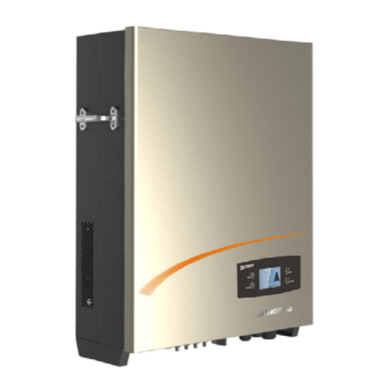
User Manual 2 Product Introduct ion Item Description Remark Smart energy Three-phase electronic energy meter, used to measure meter (optional) the active power output. Communicate with the inverter via RS485 port. Utility grid TT, TN-C, TN-S, TN-C-S. Household load Household appliances. 2.2 Product Description 2.2.1 Inverter Appearance Fig. -
Page 16: Inverter Dimensions
Tab. 2-1 Dimension Values Type W(mm) H(mm) D(mm) Net weight(kg) SG8KTL-EC SG10KTL-E SG12KTL-E 2.2.3 LCD Display Panel As a human-computer interact ion interface, LCD display panel is on the front panel and comprises LED indicators, buttons and LCD screen. ... -
Page 17: Technical Description
User Manual 2 Product Introduct ion Fig. 2-4 LCD Display Panel Name Description LED indicators “RUN” and “FAULT”. The current state can be known from the two indicators. Detailed definition is shown in Tab. 2-2. Buttons User can operate the LCD menu of the inverter via the two buttons. -
Page 18: Functions Description
Zero export (0% feed-in funct ion, opt ional) At the grid-connect ion point, the three-phase SUNGROW Energy Meter is used for measuring the feed-in power. Enable the feed sett ing and set the limit value via the LCD menu. Then the inverter will run with power derat ing once the meter... - Page 19 User Manual 2 Product Introduct ion Protect ion funct ions include: − Short circuit protect ion − Insulat ion resistance detect ion and alarm − Inverter output voltage monitoring − Inverter output frequency monitoring − Residual current monitoring − DC inject ion of AC output current surveillance −...
-
Page 20: Unpacking And Storing
3 Unpacking and Storing 3.1 Unpacking and Inspecting The device is thoroughly tested and inspected before delivery. Although sturdy packaging is used, damage may st ill occur during shipping. If there is visible damage to the packaging or the inner contents, or anything missing, contact the device dealer. -
Page 21: Identifying Inverter
Grid Monitoring: VDE 0126-1-1 VDE-AR-N 4105 Grid Monitoring: VDE 0126-1-1 VDE-AR-N 4105 Grid Monitoring: VDE 0126-1-1 VDE-AR-N 4105 SUNGROW POWER SUPPLY CO., LTD. SUNGROW POWER SUPPLY CO., LTD. SUNGROW POWER SUPPLY CO., LTD. WWW.SUNGROWPOWER.COM MADE IN CHINA WWW.SUNGROWPOWER.COM MADE IN CHINA WWW.SUNGROWPOWER.COM... -
Page 22: Delivery Contents
3 Unpacking and Storing User Manual 3.4 Delivery Contents Fig. 3-3 Delivery Contents *Image shown here is for reference only. Actual product you receive may differ. Item Description Inverter. Wall bracket used to mount inverter onto the wall. Expansion bolts for fastening wall bracket onto concrete wall. Fastener set for installing wall bracket onto metal frame. -
Page 23: Storing The Inverter
If there is more than one inverter to be stored, the maximum layers for original paper packaging are three. After long-term storage, local installer or Service Dept. of SUNGROW should perform a comprehensive test before connect ing the inverter into PV power system. -
Page 24: Securing Inverter To The Wall
4 Securing Inverter to the Wall 4.1 Selecting Installation Location Select ing an opt imal installat ion locat ion for the inverter is decisive for its operat ing safety as well as its expected efficiency and service life. 1. Take the load capacity of the wall into account. The wall (such as concrete wall and metal structure) should be strong enough to hold the weight of the inverter over a long period. - Page 25 User Manual 4 Securing Inverter to the Wall 5. Install the device at eye level for easy buttons operat ion and display reading. 6. It is suggested that the inverter be installed vert ically with upside up for good heat dissipat ion.
- Page 26 4 Securing Inverter to the Wall User Manual 9. The ambient temperature should Max. ambient temperature: range from -25°C to 60°C. The power +60°C output will reduce when the ambient temperature exceeds 45°C. Min. ambient temperature: -25°C 10. The maximum relat ive humidity of chosen installat ion site can reach 100%.
-
Page 27: Moving Inverter To Installation Site
User Manual 4 Securing Inverter to the Wall 13. For mult iple inverters installat ion, posit ion the inverters side by side. For mult i-row inverters installat ion, posit ion the inverters in a staggered arrangement. 14. Do not install the inverter in an enclosed space. Otherwise, the inverter will not operate normally. -
Page 28: Installing The Inverter
4 Securing Inverter to the Wall User Manual 4.3 Installing the Inverter Inverter is installed onto the wall by means of wall bracket in the packaging. 553.3 Fig. 4-1 Dimensions of wall bracket(unit: mm) There are two sets of stainless fasteners supplied to attach the wall bracket to the concrete wall and metal frame respect ively. - Page 29 User Manual 4 Securing Inverter to the Wall In order to avoid electrical shock or other injury, inspect if there is electricity or plumbing installations before drilling holes. Attach the wall bracket to the wall with the supplied expansion bolt set. The torque for fastening the nut should be at least 35 Nm.
- Page 30 4 Securing Inverter to the Wall User Manual On Metal Frame If the chosen mount ing locat ion is metal frame, please proceed as follows to mount the inverter. Remove the supplied wall bracket from the packaging. Choose the best installat ion site according to above requirements. Place the wall bracket onto the chosen metal frame and adjust it unt il it is in a horizontal posit ion.
- Page 31 User Manual 4 Securing Inverter to the Wall grooves on the wall bracket engage perfectly. The Installers must wear gloves to avoid scratches when mounting the inverter. To protect the inverter from theft, you can lock it to the wall bracket with a theft-proof device and a padlock.
-
Page 32: Electrical Connection
5 Electrical Connection Once the inverter is firmly attached to the appropriate locat ion, it can be connected into the PV power system. Improper operation during the wiring process can cause fatal injury to operators or unrecoverable damages to the inverter. Only qualified personnel can perform the wiring work. - Page 33 The maximum open-circuit voltage of each PV string is 1000 V. SolarInfo logger It can be ordered from SUNGROW. Or use compatible logger from Meteo-Control, Solar-Log or Papendorf SE Remote PC User uses this device to monitor the whole PV system.
-
Page 34: Terminals Description
5 Electrical Connect ion User Manual 5.2 Terminals Description All electrical terminals are located at the bottom of the inverter. Fig. 5-2 shows the connect ion area. Enough space around the inverter should be kept for electrical connect ion when choosing the installat ion site. Fig. -
Page 35: Connecting Inverter To Grid
AC Side Circuit Breaker An independent three or four-pole circuit breaker for the inverter must be installed at the output side to ensure that the inverter can be securely disconnected under load. Inverter Type Specification for AC Circuit Breaker SG8KTL-EC SG10KTL-EC SG12KTL-EC... - Page 36 “Technical notes multiple-paralleled grid-connected inverters” in the download area of SUNGROW website). AC Cable Requirements The grid is connected to the inverter via 5 wires (L1, L2, L3, N and PE). Feed-in power is always three-phase via AC terminal at the bottom of the device.
-
Page 37: Assembling Ac Cables To Connector
Single Conductor Cross Total Outer cable Maximu Section diameters m Cable Length Range Recommen Range Recommended SG8KTL-EC/ 4…10 mm² 4…10 mm² 11…20 SG10KTL-EC/ (AWG11…A (AWG11…A SG12KTL-EC WG7) WG7) Withstand ambient temperature; Layout type (inside wall, underground, free air etc.);... -
Page 38: Connecting Inverter To Pv Arrays
5 Electrical Connect ion User Manual Insert appropriate size AC cables into the water-proof terminal. Strip off insulat ion layer of all AC cables. length strip insulat ion approximately 10 mm. Fix all cables ends to the corresponding terminals with the torque of 1 Nm according to markings on the connector, 1:N 2:L1 3:L2... -
Page 39: Pv Inputs Configuration
User Manual 5 Electrical Connect ion Before connecting the PV arrays to the inverter, make sure that the impedances between the positive terminal of the PV string and Earth and the impedances between the negative terminal of the PV string and Earth are larger than 200 Kohm. - Page 40 Open-circuit Short-circuit Type Area Limit Voltage Limit for Current Limit Total Input Each Input for Each Input 28 A SG8KTL-EC 8440 W 1000 V 14 A 28 A SG10KTL-EC 10550 W 1000 V 14 A 30 A SG12KTL-EC 12650 W...
-
Page 41: Assembling Dc Cable To Connector
Open-circuit Short-circuit Total DC Power Type Voltage Limit for Current Limit for Limit for Inverter Each Input Total Input SG8KTL-EC 8440 W 1000 V 42 A SG10KTL-EC 10550 W 1000 V 42 A SG12KTL-EC 12650 W... - Page 42 DC Cable Requirements Type Cross-Section Outer Cable Max. Max. Area Range Diameters Withstand Withstand Voltage Current Same with 4...6 mm SG8KTL-EC 6…9 mm 1000 V short-circuit 11AWG-9AWG current. Same with 4...6 mm SG10KTL-EC 6…9 mm 1000 V short-circuit 11AWG-9AWG current.
-
Page 43: Dc Wiring Procedure
User Manual 5 Electrical Connect ion insulator with t ightening torque Negative Insulator 2.5…3 Nm. Crimp Contact Cable Gland For further assembly and connect ion instruct ion, please visit the webpage of the device manufacturer. 5.5.3 DC Wiring Procedure Make sure that none of the DC or AC cables connected to the inverter is live before the electrical work. - Page 44 5 Electrical Connect ion User Manual Check the cable connect ion of PV strings for the correct polarity and that the open-circuit voltage does not exceed the inverter input limit 1000 V, even under the lowest operat ing temperature. Refer to module specificat ion supplied by module manufacturer for detailed informat ion.
- Page 45 One pair of DC terminals in DC1 input and DC2 input must be short-circuited by Y-type cable connector terminal. (For SG8KTL-EC and SG10KTL-EC) Connect other PV strings in the same procedures if necessary. Unused DC...
-
Page 46: Grounding The Inverter
5 Electrical Connect ion User Manual 5.6 Grounding the Inverter Because of the transform-less design of the inverter, DC positive pole and DC negative pole are not permitted to be grounded. The inverter will not function properly if otherwise. 5.6.1 Grounding System Overview All non-current carrying exposed metal parts of the equipment and other enclosures in the PV power system should be grounded (e.g., PV arrays frame and inverter enclosure). -
Page 47: Second Protective Earth Terminal
User Manual 5 Electrical Connect ion 5.6.2 Second Protective Earth Terminal The inverters are equipped with second protect ive earth terminal as specified in EN 50178. Second PE Terminal There is a PE terminal on the right side of the inverter. You may choose to connect the PE. -
Page 48: Communication Connection
5 Electrical Connect ion User Manual 5.7 Communication Connection 5.7.1 Interfaces Overview All communicat ion terminals are located on the bottom of the inverter. There are two kinds of opt ional connect ion ports on the communicat ion circuit board: RS485 serial communicat ion with RJ45 ports (RS485-1/2) and Ethernet communicat ion with RJ45 ports (NET-1/2). -
Page 49: Rs485 Communication Connection
5.7.2 RS485 Communication Connection If the communicat ion system is equipped with SolarInfo Logger, inverters may be remotely monitored via SolarInfo Bank. SolarInfo logger and RS485-232 converter are opt ional parts and can be ordered from SUNGROW. Pin 3 RS485 RS232... - Page 50 5 Electrical Connect ion User Manual Inverter 1 Inverter 2 Inverter n SolarInfo Logger RS485-1 RS485-2 RS485-1 RS485-2 RS485-1 RS485-2 RS485 120Ω SolarInfo Logger RS232 RS485 Shielding layer is grounded RS485-232 converter Multiple inverters in daisy chain RS485 RS232 RS232 Fig.
- Page 51 User Manual 5 Electrical Connect ion Push the Waterproof Sealing Insert into the cable gland and make sure that all unused cable openings are sealed with dustproof plugs. According to the posit ion of the inverter, repeat step 6 to connect the other network cables to the RS485-1 /RS485-2.
-
Page 52: Ethernet Communication Connection
5 Electrical Connect ion User Manual If you don’t need to connect other cables, fix all fasten screws to the communicat ion terminal lid, push the Waterproof Sealing Insert back to communicat ion ports and t ighten the Thread-Lock Sealing Nut firmly to the cable gland. - Page 53 User Manual 5 Electrical Connect ion Inverter 1 Inverter 2 Inverter n Router/Switch SolarInfo Bank Explorer Webserver Explorer Fig. 5-12 Inverters network connection in daisy chain topology The network communicat ion of the daisy chain is done via the inverter in-built switching chip.
- Page 54 5 Electrical Connect ion User Manual The related parameters settings can be changed only by qualified personnel! RS485 and Ethernet communication connection cannot be used simultaneously their different communication protocols, communication abnormal will occur if otherwise. Ethernet Connection Procedure Loosen all 6 fasten screws on the communicat ion terminal lid and remove the lid.
-
Page 55: Power Control Configuration
User Manual 5 Electrical Connect ion Repeat step 1 to step 7 to connect the other inverters with Network cables. Pull cables outwards to confirm whether they are fastened firmly. Plug the other end of network cables into the sockets of the switch or router, connect the switch or router to a PC. - Page 56 5 Electrical Connect ion User Manual Start Stop Act ive power limitat ion and react ive power rat io sett ing Act ive power limitat ion and power factor sett ing Where there is only one inverter, users can perform default act ive power limitat ion funct ion by connect ing the inverter to the ripple control receiver.
- Page 57 User Manual 5 Electrical Connect ion Item Description Item Description Master inverter 5-conductor connection at digital input Slave inverter Ripple control receiver RS485 connection Grid Fig. 5-15 Connect the ripple control receiver for inverters with Ethernet connections Item Description Item Description Master inverter 5-conductor connection at digital input...
- Page 58 5 Electrical Connect ion User Manual Pull cables outwards to confirm whether they are installed firmly. Connect the four-pole plug to the DI connect ion socket. Connect the ripple control receiver to the inverter according to the terminal assignment. DI2_P DI3_N DI4_P DI1_N...
- Page 59 User Manual 5 Electrical Connect ion DO Relay Configuration The inverter has two DO relays, with funct ions as follows: − DO1: Grounding fault alarm (not configurable) − DO2: Consumer load control The relays are configured as NO (Normally Open) contact by default. The DO2 contact can be used in two different operat ing modes that can be set via the LCD menu of the inverter.
- Page 60 5 Electrical Connect ion User Manual Pull cables outwards to confirm whether they are installed firmly. Connect the three-pole plug to the DO connect ion sockets. The DO2 relay can be configured as NO (by connect ing COM and OFF) or NC (by connect ing COM and ON) contact.
-
Page 61: Visiting And Configuring The Webserver
6 Visiting and Configuring the Webserver 6.1 User and Authority The Webserver provides user permission and installer permission. To avoid two or more persons to change the inverter configurat ions at the same t ime, only one person can login to Webserver at a t ime. Therefore, once a person logs in and does not exit, other person cannot log in anywhere else. -
Page 62: Main Interface
6 Visit ing and Configuring the Webserver User Manual 6.3 Main Interface Fig. 6-1 Webserver-user interface Name Description Status bar Language selection and user login info Device info The serial number of the inverter. Operation information, parameter setting, history record, grid dispatching, output... -
Page 63: Detailed Information
User Manual 6 Visit ing and Configuring the Webserver Tab. 6-1 Explanation of the icons Icon Name Description : Inverter is not in the fault state. Current status The inverter is in fault state (DSP and LCD communication fault, or fault of the inverter.) reduction reduction due to the use of inverter Total runtime... -
Page 64: Parameter Settings
6 Visit ing and Configuring the Webserver User Manual 6.4 Parameter Settings Parameter sett ings include system parameters, operat ing parameters, protect ion parameters, and communicat ion parameters. 6.4.1 System Parameters This interface is to set t ime and total energy adjustment. 6.4.2 Operating Parameters This interface is for Austria and Vorarlberg to set the standby t ime, recovery t ime, insulat ion resistance, act ive power sett ings and react ive power regulat ion. - Page 65 For detailed informat ion, please refer to “10.11 Setting Running Parameter ”. To set the Q(P) or Q(U) parameters, please contact SUNGROW to get the installer authority first.
-
Page 66: Protection Parameters
6 Visit ing and Configuring the Webserver User Manual 6.4.3 Protection Parameters This interface is for Australia to select the company, single protect stage or mult iple protect stage. This interface is for Austria and Vorarlberg to select the grid codes such as voltage, country, single protect stage or mult iple protect stage. -
Page 67: Communication Parameters
“10.12 Setting Protective Parameters ”. To set the abovement ioned protect ion parameters, please contact SUNGROW to get the installer authority first. 6.4.4 Communication Parameters This interface is to set the related communicat ion parameters. The newly set parameters will not be effect ive immediately. -
Page 68: History Record
6 Visit ing and Configuring the Webserver User Manual 6.5 History Record History record includes the running record, fault record, and event record. 6.5.1 Running Record This interface is to search the running informat ion of the inverter. The default display is the running record of the preset day with 10 records in each page. -
Page 69: Event Record
User Manual 6 Visit ing and Configuring the Webserver 6.5.3 Event Record This interface is to view the inverter event records. At most 100 event records can be stored with 10 records in each page. 6.6 Power Control Configuration This interface is to set the grid dispatching parameters. The different statues of four digital inputs are the configurat ion funct ions of corresponding act ions. -
Page 70: Output Node
It is recommended to perform grid dispatching as per default setting of each configuration status. The change of related parameters must be done only by qualified personnel. Any breach may void warranty claims from SUNGROW. 6.7 Output Node This interface is to set the grounding warning and appliance node parameters. For detailed informat ion, please refer to “10.10.4 System Configuration”. -
Page 71: Commissioning
Commissioning Commissioning is a crit ical part for a well-installed PV system, which can protect against fires, injury and electrical shock. 7.1 Inspection before Commissioning Before start ing the inverter, you should check the following items. The inverter is accessible for operat ion, maintenance and service. Re-check that the inverter is firmly installed onto the wall. - Page 72 7 Commissioning User Manual Country select ion screen will prompt. Perform Countries country sett ings with the right two buttons. Detailed button funct ions can be found in “10.1 Description of Button Function”. Press GR_L GR_IS choose country code. Confirm the sett ings by Pressing ENTER.
- Page 73 User Manual 7 Commissioning (Optional) When the country code “AU” and the grid standard “Manual” are selected, Press ENTER to enter the “Pro-Stage” interface. Press choose the correct stage. Press to move cursor and Press to scroll up t ime value.
- Page 74 7 Commissioning User Manual Configure t ime according to the local t ime. Time sett ing is very important, which directly affects data logging. Press to move cursor Ti m e and Press to scroll up t ime value. Confirm the ...
-
Page 75: Disconnecting, Dismantling And Disposing Of The Inverter
8 Disconnecting, Dismantling and Disposing of the Inverter 8.1 Disconnecting the Inverter For maintenance or other service work, the inverter must be switched off. In normal operation, switching off is not necessary. In order to disconnect the inverter from the AC and DC power sources, proceed as follows. -
Page 76: Dismantling The Inverter
8 Disconnect ing, Dismantling and Disposing of the Inverter user manual For further disconnect ion and conductor reconnect ion instruction, please visit the webpage of device manufacturer. 8.2 Dismantling the Inverter Refer to Chapter 4 and Chapter 6 for the inverter dismantling in reverse steps. If necessary, remove the wall bracket from the wall. -
Page 77: Troubleshooting And Maintenance
2. Perform troubleshooting according to fault type in LCD screen. See “9.1.2 Troubleshooting of Faults in LCD Screen”. 3. If it cannot be solved, please contact SUNGROW. 9.1.2 Troubleshooting of Faults in LCD Screen When faults occur, “Fault” state will be shown on the main screen. Press ... - Page 78 SUNGROW Service Dept.. The DC component of 1. Wait a moment for inverter recovery. AC current has exceeded 2. Contact SUNGROW if the fault reoccurs. inverter limit. Inverter has detected 1. Check the PV strings for ground fault. that there is a failure 2.
- Page 79 User Manual 9 Troubleshoot ing and Maintenance Fault code Specification Troubleshooting 4. Contact SUNGROW if the fault reoccurs. inverter detected that there is 1. Wait a moment for inverter recovery. unbalance between the 2. Contact SUNGROW if the fault reoccurs.
- Page 80 9 Troubleshoot ing and Maintenance User Manual Fault code Specification Troubleshooting sampling channel fault. 2. Contact SUNGROW if the fault reoccurs. Phase-S current sampling channel fault. Phase-T current sampling channel fault. Inverter overcurrent hardware protection. 1. Wait a moment for inverter recovery.
- Page 81 3. Check whether the “PE” cable and the N exceeds the set value. cable are well-connected; 4. Wait until the inverter reverts to normal; 5. Contact SUNGROW if the fault reoccurs. Deviation between the 1. Wait a moment for inverter recovery. PV input power and 2.
- Page 82 Fault code here is for SG8KTL-EC and SG10KTL-EC; while for SG12KTL-EC, the fault code is 304 and 305. Fault code here is for SG8KTL-EC and SG10KTL-EC; while for SG12KTL-EC, the fault code is 041. Fault code here is for SG8KTL-EC and SG10KTL-EC; while for SG12KTL-EC, the fault code is 070-071.
-
Page 83: Maintenance
User Manual 9 Troubleshoot ing and Maintenance 9.2 Maintenance 9.2.1 Routine Maintenance Items Methods Period Save data Save the running data, parameters and log Once 100 days to a disk or a file. Visual check damage deformation of the inverter. Check there is any abnormal noise during the running of the inverter. -
Page 84: Maintenance Instruction
Clean the air inlet and outlet with soft brush or vacuum cleaner if necessary. Battery Maintenance There is a button battery on the inner LCD PCB board. Contact SUNGROW Service Dept. to replace the battery when it is end of service life. -
Page 85: Operating The Lcd Menu
10 Operating the LCD Menu 10.1 Description of Button Function Inverter offers two buttons for the user to look up the running informat ion and configure parameters. The two buttons have mult iple funct ions. Please refer to Tab. 10-1 before any operat ion onto inverter. Tab. -
Page 86: Inverter Menu Structure
10 Operat ing the LCD Menu User Manual 10.2 Inverter Menu Structure Fig. 10-1 Menu Tree-English *The menu tree of SG12KTL-EC doesn’t have the submenu “ISO-protect”. -
Page 87: Main Screen
User Manual 10 Operat ing the LCD Menu 10.3 Main Screen If the inverter succeeds in commissioning, LCD display will enter into the main screen, as shown in Fig. 10-2. 001 IP:192.168.1.100 P-ac P(%) 4.000 E-day 日电量 15.6 E-tot 总电量 497600 State 状态... - Page 88 PV connection is correct. If no anomaly is found, please disconnect DC switch and grid switch to restart. If it still does not work, contact SUNGROW. If inverter is in “Fault” state, Press to view mult iple “Current fault” informat ion ...
-
Page 89: Adjusting Contrast
User Manual 10 Operat ing the LCD Menu 10.4 Adjusting Contrast 1. Press to enter into the contrast adjustment screen. 2. Press to increase the sett ing value and press to decrease the value. 3. Press to confirm the contrast sett ing. ENTER The contrast value ranges from 0 to 100. - Page 90 10 Operat ing the LCD Menu User Manual Energy generated each day in this month. Energy generated every month in this year. Total annual generating capacity in the past fifteen years. DC power input: The total input power of PV1 and DC power i nput PV2.
-
Page 91: History Running Information
User Manual 10 Operat ing the LCD Menu P-W: Inverter output active power. P- W 00000W Country: Inverter selected country code. Count r y The power value indicated by each column of the histogram represents the average value of the power during the related unit interval. 10.6 History Running Information 10.6.1 Fault Records Main Screen (Press ENTER)→Menu (Press )→His-inform (Press ENTER)→... -
Page 92: Running Information Records
10 Operat ing the LCD Menu User Manual The inverter can only store at most 100 latest history event records. 10.6.3 Running Information Records Main Screen (Press ENTER)→Menu (Press )→His-inform (Press ×2)→ Run-record (Press ENTER) On the “Run-record” Run- r eoc r d P1/ 2 Hi s - r ec or d display, you can scroll... -
Page 93: Starting And Stopping The Inverter
The parameter sett ings are password-protected. You can see the inverter’s parameters or set the parameters if you input a default password A (111111). You can set all parameters of the inverter if you input a dedicated password B. Please ask SUNGROW or your dealer for this password. Press ENTER to enter into “Menu”... -
Page 94: Button Operation For Parameters Setting
10 Operat ing the LCD Menu User Manual A password confirmat ion screen will occur. Set - par am Press to move cursor right and Press Passwor d: input the password A. 111111 Press ENTER to confirm the password and Set - par am enter the “Set-param”... -
Page 95: Energy Adjustment
User Manual 10 Operat ing the LCD Menu Main Screen (Press ENTER)→Menu screen (Press ×3)→Set-param (Press ENTER)→Enter password 111111 (Press ENTER)→Sys-param (Press ENTER)→ Time (Press ENTER) On the “Time” screen, Press to move the cursor Ti m e right and Press to set the correct date and time. -
Page 96: System Configuration
10 Operat ing the LCD Menu User Manual Main Screen (Press ENTER)→Menu screen (Press ×3)→Set-param (Press ENTER)→Enter password 111111 (Press ENTER)→Sys-param (Press ENTER, Press ×2)→Load default (Press ENTER) Press ENTER to confirm “load default”. Load def aul t Conf i r m r esum e set t i ng? 10.10.4 System Configuration ×3)→Set-param (Press Main Screen (Press ENTER)→Menu screen (Press... -
Page 97: Firmware Version
The lowest power of the inverter to activate the Electri wake function. Wake power SG8KTL-EC: range: 2.4 kW...8 kW, default: 5.6 kW. SG10KTL-EC: range: 3 kW...10 kW, default: 7 kW. SG12KTL-EC: range: 4 kW...12 kW, default: 8.4 kW. The time needed before the relay receives drive signal. -
Page 98: Setting Running Parameter
10 Operat ing the LCD Menu User Manual 10.11 Setting Running Parameter 10.11.1 Main Screen of Run-param ×3)→Set-param (Press Main Screen (Press ENTER)→Menu screen (Press ENTER)→Enter password 111111 (Press ENTER, Press )→Run-param (Press ENTER) “Run-param” Run-param Run-param screen, scroll pages by Standby time 020s Q-Var switch... -
Page 99: Reactive Power Regulation
User Manual 10 Operat ing the LCD Menu Parameter Explanation Default Range Feed Setting Enable/disable For Australia: ON ON/OFF function of limiting For others: OFF the feed power. Feed Power The upper limit value Australia: 0...100% of feed power. 092.0% For others: 100.0% 10.11.2 Reactive Power Regulation The inverter provides react ive power regulat ion funct ion. - Page 100 10 Operat ing the LCD Menu User Manual Tab. 10-5 “Q(P)” Mode Parameters Explanation Parameter Explanation Default Range Upper Power factor of point P1 in the Q(P) mode 0.9…1 curve Lower Output power of point P1 in the Q(P) 0%...50% Power* mode curve (in %) Power factor of point P2 in the Q(P) mode...
-
Page 101: Save P/Q-Set
User Manual 10 Operat ing the LCD Menu Tab. 10-6 “Q(U)” Mode Parameters Explanation Parameter Explanation Default Range Upper Q/Sn Capacitive Q/Sn value of point P1 in the 0%...50% Q(U) mode curve Lower Q/Sn Inductive Q/Sn value of point P4 in the 0%...50% Q(U) mode curve Grid voltage limit (in %) of point P4 in the... -
Page 102: Setting Protective Parameters
10 Operat ing the LCD Menu User Manual 10.12 Setting Protective Parameters Protect ive parameters are designed for the limit value that can trigger the protect ive funct ions of the inverter. Main Screen (Press ENTER)→Menu screen (Press ×3)→Set-param (Press ENTER) →Enter password 111111 (Press ENTER, Press ×2)→Pro-param (Press ENTER) To make protective parameters setting convenient, Countries... - Page 103 User Manual 10 Operat ing the LCD Menu (Optional) When the country code “AU” is selected, Press ENTER enter the “Grid Standard” interface. Press to choose the correct grid standard. Press ENTER to confirm the choice. Countries Grid Standard Country:...
- Page 104 10 Operat ing the LCD Menu User Manual Single-stage Protective Parameters (when the country selection is not “AT”, “VB(DE)”, or “IT”) Pro-param-single If the selected protective parameter type is “Single-stage”, Vgrid-max 276.0V the following submenu will come up. Vgrid-min 184.0V Press ...
-
Page 105: Setting Communication Parameters
User Manual 10 Operat ing the LCD Menu Parameter Explanation Ⅱ-Min -V. time Stage Ⅱ Grid under–voltage (U<<) tripping time Max-F. prot Over-frequency protection Ⅰ-Max-F. grid Stage Ⅰ Grid over-frequency (f>) Ⅰ-Max-F. time Stage Ⅰ Grid over-frequency (f>) tripping time Ⅱ-Max-F. -
Page 106: Setting Pv Configuration Mode
10 Operat ing the LCD Menu User Manual Apply an IP address, subnet mask, default gateway and port number for the inverter from your network administrator. If there is more than one inverter and all the inverters are set to DHCP [OFF], a unique IP address should be assigned to each inverter. -
Page 107: Reactive Power Regulation For Austria And Vorarlberg
User Manual 10 Operat ing the LCD Menu power according to the “Derat ing Slope”. Default derat ing slope (Pm/Hz, Pm is the power before derat ing): 40.00%. Range: 40% ...100%. Note: “Derat ing Slope”* is the power derat ing slope. Power derat ing slope = 100 / (Grid frequency ×... - Page 108 10 Operat ing the LCD Menu User Manual “Q(U)” Mode for Austria and Vorarlberg Run-param The react ive power rat io changes with the grid voltage. Q/Qmax 100.0% Q/Qmax 100.0% Select Q(U) mode and Press ENTER to enter into the Max U Limit 108.0% “Run-param”...
-
Page 109: Protective Parameters Setting For Austria And Vorarlberg
User Manual 10 Operat ing the LCD Menu Q/Sn Upper Q/Qmax Hysteresis U2 Limit Upper U limit Grid voltage Lower U limit U1 Limit Hysteresis Lower Q/Qmax Fig. 10-6 Reactive Power Regulation Curve in Q(U) Mode 10.15.3 Protective Parameters Setting for Austria and Vorarlberg If the “Countries”... - Page 110 10 Operat ing the LCD Menu User Manual Press to select parameter, Press to move cursor Pro-recover right and Press to set the appropriate value. Vmax recover 253.00V Confirm settings by pressing ENTER. Vmin recover 207.0V 50.05Hz Fmax recover 47.52Hz Fmin recover...
- Page 111 User Manual 10 Operat ing the LCD Menu Confirm settings by pressing ENTER and enter the Setting confirmation “Setting confirmation” screen. Country Check all above-mentioned parameter settings. Pro-Stage Single-stage Confirm them by pressing ENTER. Cancel by pressing Grid code and reset. LVRT Confirm above settings? Multi-stage Protective Parameter...
-
Page 112: Special Settings For Italy
10 Operat ing the LCD Menu User Manual Parameter Explanation Ⅰ-Min -F. time Stage Ⅰ Grid under-frequency (f<) tripping time Ⅱ-Min -F. grid Stage Ⅱ Grid under-frequency (f<<) Ⅱ-Min -F. time Stage Ⅱ Grid under-frequency (f<<) tripping time Press to select parameter, Press to move cursor ... -
Page 113: Reactive Power Regulation For Italy
User Manual 10 Operat ing the LCD Menu Note: “Derat ing Slope”* is the power derat ing slope. Power derat ing slope = 100 / (Grid frequency × Frequency derat ing slope). Frequency derat ing slope range: 2% ...5%. Derating Slope 83.33% Default 100% 51.3... - Page 114 10 Operat ing the LCD Menu User Manual Exit from the Q(P) regulation mode Uout** when the grid voltage is below 100% 90%...100% Uout *PA < PB≤ PC ** Uin>Uout Default Curve Deviation No adjustment cosϕ = ± 0,98 That depends on the capacity of the inverter. Fig.
-
Page 115: Protective Parameters Setting For Italy
User Manual 10 Operat ing the LCD Menu Exit from the Q(U) regulation mode Pout** 1%...20% when the power is below Pout Curve Curve type *V2i < V1i < V1s < V2s **Pin > Pout Inductive Inductive Capacitive Capacitive A: Default Fig. - Page 116 10 Operat ing the LCD Menu User Manual Press to select parameter, Press to move cursor Pro-recover right and Press to set the appropriate value. Vmax recover 253.00V Confirm settings by pressing ENTER. Vmin recover 195.5V Fmax recover 50.10Hz Fmin recover 49.90Hz Tab.
- Page 117 User Manual 10 Operat ing the LCD Menu Tab. 10-18 “IT” Multi-stage Protective Parameters Explanation Parameter Explanation Max-V. prote Over-voltage protection Ⅰ-Max-V. grid Stage Ⅰ Grid over-voltage (U>) Ⅰ-Max-V. time Stage Ⅰ Grid over-voltage (U>) tripping time Ⅱ-Max-V. grid Stage Ⅱ Grid over-voltage (U>>) Ⅱ-Max-V.
-
Page 118: Viewing Pv Plant Information
11 Viewing PV Plant Information After registering on the webpage www.solarinfobank.com, users can view PV plant informat ion through the PC or smartphone. Users can also view PV plant informat ion through the APP of SolarInfo Home installed into the smartphone. 11.1 SolarInfo Bank Connection 11.1.1 For Common User Connect the communicat ion cable between router and inverter, and connect... -
Page 119: For Professional User
The inverter is connected directly to The computer cannot visit SolarInfo Bank. Scenario 3 The inverter is connected directly to Contact service engineer of the net port. SUNGROW when the inverter and the PC are in different subnets. SolarInfo Bank Router/Switch Inverter Inverter... - Page 120 11 Viewing PV Plant Informat ion User Manual Connect the communicat ion cable. Set the DHCP to OFF and set the IP address, subnet mask, gateway, DNS1 and DNS2, as shown in the following figure. Acquire the IP, subnet mask, gateway, DNS1 and DNS2 from the network professional.
- Page 121 User Manual 11 Viewing PV Plant Informat ion IP address format: First 9 digitals of the IP address: the same as the first 9 digitals of the inverter IP address. Example: if the inverter IP address is 192.168.001.100, you must input 192.168.001 for the first 9 digitals of computer IP address.
-
Page 122: Registration And Adding Pv Plant
11 Viewing PV Plant Informat ion User Manual 11.2 Registration and Adding PV Plant Open a browser and enter the URL www.solarinfobank.com to view the homepage of SolarInfo Bank. Register a new user by clicking “Register”. The registrat ion interface as shown below will appear .User can select Home Users or Business Users according to real situat ion. - Page 123 User Manual 11 Viewing PV Plant Informat ion Fill in the user informat ion in the following interface. Click Expansion to fill in more informat ion in the following interface. Then click Next. The Country, City, Monetary unit and Temperature unit can be selected from the drop-down list.
- Page 124 11 Viewing PV Plant Informat ion User Manual Fill in the plant informat ion in the following interface. Click Expansion to fill in more informat ion. Click Complete to finish the registrat ion and click Previous to return to the previous page to modify informat ion. If the Home Users is selected in step 2, the registrat ion process is finished by now.
- Page 125 -25°C…+60°C Overvoltage Category III[MAINS],II[PV] Grid Monitoring: VDE 0126-1-1 VDE-AR-N 4105 SUNGROW POWER SUPPLY CO., LTD. WWW.SUNGROWPOWER.COM MADE IN CHINA Proceed as follows to fill in the Device Informat ion if the Business Users is selected in step 2. The format of Serial number, Password, and Device name are the same as that in Step 4.
-
Page 126: Viewing Information Via The App
For iOS Scenario 2 Search for SolarInfo Home in your APP Store to download and install it. solarinfo home Download and Install App Store Search For other smartphones (Android) Scenario 1 The address for downloading SolarInfo Home APP is https://play.google.com/store/apps/details?id=com.sungrow.home.or... - Page 127 User Manual 11 Viewing PV Plant Informat ion Http://www.solarinfobank.com/app/SolarInfoHome_v1.0.apk. You can also use your smartphone to scan the following OR codes to download and install it. For Android Scenario 2 Search for SolarInfo Home in your Play Store to download and install it. Search solarinfo home Download...
-
Page 128: Solarinfo Home App Online Registration
11 Viewing PV Plant Informat ion User Manual 11.3.2 SolarInfo Home APP Online Registration Slide left Slide left SolarInfo Home NOTE Please enter your e-mail account and the password. Slide right(Yes) Next Inverter Nameplate The same as the SN Submit Press HOME button... -
Page 129: Visit In "Remote [Login]"Mode
User Manual 11 Viewing PV Plant Informat ion 11.3.3 Visit in “Remote [Login]”mode The SolarInfo Home APP can be visited only in “Remote [Login]”. In “Remote [Login]” mode, you need configure the inverter to connect it to your router and complete registrat ion. Then you can log into SolarInfo Home via the Internet to view the device running informat ion anywhere. -
Page 130: Appendix
12 Appendix 12.1 Technical Data Parameters SG8KTL-EC SG10KTL-EC SG12KTL-EC Input Side Data Max. PV input power 8440 W 10550 W 12650 W Max. PV input voltage 1000 V Startup voltage 250 V Nominal input voltage 610 V MPP voltage range 200...900 V... - Page 131 User Manual 12 Appendix Parameters SG8KTL-EC SG10KTL-EC SG12KTL-EC Protection Anti-islanding protection short circuit protection Leakage current protection DC switch Integrated DC fuse Overvoltage protection System Max. efficiency 98.0% 98.0% 98.0% Max. European 97.5% 97.6% 97.5% efficiency Isolation method Transformerless Ingress...
-
Page 132: Exclusion Of Liability
Damages caused by irresist ible natural environment The use of supplied software produced by Sungrow Power Supply Co., Ltd. is subject to the following condit ions: Sungrow Power Supply Co., Ltd. rejects any liability for direct or indirect damages arising from the use of the SolarInfo software. -
Page 133: About Us
The power rat ing of SUNGROW products covers from hundred watt to mega-watt systems. The vision of SUNGROW is to help our customers acquire stable and clean power with minimum cost, maximum reliability and enhanced safety.
Need help?
Do you have a question about the SG8KTL-EC and is the answer not in the manual?
Questions and answers