Comeup GTD-2800 Manual
Heavy duty hoist
Hide thumbs
Also See for GTD-2800:
- Introduction (2 pages) ,
- Instruction manual (21 pages) ,
- Manual (2 pages)
Table of Contents
Advertisement
Quick Links
Introduction
Feature
Line lifting:
Wire rope:
Brake:
Control:
Unpacking
H oist assembly..................................................................... 1 pc
. . . .
C ontrol box........................................................................... 1 pc
. . . .
. . . .
R emote control...................................................................... 1 pc
W ire rope with hook................................................................ 1 pc
. . . .
Read this manual carefully
Carefully read and understand this manual before operating the winch.
Careless winch operation may result in personal injury, danger to others and or
damage to property
Information requesting or parts ordering
Please specify the following information:
. . . .
H oist PN
. . . .
S erial number
. . . .
Q uantity for each part
1,270 kg / 2,800 lb wire rope first layer
7.9 mm × 28m galvanized aircraft A7 × 19
Both Mechanical cone brake and permanent motor dynamic
brakes
Handheld pendant switch
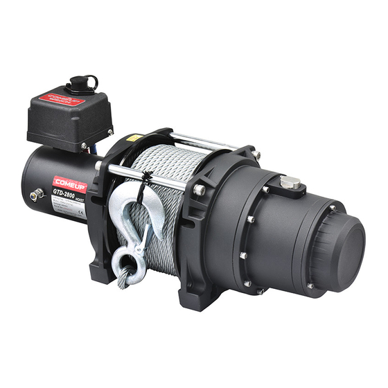
Heavy Duty Hoist
GTD-2800
Model:
. . . .
P art description
. . . .
R eplacement part number
PN: 753022 12V DC
753033 24V DC
Advertisement
Table of Contents

Subscribe to Our Youtube Channel
Related Manuals for Comeup GTD-2800


Summary of Contents for Comeup GTD-2800
- Page 1 Heavy Duty Hoist GTD-2800 Model: PN: 753022 12V DC 753033 24V DC Introduction Feature Line lifting: 1,270 kg / 2,800 lb wire rope first layer Wire rope: 7.9 mm × 28m galvanized aircraft A7 × 19 Brake: Both Mechanical cone brake and permanent motor dynamic...
- Page 2 Installation Before using the winch ensure all electrical components are in good condition and all connections are sound. Hoist mounting . . . . F our (4) M10 x 35L 8.8 grade with 44 N-m torque settings (maximum) high tensile steel bolts must be used in order to sustain the loads imposed on the winch mounting Wire Rope Replacement F eed the end of the wire rope into No.
- Page 3 Wiring Diagram Attach the black lead firmly to the negative (–) battery terminal and red lead to the positive (+) battery terminal. The voltage drop for the winch motor must not exceed 10% of the nominal voltage of 12V/24vdc. Warning T he operator shall always work in compliance with the operating instructions.
- Page 4 Parts List Item No. Description Part No. Motor 12V 882373 Motor 24V 882374 Tie bar kit 882403 Motor support rack 882434 Motor coupling 880047 Drum bushing 880048 Drum kit 882401 Gearbox support rack 882435 shaft 882402 ring gear kit 882436 stage carrier kit 881944 stage carrier kit...
- Page 5 Hoist Assembly (GTD2800)
Need help?
Do you have a question about the GTD-2800 and is the answer not in the manual?
Questions and answers