
Related Manuals for ETC ELTS2


Summary of Contents for ETC ELTS2
- Page 1 Emergency Lighting Transfer System Model: ELTS2 Installation and User Operation Manual Part Number: 1096M1210 Rev: B Released: 2021-07...
- Page 2 To view a list of ET C tr ad e m a r k s a n d p a t e n t s , g o t o etcconnect.com/ip. A l l o t h e r t r a d e m a r k s , b o t h m a r k e d a n d no t m a r k e d , a r e t h e p r o p ert y o f t h ei r r es p e c ti v e o w ne r s .
-
Page 3: Table Of Contents
Warnings and Notice Conventions ....1 Contacting ETC ....... .2 Product Overview . - Page 4 Section 3 How the ELTS2 Works ......29 How the ELTS2 Determines a Power Failure ....29 How Time Delays Work .
-
Page 5: Introduction
Section 1 Introduction Welcome to the Emergency Lighting Transfer System (ELTS2) Installation and User Operation Manual. This manual contains the procedures for safe and efficient installation and user operation of the UL 1008 listed Emergency Lighting Transfer System. Compliance and Standards See the ELTS2 datasheet at etcconnect.com... -
Page 6: Contacting Etc
Contacting ETC If you are having difficulties, and your problem is not addressed by this document, try the ETC support website at support.etcconnect.com or the main ETC website at etcconnect.com. If none of these resources are sufficient, contact ETC Technical Services directly at one of the offices identified below. -
Page 7: Product Overview
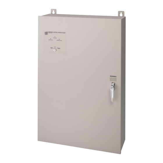
When normal power is restored the ELTS2 reconnects the load to normal power. The local control panel includes a test key switch and LED indicators that clearly display the system status. -
Page 8: Type D (Discrete Feed) Overview
Type D (Discrete Feed) Overview With Type D ELTS2 units, each 20 A emergency circuit (hot and neutral conductors) are independently fed from an adjacent emergency branch circuit breaker panel (by others). Normal 20 A circuits are fed from an adjacent dimmer rack or branch circuit panel. Normal sense power wiring must be run from an external 10–20 A circuit breaker. -
Page 9: Type M (Main Feed) Overview
Type M (Main Feed) Overview With Type M ELTS2 units, emergency mains are connected to phase lugs within the unit. Mains power is distributed through factory wiring to built-in branch circuit distribution and overcurrent protection. Normal 20 A circuits are fed from an adjacent dimmer rack or branch circuit panel. Normal sense power wiring must be run from an external 10–20 A circuit breaker. -
Page 10: Standard Features
• A normally closed dry contact closure is provided for Fire Alarm input. • Up to five remote stations may be used per ELTS2 system. Remote stations include a key switch for switching between normal and emergency states. Each station also includes two LEDs illuminating the active ELTS2 state: Normal Mode or Emergency Mode. -
Page 11: Product Variants
When a phase of the normal power feed connected to the ELTS2 falls below the specified voltage for that phase for the preset amount of time. During a power fail, the ELTS2 will transfer all connected lighting loads to the alternate power source when it is available and stable. -
Page 12: Installation
Installation Requirements Locate the ELTS2 unit in a location where it will not be subject to tampering or vandalism. If possible, install the ELTS2 where it is most secure from damage by fire, flood, or other incident likely to require its use. -
Page 13: Electrical Requirements
Mixing voltages within the ELTS2 may cause system failure. The ELTS2 is available in three base voltages including 120 VAC, 240 VAC, or 277 VAC. 120 VAC / 60 Hz units may be any form of 120 VAC power including: •... -
Page 14: Sense Feed Requirements
The conductors are then pulled through conduit to the ELTS2 unit where they will be connected at the control electronic board (120 VAC units) or the emergency feed transformer (277 VAC units). -
Page 15: Transfer Switch Specification
• If you discover damage be sure to document it to help with the claim to your shipper. • Unpack your order and check the contents against the packing list to be sure your order is complete. • Open the ELTS2 enclosure door and check for loose connections or broken components caused by shipping vibration. Contacting ETC page 2 •... - Page 16 Emergency lighting load output 22–8 AWG terminal strip 1 normal sense feed: Normal power sense must connect to Single-phase or three-phase the ELTS2 through an external 10 A 20–6 AWG (must match normal power feeds) circuit breaker. See Sense Feed Requirements...
- Page 17 ELTS2. 1 normal sense feed: Single- Normal power sense must connect phase or three-phase to the ELTS2 through an external 6–20 AWG Sense NOTE: Must match normal power 10–20 A circuit breaker. See Feed Requirements...
-
Page 18: Install The Elts2
Determine the Installation Location Install the ELTS2 in a location where it will not be subject to tampering or vandalism. If possible, install the ELTS2 where it is secure from damage by fire, flood, or other incident likely to require its use. - Page 19 The installation contractor must follow all local code restrictions. Install NEMA 1 Enclosure WARNING: ELTS2 units are heavy. Be sure you have proper equipment or assistance to lift the unit into place and support it while securing the mounting hardware.
-
Page 20: Rough-In Conduit And Cable
Suivez les procédures de Consignation/Déconsignation appropriées prescrites par la norme NFPA 70E. Requirements for installation vary depending on the type of ELTS2 in your installation (either Type D - Discrete Feed or Type M - Main Feed). See page 12... - Page 21 Rough-In Conduit and Cable for Type D (Discrete Feed) Unit The discrete feed ELTS2 is designed for emergency systems where 20 A emergency branch circuits (hot and neutral conductors only) are fed to the discrete emergency branch circuit terminal strip. Normal 20 A circuits (hot and neutral conductors only) typically fed from an adjacent dimmer rack or circuit breaker panel are wired directly to the normal input side of transfer switch assembly.
- Page 22 Rough-In Conduit and Cable for Type M (Main Feed) Unit The main feed ELTS2 is designed for systems where emergency mains are connected to phase lugs within the ELTS2 unit. Mains power is distributed to the transfer switches, and then to fuses that provide branch circuit protection.
-
Page 23: Connect Emergency Discrete Inputs For Type D (Discrete Feed) Unit
EM24 N EM12 N Note: Discrete ELTS2 systems require external distribution and overload protection (circuit breaker) for each 20 A circuit. Locate the input side of the emergency discrete feed terminal strip. Pull the emergency hot and neutral wires to the terminal strip from the branch circuit panel. Each terminal is clearly labeled with circuit designations. -
Page 24: Connect Emergency Mains For Type M (Main Feed) Unit
2/0–14 AWG 120 in/lb CAUTION: Factory wiring may loosen during transit! Check each of the mains power distribution terminal blocks to ensure that the factory wiring to the transfer switches remains secure after transport. ELTS2 Installation and User Operation Manual... -
Page 25: Connect Wiring
Connect Normal Wires Note: ELTS2 systems require external distribution and overload protection (circuit breaker) for each 20 A circuit. Locate the input side of the transfer switch assembly. Each terminal is clearly labeled with circuit designations. Pull the normal discrete hot and neutral wires to the transfer switch input side. Termination is available for two normal 20 A circuits per transfer switch. -
Page 26: Connect Load Output Wires To The Terminal Strip
Insert the proper wire into the terminal and remove the screwdriver. The wire is held securely in place. Repeat steps 1–5 for the remaining emergency lighting loads in the ELTS2 unit. ELTS2 Installation and User Operation Manual... -
Page 27: Connect 120 Vac Sense Power Wiring
Sense Feed Requirements page 10 for installation requirements. Locate the control electronics board on the top-left side of the ELTS2 enclosure. Pull the normal sense wires to the right side of the control electronics board. Strip the conductors back 3/8”. -
Page 28: Connect 240 And 277 Vac Sense Power Wiring
Sense Feed Requirements page 10 for installation requirements. Locate the two transformers on the top of the ELTS2 sub panel. Pull the normal phase A and neutral sense wire to the right side of the transformers and strip the conductors back 3/8”. -
Page 29: Connect Fire Alarm And Remote Station Wiring
Connect Fire Alarm Wiring A jumper cable is installed in the fire alarm contact input of the ELTS2 when the unit is manufactured. This jumper cable maintains the closed contact input if no fire alarm contact input is installed. Remove this jumper wire only to replace it with dry contact input wiring from the fire alarm system. -
Page 30: Power Up And Check System
• The ELTS2 transfers to Normal Mode only when the normal power source is at or above the Specified Voltage Pickup and Dropout page 29 specified voltage required. - Page 31 Measure the sense feed voltage at the normal power sense feed terminal blocks. Voltage should be within ±10% of the rated voltage for the ELTS2 unit (±10% of 120, 240, or 277 VAC). a: Measure between phase A and neutral.
-
Page 32: Manual Operation
Automatic Operation Test Test the automatic function of the ELTS2 to ensure its ability to switch from normal to emergency power when normal power is interrupted and back again when it is restored. Check the Normal Mode LED on the local station of the ELTS2 is illuminated. -
Page 33: Operation
170 millseconds to 60 seconds. When shipped from the factory, the switches are set to 30 seconds. Both time delays apply to any transfer type in the ELTS2 including Adjust the Power Transfer Delays page 31 loss of power, fire alarm, or system test. -
Page 34: Fire Alarm Contact Input Operation
Fire Alarm Contact Input Operation The ELTS2 has a normally closed dry contact closure for use with a fire alarm input. When the input is opened the connected loads are placed in Emergency Mode and the local station “Fire Alarm”... -
Page 35: Adjust The Power Transfer Delays
Adjust the Power Transfer Delays N-E_delay 1 2 3 4 5 6 Use a sharp point, such as a pick or E-N_delay jeweler’s screwdriver, to move the 1 2 3 4 5 6 switches into the correct On or Off N-E_delay 1 2 3 4 5 6 position. -
Page 36: Test The System
(if stable emergency power is present). Insert the key into the local key switch station on the front of the ELTS2 unit or the remote station. -
Page 37: Fire Alarm Test
Emergency Transfer Delay page Reset the fire alarm. • The Fire Alarm LED and Emergency Power LED on the local station of the ELTS2 will deactivate. • The ELTS2 switches to normal power. The Mode indicator will illuminate and all connected lighting loads will resume normal operation. -
Page 38: Service
Service Preventive Maintenance Regular testing and simple maintenance of your ELTS2 system will result in long service life and reliable Automatic Operation Test page 28 performance. See . Maintain and post a test and maintenance log near the ELTS2 cabinet. -
Page 39: Appendix A Side Mount Hardware Installation
Side Mount Hardware Installation Overview By default, ETC ships the ELTS2 NEMA 1 type unit with top and bottom mounting brackets installed. This document contains instructions for installing the optional side mounting hardware kit (ETC part number 1096K1001) to the ELTS2 cabinet. - Page 40 | Support support.etcconnect.com | Contact etcconnect.com/contactETC © 2021 Electronic Theatre Controls, Inc. | Trademark and patent info: etcconnect.com/ip Product information and specifications subject to change. ETC intends this document to be provided in its entirety. 1096M1210 Rev B Released 2021-07...
Need help?
Do you have a question about the ELTS2 and is the answer not in the manual?
Questions and answers