Table of Contents
Advertisement
Quick Links
Advertisement
Table of Contents

Related Manuals for Advantech PCM-3618


Summary of Contents for Advantech PCM-3618
- Page 1 User Manual PCM-3618 8-port RS-422/485 High-Speed Module...
- Page 2 No part of this manual may be reproduced, copied, translated or transmitted in any form or by any means without the prior written permission of Advantech Co., Ltd. Information provided in this manual is intended to be accurate and reliable. How- ever, Advantech Co., Ltd.
- Page 3 This product has passed the CE test for environmental specifications when shielded cables are used for external wiring. We recommend the use of shielded cables. This kind of cable is available from Advantech. Please contact your local supplier for ordering information.
- Page 4 If one of the following situations arises, get the equipment checked by service personnel: The power cord or plug is damaged. Liquid has penetrated into the equipment. The equipment has been exposed to moisture. PCM-3618 User Manual...
- Page 5 The sound pressure level at the operator's position according to IEC 704-1:1982 is no more than 70 dB (A). Safety Precaution - Static Electricity DISCLAIMER: This set of instructions is given according to IEC 704-1. Advantech disclaims all responsibility for the accuracy of any statements contained herein.Safety Precaution - Static Electricity Follow these simple precautions to protect yourself from harm and the products from damage.
- Page 6 PCM-3618 User Manual...
-
Page 7: Table Of Contents
Specifications .................... 2 Initial Inspection ..................3 Board Layout..................... 3 Card Configuration ..................3 Default Settings..................4 Table 1.1: PCM-3618 Default Configuration........ 4 Chapter Jumper and Switch Settings ....5 Jumper and Switch Settings..............6 Table 2.1: Interrupt Status Register SW1........8 Chapter Software &... - Page 8 PCM-3618 User Manual viii...
-
Page 9: Chapter 1 Overview
Chapter Overview... -
Page 10: Introduction
The PCM-3618 is a PC/104-compatible module with eight individually configurable RS-422/485 ports. It works with PC/104 CPU modules to extend additional RS-2422/ 485 ports. The PCM-3618 also features lots of functions such as high transmission speed of 921.6 kbps, shared IRQ and more. It also provides high-performance 16C550 UART communication chip with 16-byte FIFO to reduce CPU load. -
Page 11: Initial Inspection
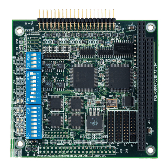
You can use this package to return the card if it should need repair. Board Layout Card Configuration Each port on the PCM-3618 card requires configuration prior to use. The DIP switches set the port to the appropriate I/O address (SW2) and different modes (SW1). The jumpers set the port's IRQ. -
Page 12: Default Settings
Default Settings The board is shipped with default settings. If you need to change these settings, how- ever, see the following sections. Otherwise, you can simply install the card. Table 1.1: PCM-3618 Default Configuration Setting Default Configuration IRQ 5 Speed mode... -
Page 13: Chapter 2 Jumper And Switch Settings
Chapter Jumper and Switch Settings... -
Page 14: Jumper And Switch Settings
Jumper and Switch Settings The PCM-3618 supports ENHANCED mode and SHAREDIRQ functionality. It can fully meet your application needs for high speed and multiple ports. The detail of spe- cific settings are described as follows: Enhanced Mode (M0) In enhanced mode, you can select a different base address. The base address deter- mines the address for each port. - Page 15 Independent IRQ Mode Interrupt Status Register Setup (SW1, Vector Address) This feature on the PCM-3618 is utilized in the shared IRQ. When data arrives at one of the eight ports, an interrupt will be generated in the interrupt register. The PC soft- ware can read this, and identify immediately which port generated the interrupt.
- Page 16 The various DIP switch settings (SW1) for the interrupt status register are shown in the table. Interrupt Register 000H 010H 020H 030H 040H 050H 060H 070H 080H 090H 0A0H 0B0H 0C0H 0D0H 0E0H 0F0H 110H 110H 120H 130H 140H 150H 160H 170H 180H PCM-3618 User Manual...
- Page 17 1B0H 1C0H 1D0H 1E0H 1F0H 200H 210H 220H 230H 240H 250H 260H 270H 280H 290H 2A0H 2B0H 2C0H 2D0H 2E0H 2F0H 300H 310H 320H 330H 340H 350H 360H 370H 380H 390H 3A0H 3B0H 3C0H 3D0H 3E0H 3F0H PCM-3618 User Manual...
- Page 18 Speed Selection The PCM-3618 employs a unique speed option that allows the user to choose either normal speed mode (1x) or high speed mode (8x). Speed mode is selectable at SPEED ofSW2. Normal Speed To select the baud rate commonly associated with COM ports, such as 2400, 4800, 9600? 115.2Kbps, place the switch as follows.
-
Page 19: Chapter 3 Software & Drivers
Chapter Software & Drivers... -
Page 20: Operating Environment Selection
The PCM-3618's driver determines the configuration of the installed cards by reading a data file, GEN-DRV.CNF. When you first install the PCM-3618, and each time you change the card's address and IRQ, you will need to run the card setup program to save the settings to the configuration file. -
Page 21: Icom Utility Setup For Windows 95/98/Nt
300H, then the second port is mapped to 308Hsequentially. PCM-3618 series cards can be installed together in a single system as long as the system memory resources are sufficient and available in a system. Different boards should be assigned different IRQs. -
Page 22: Jumper Setting
Speed: ON (Upper) position High Speed Mode Speed: OFF (Lower) position Normal Speed Mode Operating System Mode Connect the left two pins of JP8 to use DOS, Windows 3.1 Connect the right two pins of JP8 to use Windows 95/98/NT PCM-3618 User Manual... -
Page 23: Signal Wiring
Signal Wiring Connector Pin Assignments You access the PCM-3618's ports through four external maleDB-9 connectors. RS- 422/485 connector pin assignment is as follows : Pin description TX-(DATA-) or received data-(DTE) TX+(DATA+) or received data+(DTE) RX+ or received data+(DTE) RX- or received data-(DTE) - Page 24 RS-422/485 Configuration DATA- RTS- DATA+ RTS+ CTS+ CTS- DATA- RTS- DATA+ RTS+ CTS+ CTS- DATA- RTS- DATA+ RTS+ CTS+ CTS- DATA- RTS- DATA+ RTS+ CTS+ CTS- PCM-3618 User Manual...
-
Page 25: Chapter 4 Hardware Installation
Chapter Hardware Installation... -
Page 26: Hardware Installation
CPU card. Do not tighten too much, or the threads may be damaged. Carefully align the pins of the PCM-3618 with the PC/104connector. Slide the module into the connector. The module pins may not slide all the way into the connector;... - Page 27 PCM-3618 User Manual...
- Page 28 No part of this publication may be reproduced in any form or by any means, electronic, photocopying, recording or otherwise, without prior written permis- sion of the publisher. All brand and product names are trademarks or registered trademarks of their respective companies. © Advantech Co., Ltd. 2007...
Need help?
Do you have a question about the PCM-3618 and is the answer not in the manual?
Questions and answers