Table of Contents

Subscribe to Our Youtube Channel
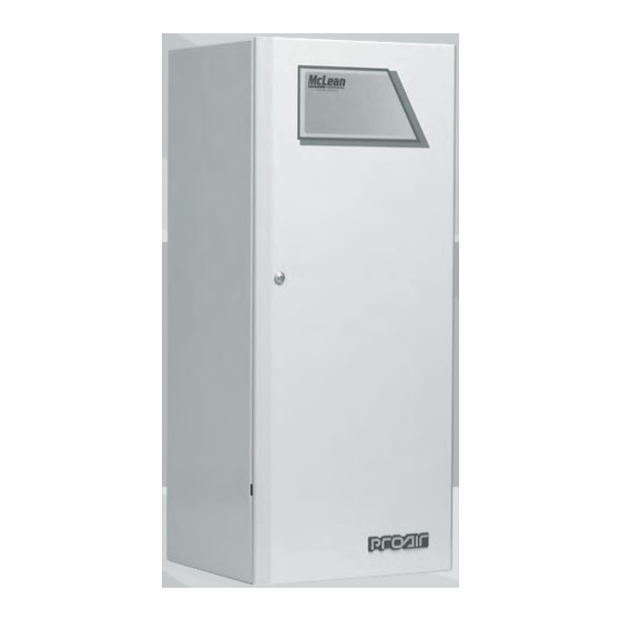
Related Manuals for Pentair McLean Cooling Technology ProAir CR23


Summary of Contents for Pentair McLean Cooling Technology ProAir CR23
- Page 1 INSTRUCTION MANUAL ™ ProAir Air Conditioner CR23 Model Protecting Electronics. Exceeding Expectations. ™ 5736 North Michigan Road Indianapolis, IN 46228 317-257-6811 317-257-1590 fax www.McLeanParts.net 10-1008-16 163- 3-Re Rev.
-
Page 2: Table Of Contents
ProAir CR23 Instruction Manual TABLE OF CONTENTS Receiving the Air Conditioner ................1 Handling and Testing the Air Conditioner ............1 Installation ......................2 System Controls....................2 Design Data, Model Drawing ................3 Components List ....................4 Wire Diagrams ....................5 Temperature Control..................7 Principles of Operation..................7 Maintenance.....................7 Trouble Shooting....................9 NOTE: Some of the information in this manual may not apply if a special unit was ordered. -
Page 3: Installation
Operate the air conditioner for five (5) to ten (10) minutes. No excessive noise or vibration should be evident during this run period. The condenser blower (ambient air), the evaporator blower (enclosure air), and the compressor should be running. Condenser air temperatures should be warmer than normal room temperatures within a few minutes. The compressor is provided with automatic reset thermal overload protection. -
Page 4: Design Data, Model Drawing
ProAir CR23 1600 BTU/Hr. (469 Watts) H x W D: 23" (70584 x 10" (254) x 8.75" (222) Shipping BTU/Hr @ Amps @ BTU/Hr @ Amps @ Amb Temp Weight Model Voltage Phase Lbs/Kgs F/131 F 131 F/131 F 131 F/131 F/95 CR23-0216-GXXX... -
Page 5: Components List
CR23 Components List (Table A) Part Description 115 Volt 230 Volt Blower, Condenser 12-1012-01 12-1012-02 Blower, Evaporator 12-1012-01 12-1012-02 Capacitor, Compressor, Start/Run Compressor 10-1016-61 SP 10-1026-71 SP Thermal Overload, 10-1007-19 10-1007-58 Compressor Filter, Air, Reusable 23-2004-00 23-2004-00 Thermostat, SPST, 55-100F 10-1061-16 10-1061-16 Mounting Gasket Kit... -
Page 6: Wire Diagrams
CR23 Wire Diagram, Level 1 CR23 Wire Diagram, Level 1 with Electric Heat NOTE: For voltage, hertz, and options not shown in this manual, refer to the wiring diagram attached to the unit. 10-1008-163 REV.10 317-257-6811 www.McLeanParts.net 317-257-1590 fax... - Page 7 CR23 Wire Diagram, Level II & III CR23 Wire Diagram, Level II & III with Electric Heat NOTE: For voltage, hertz, and options not shown in this manual, refer to the wiring diagram attached to the unit. 10-1008-163 REV.10 317-257-6811 www.McLeanParts.net 317-257-1590 fax...
-
Page 8: Temperature Control
TEMPERATURE CONTROL The electromechanical thermostat is factory preset to 75 F/23 C. To change the temperature setting, remove the nylon plug from the back face of the unit. Use a standard screwdriver to adjust thermostat. For cooler temperatures turn clockwise, for warmer temperatures turn counterclockwise. PRINCIPLES OF OPERATION If electrical power to the air conditioner is interrupted and reapplied immediately, (within 3 to 5 seconds), the compressor may not restart due to the high back pressure of the compressor. - Page 9 The above described shut-down is symptomatic of a clogged or dirty filter, thus causing a reduction in cooling air flow across the surface of the compressor and condenser coil. Do not run the air conditioner for extended periods of time with the filter removed. Particles of dust, lint, etc., can plug the fins of the condenser coil which will give the same reaction as a plugged filter.
-
Page 10: Trouble Shooting
TROUBLE SHOOTING Basic Air Conditioning Trouble Shooting Check List Check manufacturer’s nameplate located on the unit for correct power supply. Turn the power to the unit on. The evaporator (Enclosure or “COLD” air) fan should come on. Is there airflow? YES, proceed to step # 3. - Page 11 Symptoms and Possible Causes: SYMPTOM POSSIBLE CAUSE Unit won’t cool * Fans not running * Compressor not running * Compressor runs, but has bad valves * Loss of refrigerant Compressor tries to start but won’t run * Low line voltage at start. Should be +/-10% rated voltage * Compressor motor stuck * Bad relay * Bad overload switch...
- Page 12 Protecting Electronics. 5736 North Michigan Road Exceeding Expectations. ™ Indianapolis, IN 46228 317-257-6811 317-257-1590 fax www.McLeanParts.net...
Need help?
Do you have a question about the McLean Cooling Technology ProAir CR23 and is the answer not in the manual?
Questions and answers