
Related Manuals for Pentair SPECTRACOOL G57


Summary of Contents for Pentair SPECTRACOOL G57
-
Page 1: Air Conditioner
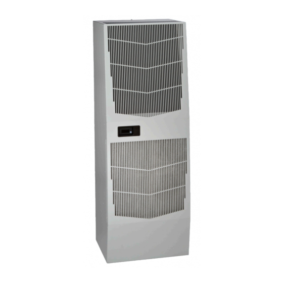
SPECTRACOOL™ Air Conditioner G57 Model INSTRUCTION MANUAL © 2014 Pentair Equipment Protection 89101405 Rev. E P/N 89101402... -
Page 2: Table Of Contents
G57 3-Phase Generic Schematic (actual unit options may vary) .............................20 G57 1-Phase Generic Wire Diagram for Remote Access Control (actual unit options may vary) ...................21 G57 3-Phase Generic Wire Diagram for Remote Access Control (actual unit options may vary) ...................22 DIMENSIONAL DRAWINGS ......................................23... -
Page 3: Receiving The Air Conditioner
HOW TO READ MODEL NUMBERS G150 1. Identifies the type/family of air conditioner and the approximate height (i.e. G57 = Global family about 57 inch high). 2. This is the air conditioner’s listed capacity in BTU/Hr. at rated conditions. (i.e. 20 = 20,000 BTU/Hr. -
Page 4: Technical Information
STANDARD AND OPTIONAL COMPONENT OPERATION THERMOSTAT The G57 air conditioner uses our standard 10-1061-16 thermostat. The thermostat setpoint equals the temperature that the air conditioner turns off. The thermostat has a 10 F differential from setpoint until it calls for cooling or heating. An example of operation is shown below. -
Page 5: Time Delay Relay
SCHEMATICS AND WIRING DIAGRAMS FOR THERMOSTAT CONTROL G57 208V 1-PHASE GENERIC SCHEMATIC (ACTUAL UNIT OPTIONS MAY VARY) 89044386 © 2014 Pentair Equipment Protection... -
Page 6: G57 230V 1-Phase Generic Schematic (Actual Unit Options May Vary)
G57 230V 1-PHASE GENERIC SCHEMATIC (ACTUAL UNIT OPTIONS MAY VARY) 89047070 G57 400/460V 3-PHASE GENERIC SCHEMATIC (ACTUAL UNIT OPTIONS MAY VARY) © 2014 Pentair Equipment Protection 89101405 - 6 -... -
Page 7: G57 208V 1-Phase Generic Wire Diagram (Actual Unit Options May Vary)
G57 208V 1-PHASE GENERIC WIRE DIAGRAM (ACTUAL UNIT OPTIONS MAY VARY) © 2014 Pentair Equipment Protection 89101405 - 7 -... -
Page 8: G57 230V 1-Phase Generic Wire Diagram (Actual Unit Options May Vary)
G57 230V 1-PHASE GENERIC WIRE DIAGRAM (ACTUAL UNIT OPTIONS MAY VARY) © 2014 Pentair Equipment Protection 89101405 - 8 -... -
Page 9: G57 400/460V 3-Phase Generic Wire Diagram (Actual Unit Options May Vary)
G57 400/460V 3-PHASE GENERIC WIRE DIAGRAM (ACTUAL UNIT OPTIONS MAY VARY) © 2014 Pentair Equipment Protection 89101405 - 9 -... -
Page 10: Dimensional Drawings
DIMENSIONAL DRAWINGS 20000 BTU/HR. (G572026GXXX, G572026G2XX) WITH THERMOSTATS 88040022 20000 BTU/HR. (G572046G15X) WITH THERMOSTATS 89059779 © 2014 Pentair Equipment Protection 89101405 - 10 -... -
Page 11: Installation Instructions
INSTALLATION INSTRUCTIONS 1. Inspect the air conditioner and verify correct functionality before mounting the air conditioner. See HANDLING AND TESTING THE AIR CONDITIONER on page 3. 2. Using the mounting gasket kit provided with the unit, install gaskets to the air conditioner, see Figure 1. - Page 12 PARTIAL RECESS MOUNT Figure 1 Cutout Dimensions © 2014 Pentair Equipment Protection 89101405 - 12 -...
-
Page 13: Remote Access Control (Optional)
REMOTE ACCESS CONTROL (OPTIONAL) INTRODUCTION The Remote Access Control is a parametric controller for the complete management of air conditioners. All settings are pre-programmed at the factory. Cooling/heating set-points, cooling/heating differential and high /low temperature alarm set-points can be adjusted by the user. Alarms are outputted through a relay contact and also can be accessed through an Ethernet connection utilizing SNMP, EtherNet/IP and Modbus TCP. -
Page 14: Displaying And Changing Program Variables
DISPLAYING AND CHANGING PROGRAM VARIABLES Access: To view and/or change parameters, press and hold the Prg and Sel buttons for greater than 5 seconds. Press the up or down arrow buttons until “22” is displayed, then press Sel button. When “S-P” is displayed, press Sel. -
Page 15: Alarm Input Connection
ALARM INPUT CONNECTION The Remote Access Control can accept a dry contact/switch input via the two 18 AWG white wires located at the back of the air conditioner. This input is associated with the controller display alarm mnemonic TP (door open and/or smoke detected). -
Page 16: Using The Pc Interface Tool
USING THE PC INTERFACE TOOL The PC Interface Tool gives the user the ability to communicate with the air conditioner unit to read/write parameters using either Ethernet or USB connections. USB COMMUNICATION MODE NOTE: Before connecting unit to the PC, make note of the comm ports present. After the unit is connected to the PC, a new comm port will be added to the list. -
Page 17: Ethernet Communication Mode
ETHERNET COMMUNICATION MODE From Tools menu select Use Ethernet • When Use Ethernet is checked, Comm Port selection is disabled, Device IP and Community boxes are shown and • Ethernet communication can be used. Enter unit’s IP Address and Community string in Device IP and Community boxes at the bottom of the PC Interface •... -
Page 18: Remote Access Control Pin-Out
REMOTE ACCESS CONTROL PIN-OUT FUNCTION NAME PIN # WIRE # COOL ORG78 C1/2 HEAT BRN76 C1/2 ENCL MI BLK77 C3/4 U1 OUTPUTS No4 (na) C3/4 ALARM RELAY OUTPUT YEL39 YEL38 ALARM INPUT CONNECTION WHT63 MALFUNCTION NC SWITCH BLU88 ID3 (na) ID4 (na) ID5 (na) DIGITAL INPUT GROUND... -
Page 19: Schematic And Wiring Diagram For Remote Access Control
SCHEMATIC AND WIRING DIAGRAM FOR REMOTE ACCESS CONTROL G57 1-PHASE GENERIC SCHEMATIC (ACTUAL UNIT OPTIONS MAY VARY) © 2014 Pentair Equipment Protection 89101405 - 19 -... -
Page 20: G57 3-Phase Generic Schematic (Actual Unit Options May Vary)
G57 3-PHASE GENERIC SCHEMATIC (ACTUAL UNIT OPTIONS MAY VARY) © 2014 Pentair Equipment Protection 89101405 - 20 -... -
Page 21: G57 1-Phase Generic Wire Diagram For Remote Access Control (Actual Unit Options May Vary)
G57 1-PHASE GENERIC WIRE DIAGRAM FOR REMOTE ACCESS CONTROL (ACTUAL UNIT OPTIONS MAY VARY) © 2014 Pentair Equipment Protection 89101405 - 21 -... -
Page 22: G57 3-Phase Generic Wire Diagram For Remote Access Control (Actual Unit Options May Vary)
G57 3-PHASE GENERIC WIRE DIAGRAM FOR REMOTE ACCESS CONTROL (ACTUAL UNIT OPTIONS MAY VARY) © 2014 Pentair Equipment Protection 89101405 - 22 -... -
Page 23: Dimensional Drawings
DIMENSIONAL DRAWINGS G57 GENERIC MODEL DRAWING WITH REMOTE ACCESS CONTROL © 2014 Pentair Equipment Protection 89101405 - 23 -... -
Page 24: Installation Instructions With Remote Access Control
INSTALLATION INSTRUCTIONS WITH REMOTE ACCESS CONTROL 1. Inspect the air conditioner and verify correct functionality before mounting the air conditioner. See HANDLING AND TESTING THE AIR CONDITIONER on page 19. 2. Using the mounting gasket kit provided with the unit, install gaskets to the air conditioner, see Figure 2. -
Page 25: Maintenance
MAINTENANCE COMPRESSOR The compressor requires no maintenance. It is hermetically sealed, properly lubricated at the factory and should provide years of satisfactory operating service. Under no circumstances should the access fitting covers be loosened, removed or tampered with. Breaking of seals on compressor access fittings during warranty period will void warranty on hermetic system. Recharging ports are provided for the ease and convenience of reputable refrigeration repair service personnel for recharging the air conditioner. -
Page 26: Condenser And Evaporator Air Movers
CONDENSER AND EVAPORATOR AIR MOVERS Impeller motors require no maintenance. All bearings, shafts, etc. are lubricated during manufacturing for the life of the motor. If one of the condenser impeller motors (ambient impellers) should fail, it is not necessary to remove the air conditioner from the cabinet or enclosure to replace the blower. -
Page 27: Refrigerant Properties Chart (R407C)
REFRIGERANT PROPERTIES CHART (R407C) °F °C Bubble Pt Dew Point °F °C Bubble Pt Dew Point 15.6 117.7 96.8 -37.2 18.3 128.7 106.7 -34.4 21.1 140.2 117.2 -31.7 10.7 23.9 152.5 128.4 -28.9 13.9 26.7 165.5 140.4 -26.1 17.3 29.4 179.2 153.1 -23.3... -
Page 28: Unit Characteristics
UNIT CHARACTERISTICS Model G57-2026-G2XX G57-2026-G1XX G57-2046-GXXX Dimensional Data Height 57.69” / 1465.4 mm Width 20.78” / 527.8 mm Depth 15.28” / 388.1 mm Unit Weight 219 lbs / 99 kg 197 lbs / 89 kg 207 lbs / 94 kg... -
Page 29: Service Data
SERVICE DATA COMPONENTS LIST Part Number Part Description 208 V 1 Phase 230 V 1 Phase 460 V 3 Phase Capacitor, Compressor, Start 10-1032-08 10-1032-08 Capacitor, Compressor, Run 52-6084-09 52-6084-09 Capacitor, Impellers (3) 52-6032-20 52-6032-20 52-6032-20 Coil, Condenser 89057368 89057368 89057368 Coil, Evaporator 52-6010-25... -
Page 30: Trouble Shooting
TROUBLE SHOOTING BASIC AIR CONDITIONING TROUBLE SHOOTING CHECK LIST - THERMOSTAT VERSION 1. Check manufacturer’s nameplate located on the unit for correct power supply. 2. Turn on power to the unit. The evaporator (Enclosure or “COLD” air) impeller should come on. Is there airflow? YES, proceed to step 3. -
Page 31: Symptoms And Possible Causes - Thermostat Version
8. Make sure the coils are clean. Then check evaporator “air in” and “air out” temperatures. If the temperatures are the same: » Possible loss of refrigerant Repair or Replace » Possible bad valves in the compressor defective part 9. To check for a bad thermostat, turn power to the unit off. Remove the upper access panel and place both thermostat wires onto one terminal (replace upper access panel for safety). -
Page 32: Basic Air Conditioning Trouble Shooting Check List - Remote Access Control Version
BASIC AIR CONDITIONING TROUBLE SHOOTING CHECK LIST - REMOTE ACCESS CONTROL VERSION 1. Check manufacturer’s nameplate located on the unit for correct power supply. 2. Turn on power to the unit. The controller will display a start up sequence then revert to the normal temperature display mode. -
Page 33: Symptoms And Possible Causes - Remote Access Control Version
YES, proceed to step 8. NO, possible problem: » Open motor winding(s) » Stuck impeller(s) Repair or Replace » Obstructed wheel(s) defective part » Defective motor capacitor(s) 8. Carefully check the compressor for proper operation - motor should cause slight vibration and the outer case of the compressor should be warm. -
Page 34: Warranty
WARRANTY Pentair Equipment Protection warrants that the Goods manufactured by Pentair Equipment Protection will be free from defects in material and workmanship for a period of one (1) year from the date of shipment by Pentair Equipment Protection, subject to the following conditions and exclusions: A. -
Page 35: Limitation Of Liability
4. Contact information of Buyer that must include: name of company, billing and shipping address, phone, number, fax number, freight carrier and the name and phone number of a Buyer contact who can elaborate on the claimed defect in detail. 5. - Page 36 Pentair Equipment Protection 2100 Ho man Way Minneapolis, MN 55303 USA +1.763.422.2211 +1.763.576.3200 PentairEquipmentProtection.com © 2014 Pentair Equipment Protection 89101405 Rev. E P/N 89101402...
Need help?
Do you have a question about the SPECTRACOOL G57 and is the answer not in the manual?
Questions and answers