Grundfos CUE Installation And Operating Instructions Manual
Hide thumbs
Also See for CUE:
- Installation and operating instructions manual (47 pages) ,
- Safety instructions and other important information (26 pages) ,
- Instructions manual (26 pages)
Advertisement
Quick Links
Advertisement

Subscribe to Our Youtube Channel
Related Manuals for Grundfos CUE


Summary of Contents for Grundfos CUE
- Page 1 GRUNDFOS...
- Page 2 Declaration of conformity We, Grundfos, declare under our sole responsibility that the products CUE, to which this declaration relates, are in conformity with these Council directives on the approximation of the laws of the EC member states: — Low Voltage Directive (2006/95/EC).
- Page 3 Motor cable CUE is a series of external frequency converters especially designed for pumps. Thanks to the start-up guide in the CUE, the installer can quickly Uncontrolled operation (open loop) set central parameters and put the CUE into operation. Controlled operation (closed loop) Connected to a sensor or an external control signal, the CUE will quickly adapt the pump speed to the actual demand.
- Page 4 The CUE contains a large number of mechanical and electronic components. They are all vulnerable to environmental effects. The CUE can also be identified by means of the label on the packaging. The CUE will reduce its performance under these conditions: •...
- Page 5 Ambient temperature up to 50 °C. complete. In case of damage during transport, contact the • Hang the CUE directly on the wall, or fit it with a back plate. transport company to complain. See fig. 3. Note that the CUE is delivered in a packaging which is not suitable for outdoor storage.
- Page 6 The supply voltage and frequency are marked on the CUE nameplate. Make sure that the CUE is suitable for the power supply of the installation site. A mains switch can be installed before the CUE according to local regulations. See fig. 5. ELCB The wires in the terminal box must be as short as possible.
- Page 7 For information about enclosure, see table in section For information about enclosure, see table in section 1. Connect the earth conductor to terminal 99 (PE) on the 1. Fit the mounting plate with two screws. mounting plate. Connect the motor conductors to the terminals 96 (U), 97 (V), 98 (W) of the motor plug.
- Page 8 For information about enclosure, see table in section For information about enclosure, see table in section 1. Connect the earth conductor to terminal 95 (PE). See fig. 12. 1. Connect the earth conductor to terminal 95 (PE). See fig. 14. 2.
- Page 9 For information about enclosure, see table in section For information about enclosure, see table in section 1. Connect the earth conductor to terminal 95 (PE). 1. Connect the earth conductor to terminal 95 (PE). See fig. 18. See figs and 17. 2.
- Page 10 For information about enclosure, see table in section 1. Connect the earth conductor to terminal 95 (PE). Connect the signal cables according to the guidelines for good See figs and 20. practice to ensure EMC-correct installation. See section 2. Connect the mains conductors to the terminals 91 (L1), 92 (L2), 93 (L3).
- Page 11 Access to signal terminals, A4, A5, B1, B2, B3, B4, C1, Required minimum connection, signal terminal C2, C3 and C4 The connection of a thermistor (PTC) in a motor to the CUE requires an external PTC relay. The requirement is based on the fact that the thermistor in the motor only has one layer of insulation to the windings.
- Page 12 NC 2 Normally closed contact Setting contact A54 to current signal "I" One or more CUE units can be connected to a control unit via GENIbus. See the example in fig. 28. Bus Ter = ON Example of an RS-485 GENIbus network The reference potential, GND, for RS-485 (Y) communication must be connected to terminal 61.
- Page 13 Terminals for relay connection, A2 and A3 Terminals for relay connection, B4 Terminals for relay connection, A4, A5, B1 and B2 Terminals for relay connection, C3 and C4, in the upper right corner of the CUE Terminals for relay connection, C1 and C2...
- Page 14 • Connect the screen to frame at both ends for both motor and When the MCB 114 has been installed, the CUE will automatically signal cables. See fig. 40. If the controller has no cable detect if the sensor is Pt100 or Pt1000 when it is switched on.
- Page 15 To meet the EMC requirements, the CUE comes with the following types of built-in radio frequency interference filter (RFI). 1 x 200-240 V * 1.1 - 7.5 kW 3 x 200-240 V 0.75 - 45 kW 3 x 380-500 V 0.55 - 90 kW...
- Page 16 The following operating modes are set on the control panel in Proportional menu OPERATION, display 1.2. See section differential pressure. The differential The pump is running in the control mode pressure is reduced selected at falling flow rate and increased at The pump has been stopped (green indicator rising flow rate.
- Page 17 7/16 16/16 Menu overview The CUE has a start-up guide, which is started at the first start- up. After the start-up guide, the CUE has a menu structure divided into four main menus: gives access to the start-up guide for the general setting of the CUE.
- Page 18 2.10 3.12 2.11 3.13 2.12 3.15 2.13 3.3A 3.16 2.14 3.17 2.15 3.18 2.16 3.19 2.17 3.20 3.21 3.22 3.10 3.23 3.11 3.24...
- Page 19 See fig. 47. The table shows the function of the indicator lights. The control panel is used for local setting of the CUE. The The pump is running or has been stopped by functions available depend on the pump family connected to the a stop function.
- Page 20 Use the start-up guide for the general setting of the CUE including the setting of the correct direction of rotation. Set the rated motor power, P2, according to the motor nameplate: The start-up guide is started the first time when the CUE is • 0.55 - 90 kW connected to the power supply.
- Page 21 The possible settings and the factory setting depend on the pump family. The CUE will give an alarm if the control mode selected requires a sensor and no sensor has been installed. To continue the setting without a sensor, select "Open loop", and proceed. When a sensor has been connected, set the sensor and control mode in menu INSTALLATION.
- Page 22 This test is not suitable for certain pump types and will in certain cases not be able to determine for certainty the correct direction of rotation. In these cases, the CUE changes over to manual setting where the direction of rotation is determined on the basis of the installer’s observations.
- Page 23 The menu makes it possible to return to the start-up guide, which is usually only used during the first start-up of the CUE. The pressure will be shown during the test if a pressure sensor is connected. The motor current is always shown during the test.
- Page 24 CUE, but the pump will not change operating or control mode. It is possible to copy the settings of a CUE and reuse them in another one. Options: •...
- Page 25 This display shows the actual value controlled. If no sensor is connected to the CUE, "-" will appear in the display. This display shows how many times the user has given the lubricated information and when to replace the motor bearings.
- Page 26 MCB 114. The measuring point is selected in display 3.21. Select one of the following control modes: If no sensor is connected to the CUE, "-" will appear in the display. This display is only shown if an MCB 114 sensor input module has been installed.
- Page 27 See section - 0.5 30 + 5L The CUE has two signal relays. In the display below, select in which operating situations the signal relay should be activated. 0.5 * < 5 m: 0.5 * >...
- Page 28 This display appears only if a flowmeter has been configured in display 3.11. The digital inputs of the CUE (terminal 19, 32 and 33) can The display is used for setting the volume for every pulse for the individually be set to different functions.
- Page 29 It is only possible to use the stop function if the system incorporates a pressure sensor, a non-return valve and a diaphragm tank. The stop function can be set to these values: Diaphragm tank • The on/off band can be set to these values: Pressure sensor •...
- Page 30 If it cannot find the other pump, a fault will be indicated. The duty/standby function applies to two pumps connected in parallel and controlled via GENIbus. Each pump must be connected to its own CUE and sensor. The primary targets of the function is the following: •...
- Page 31 This function can be set to these values: • When the function is set to , the CUE will give a warning when the motor bearings are due to be relubricated or replaced. • When the motor bearings have been relubricated or replaced, confirm this action in the above display by pressing "OK".
- Page 32 Ramp-up and ramp-down, display 3.24 Special setup requirements differing from the settings available via the CUE require the use of Grundfos PC Tool E-products. This again requires the assistance of a Grundfos service technician or engineer. Contact your local Grundfos company for more information.
- Page 33 (external fault) At a sensor min. value of 0 bar, a setpoint set via the DI 3 CUE menu of 3 bar and an external setpoint of 80 %, the actual setpoint will be as follows: • (from external sensor) (setpoint set via the CUE menu - sensor min.)
- Page 34 Stop Aut. At a maximum head of 12 metres, a setpoint of Stop Aut. Overload 6 metres set via the CUE menu and an external setpoint of 40 %, Stop Man. the actual setpoint will be as follows: Overload Stop Aut.
- Page 35 In case of fault or malfunction of the CUE, check the alarm list in menu OPERATION. The latest five alarms and latest five warnings can be found in the log menus. Contact a Grundfos technician if an alarm occurs repeatedly.
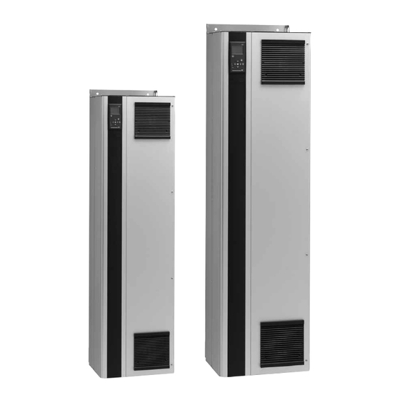
- Page 36 Read from the nameplate: • Supply voltage = 3 x 380-500 V. The individual CUE cabinet sizes are characterised by their • Typical shaft power = 1.5 kW. enclosures. The table shows the relationship of enclosure class • Enclosure class = IP20.
- Page 37 B4, C3, C4 Enclosures A2 and A3 Enclosures A4, A5, B1, B2, B3, B4, C1, C2, C3 and The dimensions are maximum height, width and depth. Relative humidity 5-95 % RH Ambient temperature Max. 50 °C Average ambient temperature over 24 hours Max.
- Page 38 Maximum length, screened motor cable 150 m Maximum length, unscreened motor cable 300 m Maximum length, signal cable 300 m Maximum cable cross-section to signal 1.5 mm terminals, rigid conductor Maximum cable cross-section to signal 1.0 mm terminals, flexible conductor Minimum cable cross-section to signal 0.5 mm terminals...
- Page 39 Screened motor cable, unscreened supply cable. American Wire Gauge.
- Page 40 Approx. 4 k All digital inputs are galvanically separated from the supply voltage (PELV) and other high-voltage terminals. The sound pressure of the CUE is maximum 70 dB(A). The sound pressure level of a motor controlled by a frequency , terminal number...
- Page 43 A-5082 Grödig/Salzburg Telefax: +60-3-5569 2866 Telefax: +34-91-628 0465 Tel.: +43-6246-883-0 GRUNDFOS GMBH Telefax: +43-6246-883-30 Schlüterstr. 33 Bombas GRUNDFOS de México S.A. de GRUNDFOS AB 40699 Erkrath C.V. Box 333 (Lunnagårdsgatan 6) N.V. GRUNDFOS Bellux S.A. Tel.: +49-(0) 211 929 69-0 Boulevard TLC No.
- Page 44 Thinking ahead makes it possible Innovation is the essence 0311 The name Grundfos, the Grundfos logo, and the payoff Be–Think–Innovate are registrated trademarks Repl. 96706951 0609 owned by Grundfos Management A/S or Grundfos A/S, Denmark. All rights reserved worldwide. www.grundfos.com...
Need help?
Do you have a question about the CUE and is the answer not in the manual?
Questions and answers