
Related Manuals for Leadshine iSS57


Summary of Contents for Leadshine iSS57
- Page 1 Hardware Installation Manual iSS57 Integrated Stepper Servo Motors www.leadshine.com HWMN-iSS57-R20120411...
- Page 2 Leadshine reserves the right to make changes without further notice to any products herein to improve reliability, function or design. Leadshine does not assume any liability arising out of the application or use of any product or circuit described herein; neither does it convey any license under its patent rights of others.
- Page 3 Read this manual carefully before trying to install the stepper drive into your system. The person setup the stepper drive should have a better understanding on electronics and mechanics. Contact Leadshine technical guys when have questions on this document. Notice Make sure the power supply voltage dose not exceed the drive’s input range.
-
Page 4: Table Of Contents
Protection Indications ............................12 10. Frequently Asked Questions ............................ 13 Problem Symptoms and Possible Causes ......................13 Warranty ..................................14 Exclusions ................................14 Obtaining Warranty Service ..........................14 Warranty Limitations ............................. 14 Shipping Failed Product ............................14 Contact Us ..................................15 HWMN-ISS57-R20120411... -
Page 5: Family Overview
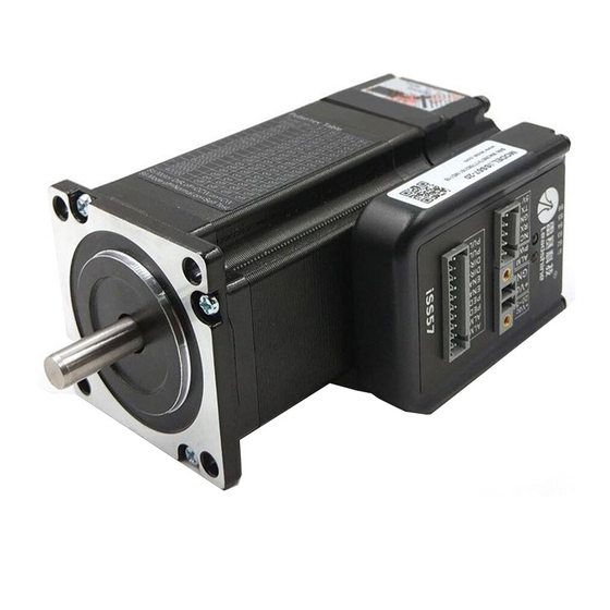
The iSS57 offers an alternative for applications requiring high performance and compact size. Its great feature of fast response and no hunting make it ideal for applications such as bonding and vision systems in which rapid motions with a short distance are required and hunting would be a problem. -
Page 6: Mechanical Specifications
Series Integrated Stepper Servo Hardware Installation Manual Mechanical Specifications Holding Motor Length of Part Number Weight Torque Length ( L) Motor + Drive iSS57-10 1.0Nm 56mm 87.65mm 800g iSS57-20 2.0Nm 80mm 111.65mm 1280 g Elimination of Heat Drive’s reliable working temperature(case) should be <70 (158℉), and motor working temperature(surface) should be <80 (176℉);... -
Page 7: Connectors And Pin Assignment
Series Integrated Stepper Servo Hardware Installation Manual 2. Connectors and Pin Assignment The iSS57 has three connectors, connector for control signals connections, connector for RS232 communication connections and connector for power connections. Control Signal Connector Power Input Connector RS232 Communication Connector The control signal inputs include PULSE, DIRECTION and ENABLE and the control signal outputs include PED (In-position) and ALARM. - Page 8 A PC with at least one serial port is required. You can copy the software either from http://www.leadshine.com or form Leadshine CD. See the detail in software manual. RS232 Communication Connector Pin Name Description +5V power output ( Note: Do not connect it to PC’s serial port)
-
Page 9: Control Signal Requirement
Control Mode and Sequence Chart By default the iSS57 series integrated motor supports Pulse/Direction control mode. If CW/CCW control mode is needed, you can use the PC software to change it. See more information in the software manual. In order to avoid... -
Page 10: Connecting Control Signal
Series Integrated Stepper Servo Hardware Installation Manual 4. Connecting Control Signal The iSS57 accepts both differential and single-ended inputs (including open-collector and PNP output). Choose suitable connections type according to the controller type. Make sure the output port of the controller can sink or source at least 10mA current for the input isolated opto-coupler. -
Page 11: Output Signal Connections
Series Integrated Stepper Servo Hardware Installation Manual Controller Output Signal Connections Drive The iSS57 integrated stepper offers the PED+ PED (in-position) signal to indicate the In-Position achievement of target position. The ALM PED- signal will be active when the integrated ALM+ stepper goes into error. -
Page 12: Recommended Supply Voltage
Driver Lower Input limit Driver Input Voltage Driver Input Voltage Power Supply Voltage Power Supply Voltage Recommended Supply Voltage Both Leadshine’s regulated and unregulated power supply has been designed specially for motion control. Model Voltage Range Typical Voltage Leadshine Power Supply iSS57-10... -
Page 13: Rs232 Communication Connections
Series Integrated Stepper Servo Hardware Installation Manual iSS57 Controller 270O PUL+ PUL- Pulse 270 O DIR+ DIR- Direction 270 O ENA+ ENA- Enable ALM+ Alarm ALM- Pend+ In-Positon Pend- +Vdc 20 ~ 45VDC In order to improve anti-interference performance of the drive, it is recommended to use twisted pair shield cable. -
Page 14: Configuring The Drive
iSS Series Integrated Stepper Servo Hardware Installation Manual 8. Configuring the Drive Introduction There is only one DIP switch to select the micro step resolution, change motor direction and active edge of pulse edge. The motor current will be adjusted dynamically according to load condition. Micro Step Resolution Steps/Revolution Software Configured... -
Page 15: Micro Step Resolution Selection
One is the holding current percentage and the other is the close-loop current percentage. When there is no pulse sent to the drive, iSS57 goes into idle state and the actual motor current is determined by the holding current percentage. -
Page 16: Protection Functions
9. Protection Functions To improve reliability, the iSS57 incorporates some built-in protection functions. The Integrated stepper uses one red LED to indicate the protection type. The periodic time of red is 4 s (seconds), and the blinking times of red LED indicates what protection has been activated. -
Page 17: Frequently Asked Questions
iSS Series Integrated Stepper Servo Hardware Installation Manual 10. Frequently Asked Questions In the event that your drive doesn’t operate properly, the first step is to identify whether the problem is electrical or mechanical in nature. The next step is to isolate the system component that is causing the problem. As part of this process you may have to disconnect the individual components that make up your system and verify that they operate independently. -
Page 18: Warranty
Leadshine Technology Co., Ltd. warrants its products against defects in materials and workmanship for a period of 12 months from shipment out of factory. During the warranty period, Leadshine will either, at its option, repair or replace products which proved to be defective. -
Page 19: Contact Us
86-755-2641-7617 (for America areas) Fax: 86-755-2640-2718 Email: sales@leadshine.com. Technical Support: Tel: 86-755-2641-8447, 86-755-2641-8774, 86-755-2641-0546 Fax: 86-755-2640-2718 Email: tech@leadshine.com(for All) Leadshine America, Inc. Address: 25 Mauchly, Suite 318 Irvine, California 92618 Tel: 1-949-608-7270 Fax: 1-949-608-7298 Web: http://www.leadshineUSA.com Email: sales@leadshineUSA.com and support@leadshineUSA.com.
Need help?
Do you have a question about the iSS57 and is the answer not in the manual?
Questions and answers