Table of Contents
Advertisement
Quick Links
Hardware Installation Manual
IES Series
Part Number
IES
Frame Size
17: 42mm
23 :57mm
24: 60mm
www.leadshine.com
HWMN-IES-R20121030
Integrated Easy Servos
Branch Series
Torque
Blank: Standard
09: 0.9Nm
A: Branch Series A 20: 2.0Nm
B: Branch Series B 40: 4.0Nm
...
...
Communication
Custom-built
Blank: Standard
Blank: Standard
485: RS485
...
CAN: CANOpen
...
Advertisement
Table of Contents

Related Manuals for Leadshine IES Series


Summary of Contents for Leadshine IES Series
- Page 1 Hardware Installation Manual IES Series Integrated Easy Servos Part Number Frame Size Branch Series Torque Communication Custom-built 17: 42mm Blank: Standard 09: 0.9Nm Blank: Standard Blank: Standard 23 :57mm A: Branch Series A 20: 2.0Nm 485: RS485 24: 60mm B: Branch Series B 40: 4.0Nm CAN: CANOpen …...
- Page 2 Leadshine reserves the right to make changes without further notice to any products herein to improve reliability, function or design. Leadshine does not assume any liability arising out of the application or use of any product or circuit described herein; neither does it convey any license under its patent rights of others.
- Page 3 Read this manual carefully before trying to install the stepper drive into your system. The person setup the stepper drive should have a better understanding on electronics and mechanics. Contact Leadshine technical guys when have questions on this document. Notice Make sure the power supply voltage dose not exceed the drive’s input range.
-
Page 4: Table Of Contents
Table of Contents 1. Family Overview ................................. 1 Introduction ................................1 Applications ................................1 Product Covered ..............................2 Mechanical Specifications ............................2 Elimination of Heat ..............................2 2. Connectors and Pin Assignment ..........................3 3. Control Signal Requirement ............................5 Control Mode and Sequence Chart.......................... -
Page 5: Family Overview
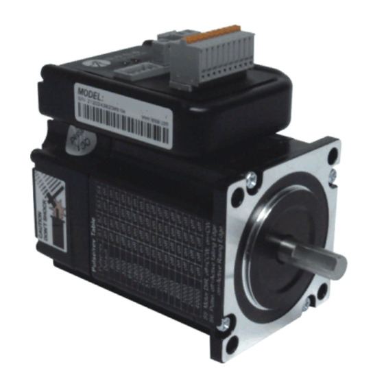
1. Family Overview Introduction Leadshine’s IES integrated easy servo motor is a stepper motor integrated with a 1,000-line (4,000 PPR) encoder and a hybrid servo drive. At very compact size and with all components integrated, the IES can save mounting space, eliminate encoder connection &... -
Page 6: Product Covered
Hardware Installation Manual of the IES Series Product Covered This manual covers the Leadshine integrated easy servo products as shown in the following table: Motor Part Input Pulse Control Pulse Output Holding Number Voltage Voltage Mode Frequency Torque Pulse/Direction In-position... -
Page 7: Connectors And Pin Assignment
Hardware Installation Manual of the IES Series · It is recommended to mount the integrated in a space allowing air flow for good heat conduction. Use forced cooling method to cool the system if necessary. 2. Connectors and Pin Assignment The IES23 has three connectors, a connector for control signals connections, a connector for RS232 communication connections and a connector for power connections. - Page 8 A PC with at least one serial port is required. You can copy the software either from http://www.leadshine.com or form Leadshine CD. See the detail in software manual. RS232 Communication Connector Pin Name Description +5V power output ( Note: Do not connect it to PC’s serial port)
-
Page 9: Control Signal Requirement
Hardware Installation Manual of the IES Series 3. Control Signal Requirement Control Mode and Sequence Chart By default the IES integrated motor supports Pulse/Direction control mode. If CW/CCW control mode is needed, you can use the PC software to change it. See more information in the software manual. In order to avoid problems... -
Page 10: Connecting Control Signal
Hardware Installation Manual of the IES Series 4. Connecting Control Signal The IES accepts both differential and single-ended inputs (including open-collector and PNP output). Choose suitable connections type according to the controller type. Make sure the output port of the controller can sink or source at least 10mA current for the input isolated opto-coupler. -
Page 11: Output Signal Connections
Hardware Installation Manual of the IES Series Output Signal Connections Controller Drive The IES integrated stepper offers the PED (in-position) signal indicate PED+ achievement of target position. The ALM In-Position signal will be active when the integrated PED- stepper goes into error. The output of PED... -
Page 12: Selecting Supply Voltage
Driver Lower Input limit Driver Input Voltage Driver Input Voltage Power Supply Voltage Power Supply Voltage Recommended Supply Voltage Both Leadshine’s regulated and unregulated power supply has been designed specially for motion control. Model Voltage Range Typical Voltage Leadshine Power Supply IES-2309... -
Page 13: Typical Connections
Hardware Installation Manual of the IES Series 6. Typical Connections Typical connections of IES-23xx for NPN control signal is as follows. IES-23XX Controller VCC = 5 - 24V 270O PUL+ PUL- Pulse 270 O DIR+ DIR- Direction 270O ENA+ ENA-... -
Page 14: Configuring The Drive
The motor current will be adjusted dynamically according to load condition. Micro step resolution of the IES can be configured via a 4-bit DIP switch, or Leadshine’s tuning software ProTuner. When all bits of the DIP switch are at “ON” positions, the integrated hybrid servo drive board will take the micro step resolution setting set by the software (4000 by default). -
Page 15: Micro Step Resolution Selection
They should be good enough for most industrial applications, and there is no need to tune them. However, if you want to fine tune the IES for best performance for your applications, Leadshine also offers tuning software, ProTuner, which allows you to adjust those current-loop and position-loop parameters (see software manual). -
Page 16: Protection Functions
Hardware Installation Manual of the IES Series 9. Protection Functions To improve reliability, the IES incorporates some built-in protection functions. The Integrated stepper uses one red LED to indicate the protection type. The periodic time of red is 4 s (seconds), and the blinking times of red LED indicates what protection has been activated. -
Page 17: Frequently Asked Questions
Hardware Installation Manual of the IES Series 10. Frequently Asked Questions In the event that your drive doesn’t operate properly, the first step is to identify whether the problem is electrical or mechanical in nature. The next step is to isolate the system component that is causing the problem. As part of this process you may have to disconnect the individual components that make up your system and verify that they operate independently. -
Page 18: Warranty
Leadshine Technology Co., Ltd. warrants its products against defects in materials and workmanship for a period of 12 months from shipment out of factory. During the warranty period, Leadshine will either, at its option, repair or replace products which proved to be defective. -
Page 19: Contact Us
Hardware Installation Manual of the IES Series Contact Us China Headquarters Address: 3/F, Block 2, Nanyou Tianan Industrial Park, Nanshan District Shenzhen, China Web: http://www.leadshine.com Sales Hot Line: Tel: 86-755-2641-7674 (for Asia, Australia, Africa region) 86-755-2640-9254 (for Europe region) 86-755-2641-7617 (for America region) Fax: 86-755-2640-2718 Email: sales@leadshine.com.
Need help?
Do you have a question about the IES Series and is the answer not in the manual?
Questions and answers