Table of Contents
Advertisement
Quick Links
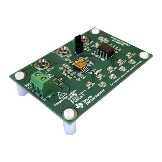
INA901EVM-CVAL Evaluation Module User's Guide
This user's guide describes the characteristics, operation, and use of the INA901EVM-CVAL evaluation
module (EVM). This EVM is designed to evaluate the performance of the INA901-SP voltage-output,
current shunt monitor in a variety of configurations. Throughout this document, the terms evaluation board,
evaluation module, and EVM are synonymous with the INA901EVM-CVAL. This document also includes a
schematic, reference printed-circuit board (PCB) layouts, and a complete bill of materials (BOM).
Danger: HIGH VOLTAGE! This evaluation board is intended for
professional use only. It has exposed high voltages. Do not
operate this board without proper high-voltage/high-current safety
practices. Read the
Evaluation (TI HV EVM) User Safety Guidelines
the EVM.
SBOU216A – October 2018 – Revised June 2020
Submit Documentation Feedback
WARNING
General Texas Instruments High Voltage
Copyright © 2018–2020, Texas Instruments Incorporated
SBOU216A – October 2018 – Revised June 2020
section before using
INA901EVM-CVAL Evaluation Module User's Guide
User's Guide
1
Advertisement
Table of Contents

Related Manuals for Texas Instruments INA901EVM-CVAL


Summary of Contents for Texas Instruments INA901EVM-CVAL
- Page 1 Throughout this document, the terms evaluation board, evaluation module, and EVM are synonymous with the INA901EVM-CVAL. This document also includes a schematic, reference printed-circuit board (PCB) layouts, and a complete bill of materials (BOM).
-
Page 2: Table Of Contents
Contents ...... General Texas Instruments High Voltage Evaluation (TI HV EVM) User Safety Guidelines ........................Overview ....................INA901-SP Overview ..................INA901EVM-CVAL Overview ....................EVM Kit Contents .............. Related Documentation From Texas Instruments ........................Hardware ......................Features ........................Operation ...................... -
Page 3: General Texas Instruments High Voltage Evaluation (Ti Hv Evm) User Safety Guidelines
Any other use and/or application are strictly prohibited by Texas Instruments. If you are not suitable qualified, you should immediately stop from further use of the HV EVM. -
Page 4: Overview
8-pin CFP package. INA901EVM-CVAL Overview The INA901EVM-CVAL is designed to demonstrate the functionality and performance of the INA901-SP. The board contains a footprint for a size 2512 surface mount shunt resistor. It can also be operated with an external shunt resistor or by simply applying differential voltages to the inputs. -
Page 5: Hardware
4.1.1 High Voltage The common-mode voltage rating of the INA901-SP and the INA901EVM-CVAL is –15 V to 65 V. When using the device and EVM under such circumstances, all proper safety practices must be followed. Do not apply less than –15 V or more than 65 V. -
Page 6: Measurements
The shunt resistor will become hot during use. Ensure proper precautions are taken to prevent contact with R1 during operation. Failure to do so can result in personal injury. INA901EVM-CVAL Evaluation Module User's Guide SBOU216A – October 2018 – Revised June 2020 Submit Documentation Feedback... -
Page 7: High-Side Setup Using Onboard Shunt Resistor
CMP_OUT. Slowly increase the magnitude of the load current until it measures > 125 mV. Observe the comparator output change states. SBOU216A – October 2018 – Revised June 2020 INA901EVM-CVAL Evaluation Module User's Guide Submit Documentation Feedback Copyright © 2018–2020, Texas Instruments Incorporated... -
Page 8: High-Side Setup Using An External Shunt Resistor
Step 5. Observe the overcurrent trigger: Using either a DMM or oscilloscope, measure the voltage at CMP_OUT. Slowly increase the magnitude of the load current until it measures > 125 mV. Observe the comparator output change states. INA901EVM-CVAL Evaluation Module User's Guide SBOU216A – October 2018 – Revised June 2020 Submit Documentation Feedback... -
Page 9: Supply Setup For Common And Differential Voltage
CMP_OUT. Slowly increase the magnitude of the load current until it measures > 125 mV. Observe the comparator output change states. SBOU216A – October 2018 – Revised June 2020 INA901EVM-CVAL Evaluation Module User's Guide Submit Documentation Feedback Copyright © 2018–2020, Texas Instruments Incorporated... -
Page 10: Evm Components
Input Current J1 is the primary input terminal of the INA901EVM-CVAL. This terminal allows the EVM to be placed in series with a bus voltage and load current. R1 is able to be fitted with a size 2512 resistor in this use case. -
Page 11: Schematic, Pcb Layout, And Bill Of Materials
100pF INA901HKX/EM 100V BUF_IN PRE_OUT 15pF CMPB_OUT 10.0M CMPB_IN- CMPB_IN+ GND GND GND 10.0k Figure 4. INA901EVM-CVAL Schematic SBOU216A – October 2018 – Revised June 2020 INA901EVM-CVAL Evaluation Module User's Guide Submit Documentation Feedback Copyright © 2018–2020, Texas Instruments Incorporated... -
Page 12: Pcb Layer Plots
PCB Layer Plots Figure 5 through Figure 8 illustrate the INA901EVM-CVAL PCB layouts. Figure 5. INA901EVM-CVAL Top Overlay INA901EVM-CVAL Evaluation Module User's Guide SBOU216A – October 2018 – Revised June 2020 Submit Documentation Feedback Copyright © 2018–2020, Texas Instruments Incorporated... -
Page 13: Ina901Evm-Cval Top Copper
Schematic, PCB Layout, and Bill of Materials www.ti.com Figure 6. INA901EVM-CVAL Top Copper SBOU216A – October 2018 – Revised June 2020 INA901EVM-CVAL Evaluation Module User's Guide Submit Documentation Feedback Copyright © 2018–2020, Texas Instruments Incorporated... -
Page 14: Ina901Evm-Cval Bottom Copper
Schematic, PCB Layout, and Bill of Materials www.ti.com Figure 7. INA901EVM-CVAL Bottom Copper INA901EVM-CVAL Evaluation Module User's Guide SBOU216A – October 2018 – Revised June 2020 Submit Documentation Feedback Copyright © 2018–2020, Texas Instruments Incorporated... -
Page 15: Ina901Evm-Cval Bottom Overlay
Schematic, PCB Layout, and Bill of Materials www.ti.com Figure 8. INA901EVM-CVAL Bottom Overlay SBOU216A – October 2018 – Revised June 2020 INA901EVM-CVAL Evaluation Module User's Guide Submit Documentation Feedback Copyright © 2018–2020, Texas Instruments Incorporated... -
Page 16: Bill Of Materials
Schematic, PCB Layout, and Bill of Materials www.ti.com Bill of Materials Table 2 lists the INA901EVM-CVAL bill of materials. NOTE: This evaluation kit contains Pb, a necessary component for QML parts. Table 2. INA901EVM-CVAL Bill of Materials Description Designator Part Number... - Page 17 NOTE: Page numbers for previous revisions may differ from page numbers in the current version. Changes from Original (October 2018) to A Revision ....................Page ....................• Sample History element for revision A. SBOU216A – October 2018 – Revised June 2020 Revision History Submit Documentation Feedback Copyright © 2018–2020, Texas Instruments Incorporated...
- Page 18 STANDARD TERMS FOR EVALUATION MODULES Delivery: TI delivers TI evaluation boards, kits, or modules, including any accompanying demonstration software, components, and/or documentation which may be provided together or separately (collectively, an “EVM” or “EVMs”) to the User (“User”) in accordance with the terms set forth herein.
- Page 19 www.ti.com Regulatory Notices: 3.1 United States 3.1.1 Notice applicable to EVMs not FCC-Approved: FCC NOTICE: This kit is designed to allow product developers to evaluate electronic components, circuitry, or software associated with the kit to determine whether to incorporate such items in a finished product and software developers to write software applications for use with the end product.
- Page 20 www.ti.com Concernant les EVMs avec antennes détachables Conformément à la réglementation d'Industrie Canada, le présent émetteur radio peut fonctionner avec une antenne d'un type et d'un gain maximal (ou inférieur) approuvé pour l'émetteur par Industrie Canada. Dans le but de réduire les risques de brouillage radioélectrique à...
- Page 21 www.ti.com EVM Use Restrictions and Warnings: 4.1 EVMS ARE NOT FOR USE IN FUNCTIONAL SAFETY AND/OR SAFETY CRITICAL EVALUATIONS, INCLUDING BUT NOT LIMITED TO EVALUATIONS OF LIFE SUPPORT APPLICATIONS. 4.2 User must read and apply the user guide and other available documentation provided by TI regarding the EVM prior to handling or using the EVM, including without limitation any warning or restriction notices.
- Page 22 Notwithstanding the foregoing, any judgment may be enforced in any United States or foreign court, and TI may seek injunctive relief in any United States or foreign court. Mailing Address: Texas Instruments, Post Office Box 655303, Dallas, Texas 75265 Copyright © 2019, Texas Instruments Incorporated...
- Page 23 TI products. TI’s provision of these resources does not expand or otherwise alter TI’s applicable warranties or warranty disclaimers for TI products. Mailing Address: Texas Instruments, Post Office Box 655303, Dallas, Texas 75265 Copyright © 2020, Texas Instruments Incorporated...
Need help?
Do you have a question about the INA901EVM-CVAL and is the answer not in the manual?
Questions and answers