Table of Contents
Advertisement
Quick Links
With an input operating voltage as low as 3.5 V and up to 100 V as specified in
LM5140/1/3/6-Q1 family of automotive synchronous buck controllers from TI provides flexibility, scalability,
and optimized solution size for a range of applications. These controllers enable DC/DC solutions with
high density, low EMI, and increased flexibility. All controllers are rated for a maximum operating junction
temperature of 150°C and have AEC-Q100 grade 1 qualification.
DC/DC
SINGLE or
CONTROLLER
DUAL
LM5140-Q1
Dual
LM5141-Q1
Single
LM25141-Q1
Single
LM5143-Q1
Dual
LM5146-Q1
Single
The
LM5143-Q1EVM-2100
regulator that employs synchronous rectification to achieve high conversion efficiency in a small footprint.
It operates over a wide input voltage range of 5.5 V to 36 V, providing regulated outputs of 5 V and 3.3 V.
The output voltages have better than 1% setpoint accuracy and are adjustable by modifying the feedback
resistor values, permitting the user to customize the output voltage from 2.5 V to 8 V as needed.
The module design uses the
•
Wide input voltage (wide V
•
Wide duty cycle range with low t
•
Ultra-low shutdown and no-load standby quiescent currents
•
Multi-phase capability
•
Peak current-mode control loop architecture
•
Integrated, high-current MOSFET gate drivers
•
Cycle-by-cycle overcurrent protection with programmable hiccup
•
Optional spread spectrum modulation for lower EMI
•
Functional-safety capable
The free-running switching frequency of the EVM is 2.1 MHz and is synchronizable to a higher or lower
frequency if required. Moreover, a synchronization output signal (SYNCOUT) 90° phase-shifted relative to
the internal clock is available for master-slave configurations. VCC and gate drive UVLO protects the
regulator at low input voltage conditions, and EN pins for each channel support application-specific power-
up and power-down requirements.
The
LM5143-Q1
is available in a 40-pin VQFNP package with 6-mm × 6-mm footprint to enable DC/DC
solutions with high density and low component count. See the
Synchronous Buck DC/DC Controller
WEBENCH
Power Designer
®
examine predicted efficiency performance across line and load ranges, download the
Quickstart
Calculator.
SNVU623B – October 2018 – Revised April 2020
Submit Documentation Feedback
Table 1. Automotive Synchronous Buck DC/DC Controller Family
V
RANGE
CONTROL METHOD
IN
3.8 V to 65 V
Peak current mode
3.8 V to 65 V
Peak current mode
3.8 V to 42 V
Peak current mode
3.5 V to 65 V
Peak current mode
5.5 V to 100 V
Voltage mode
evaluation module (EVM) is a dual-channel synchronous buck DC/DC
LM5143-Q1
synchronous buck controller with the following features:
) range of 3.5 V to 65 V
IN
and t
ON(min)
data sheet for more information. Use the LM5143-Q1 with
to create a custom regulator design. To optimize component selection and
Copyright © 2018–2020, Texas Instruments Incorporated
SNVU623B – October 2018 – Revised April 2020
LM5143-Q1 EVM User's Guide
GATE DRIVE
VOLTAGE
5 V
5 V
5 V
5 V
7.5 V
OFF(min)
User's Guide
Table
PROGRAMMABLE
SYNC OUTPUT
DITHER
180° phase shift
N/A
N/A
Yes
N/A
Yes
90° phase shift
Yes
180° phase shift
N/A
LM5143-Q1 3.5-V to 65-V Dual
LM5143-Q1
LM5143-Q1 EVM User's Guide
1, the
1
Advertisement
Table of Contents

Related Manuals for Texas Instruments LM5143-Q1


Summary of Contents for Texas Instruments LM5143-Q1
- Page 1 See the LM5143-Q1 3.5-V to 65-V Dual Synchronous Buck DC/DC Controller data sheet for more information. Use the LM5143-Q1 with WEBENCH Power Designer to create a custom regulator design. To optimize component selection and ®...
-
Page 2: Table Of Contents
Device Support ..................Documentation Support List of Figures ..........LM5143-Q1 Dual Synchronous Buck Regulator Simplified Schematic ..... LM5143-Q1 Single-Output, Two-Phase Synchronous Buck Regulator Simplified Schematic ..................LM5143-Q1 EVM, 100 mm × 75 mm ......................EVM Test Setup ............. Dual-Channel Efficiency, V = 12 V, V = 3.3 V, V... - Page 3 EVM Signal Connections ......................Bill of Materials Trademarks WEBENCH is a registered trademark of Texas Instruments. All other trademarks are the property of their respective owners. SNVU623B – October 2018 – Revised April 2020 LM5143-Q1 EVM User's Guide Submit Documentation Feedback...
-
Page 4: High Density Evm Description
Selectable forced-PWM (FPWM) or diode emulation (DEM) modes using the MODE pin • Fully assembled, tested, and proven PCB layout with 100-mm × 75-mm total footprint LM5143-Q1 EVM User's Guide SNVU623B – October 2018 – Revised April 2020 Submit Documentation Feedback Copyright © 2018–2020, Texas Instruments Incorporated... -
Page 5: Evm Characteristics
The recommended airflow when operating at input voltages greater than 18 V is 100 LFM. SNVU623B – October 2018 – Revised April 2020 LM5143-Q1 EVM User's Guide Submit Documentation Feedback Copyright © 2018–2020, Texas Instruments Incorporated... -
Page 6: Application Circuit Diagram
Application Circuit Diagram Figure 1 shows the schematic of an LM5143-Q1-based synchronous buck regulator (EMI filter stage not shown). Soft start (SS), restart (RES), and dither (DITH) components are shown that are configurable as required by the specific application. -
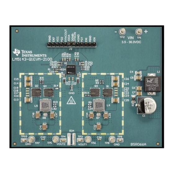
Page 7: Evm Photo
EVM Photo www.ti.com EVM Photo Figure 3. LM5143-Q1 EVM, 100 mm × 75 mm CAUTION Caution Hot surface. Contact may cause burns. Do not touch. SNVU623B – October 2018 – Revised April 2020 LM5143-Q1 EVM User's Guide Submit Documentation Feedback... -
Page 8: Test Setup And Procedure
Channel 1 positive output voltage power and sense connection VOUT2 Channel 2 positive output voltage power and sense connection Negative output voltage power and sense connection LM5143-Q1 EVM User's Guide SNVU623B – October 2018 – Revised April 2020 Submit Documentation Feedback Copyright © 2018–2020, Texas Instruments Incorporated... -
Page 9: Test Equipment
Connect voltmeter 3 at VOUT2 and GND connections to measure the output voltage of channel 2. • Connect ammeter 2 and ammeter 3 to measure the output currents. SNVU623B – October 2018 – Revised April 2020 LM5143-Q1 EVM User's Guide Submit Documentation Feedback Copyright © 2018–2020, Texas Instruments Incorporated... -
Page 10: Test Procedure
The curves with higher efficiency at light load correspond to when diode emulation is enabled (DEMB tied to AGND). Figure 5. Dual-Channel Efficiency, V = 12 V, V = 3.3 V, V = 5 V OUT1 OUT2 LM5143-Q1 EVM User's Guide SNVU623B – October 2018 – Revised April 2020 Submit Documentation Feedback Copyright © 2018–2020, Texas Instruments Incorporated... -
Page 11: Ch1 Efficiency
Figure 7. Ch1 Efficiency, V = 12 V, V = 3.3 V, Diode Emulation, Channel 2 OFF (Log Scale) OUT1 SNVU623B – October 2018 – Revised April 2020 LM5143-Q1 EVM User's Guide Submit Documentation Feedback Copyright © 2018–2020, Texas Instruments Incorporated... - Page 12 Figure 9. Ch2 Efficiency, V = 12 V, V = 5 V, Diode Emulation, Channel 1 OFF (Log Scale) OUT2 LM5143-Q1 EVM User's Guide SNVU623B – October 2018 – Revised April 2020 Submit Documentation Feedback Copyright © 2018–2020, Texas Instruments Incorporated...
- Page 13 = 8V = 12V = 18V Load Current (A) Figure 11. Two-Phase Regulator Efficiency, V = 3.3 V, FPWM SNVU623B – October 2018 – Revised April 2020 LM5143-Q1 EVM User's Guide Submit Documentation Feedback Copyright © 2018–2020, Texas Instruments Incorporated...
-
Page 14: Operating Waveforms
SW2 5V/DIV 80 ns/DIV Figure 13. SW Node Voltages, V = 8 V, I = 7 A OUT1 OUT2 LM5143-Q1 EVM User's Guide SNVU623B – October 2018 – Revised April 2020 Submit Documentation Feedback Copyright © 2018–2020, Texas Instruments Incorporated... - Page 15 Figure 15. Ch1 (3.3 V) Load Transient Response, V = 12 V, FPWM, 3.5 A to 7 A at 1 A/µs SNVU623B – October 2018 – Revised April 2020 LM5143-Q1 EVM User's Guide Submit Documentation Feedback Copyright © 2018–2020, Texas Instruments Incorporated...
- Page 16 Figure 17. Ch2 (5 V) Load Transient Response, V = 12 V, FPWM, 3.5 A to 7 A at 1 A/µs LM5143-Q1 EVM User's Guide SNVU623B – October 2018 – Revised April 2020 Submit Documentation Feedback Copyright © 2018–2020, Texas Instruments Incorporated...
- Page 17 Figure 19. ENABLE ON and OFF, V = 12 V, I = 7 A Resistive, C = 68 nF OUT1 OUT2 SNVU623B – October 2018 – Revised April 2020 LM5143-Q1 EVM User's Guide Submit Documentation Feedback Copyright © 2018–2020, Texas Instruments Incorporated...
- Page 18 VOUT1 1V/DIV IOUT1 2A/DIV 2ms/DIV Figure 21. Shutdown, V = 12 V, I = 7 A Resistive OUT1 OUT2 LM5143-Q1 EVM User's Guide SNVU623B – October 2018 – Revised April 2020 Submit Documentation Feedback Copyright © 2018–2020, Texas Instruments Incorporated...
-
Page 19: Bode Plots
Figure 23. Bode Plot, V = 12 V, V = 5 V, I = 7 A Resistive OUT2 OUT2 SNVU623B – October 2018 – Revised April 2020 LM5143-Q1 EVM User's Guide Submit Documentation Feedback Copyright © 2018–2020, Texas Instruments Incorporated... -
Page 20: Thermal Performance
CISPR 25 EMI Performance Figure 25 presents the EMI performance of the LM5143-Q1 EVM at 13.5-V input and shields installed. Conducted emissions are measured over a frequency range of 150 kHz to 108 MHz using a 5-µH LISN according to the CISPR 25 specification. CISPR 25 class 5 peak and average limit lines are denoted in red. -
Page 21: Evm Documentation
0.22 µF 0.01uF 0.1uF 15pF 1000pF 1000pF CJS-1201TA AGND PGND AGND VOUT2 VOUT1 Net-Tie AGND PGND Figure 26. EVM Schematic SNVU623B – October 2018 – Revised April 2020 LM5143-Q1 EVM User's Guide Submit Documentation Feedback Copyright © 2018–2020, Texas Instruments Incorporated... -
Page 22: Bill Of Materials
Vishay DIP Switch, SPST, 2Pos, Slide, SMT CVS-02TB Copal Electronics Slide SW, SPDT 0.1 A 50VDC CJS-1201TA Copal Electronics LM5143-Q1 EVM User's Guide SNVU623B – October 2018 – Revised April 2020 Submit Documentation Feedback Copyright © 2018–2020, Texas Instruments Incorporated... - Page 23 Keystone TP3, TP4, TP9, TP10 Test Point, Miniature, SMT 5015 Keystone IC, LM5143-Q1, 65-V Dual Synchronous Buck Controller, VQFN-40 LM5143QRGWRQ1 PCB1 PCB, FR4, 6 layer, 2 oz, 100 mm x 75 mm – SNVU623B – October 2018 – Revised April 2020...
-
Page 24: Pcb Layout
Figure 27 through Figure 34 show the design of the LM5143-Q1 EVM using a 6-layer PCB with 2-oz copper thickness. The EVM is essentially a single-sided design except for certain input filtering and small- signal components located on the bottom side. - Page 25 EVM Documentation www.ti.com Figure 29. Layer 3 Copper (Top View) Figure 30. Layer 4 Copper (Top View) SNVU623B – October 2018 – Revised April 2020 LM5143-Q1 EVM User's Guide Submit Documentation Feedback Copyright © 2018–2020, Texas Instruments Incorporated...
- Page 26 EVM Documentation www.ti.com Figure 31. Layer 5 Copper (Top View) Figure 32. Bottom Copper (Top View) LM5143-Q1 EVM User's Guide SNVU623B – October 2018 – Revised April 2020 Submit Documentation Feedback Copyright © 2018–2020, Texas Instruments Incorporated...
-
Page 27: Component Drawings
EVM Documentation www.ti.com Component Drawings Figure 33. Top Component Drawing Figure 34. Bottom Component Drawing SNVU623B – October 2018 – Revised April 2020 LM5143-Q1 EVM User's Guide Submit Documentation Feedback Copyright © 2018–2020, Texas Instruments Incorporated... -
Page 28: Device And Documentation Support
Related Documentation For related documentation see the following: • LM5143-Q1 Data Sheet (SNVSB29) • LM5143-Q1 4-Phase Buck Regulator Design (SNVA870) • Improve High-current DC/DC Regulator Performance for Free with Optimized Power Stage Layout (SNVA803) • Reduce Buck Converter EMI and Voltage Stress by Minimizing Inductive Parasitics (SLYT682) •... - Page 29 • Added SW node voltage waveform........................• Added EMI results ................• Changed input capacitor C2 in schematic and BOM. SNVU623B – October 2018 – Revised April 2020 Revision History Submit Documentation Feedback Copyright © 2018–2020, Texas Instruments Incorporated...
- Page 30 STANDARD TERMS FOR EVALUATION MODULES Delivery: TI delivers TI evaluation boards, kits, or modules, including any accompanying demonstration software, components, and/or documentation which may be provided together or separately (collectively, an “EVM” or “EVMs”) to the User (“User”) in accordance with the terms set forth herein.
- Page 31 www.ti.com Regulatory Notices: 3.1 United States 3.1.1 Notice applicable to EVMs not FCC-Approved: FCC NOTICE: This kit is designed to allow product developers to evaluate electronic components, circuitry, or software associated with the kit to determine whether to incorporate such items in a finished product and software developers to write software applications for use with the end product.
- Page 32 www.ti.com Concernant les EVMs avec antennes détachables Conformément à la réglementation d'Industrie Canada, le présent émetteur radio peut fonctionner avec une antenne d'un type et d'un gain maximal (ou inférieur) approuvé pour l'émetteur par Industrie Canada. Dans le but de réduire les risques de brouillage radioélectrique à...
- Page 33 www.ti.com EVM Use Restrictions and Warnings: 4.1 EVMS ARE NOT FOR USE IN FUNCTIONAL SAFETY AND/OR SAFETY CRITICAL EVALUATIONS, INCLUDING BUT NOT LIMITED TO EVALUATIONS OF LIFE SUPPORT APPLICATIONS. 4.2 User must read and apply the user guide and other available documentation provided by TI regarding the EVM prior to handling or using the EVM, including without limitation any warning or restriction notices.
- Page 34 Notwithstanding the foregoing, any judgment may be enforced in any United States or foreign court, and TI may seek injunctive relief in any United States or foreign court. Mailing Address: Texas Instruments, Post Office Box 655303, Dallas, Texas 75265 Copyright © 2019, Texas Instruments Incorporated...
- Page 35 TI products. TI’s provision of these resources does not expand or otherwise alter TI’s applicable warranties or warranty disclaimers for TI products. Mailing Address: Texas Instruments, Post Office Box 655303, Dallas, Texas 75265 Copyright © 2020, Texas Instruments Incorporated...
Need help?
Do you have a question about the LM5143-Q1 and is the answer not in the manual?
Questions and answers