Advertisement
Quick Links
www.ti.com
EVM User's Guide: IWRL6432AOPEVM, AWRL6432AOPEVM
Low Power 60GHz mm-Wave Sensor Evaluation Module
Description
The xWRL6432AOPEVM is an easy-to-use, low cost
FR4-based evaluation board for the xWRL6432AOP
mmWave sensing device, with standalone operation
and direct connectivity to the DCA1000EVM for raw
ADC capture and signal processing development.
This EVM contains everything required to start
developing software for on-chip hardware accelerator
and low power ARM
®
Cortex
Features
•
Wide field of view antenna, targeted for wall
mount, ceiling and in-cabin sensing applications
•
FR4-based PCB substrate
•
XDS110 JTAG interface with USB connectivity for
code development and debugging
•
Power optimized discrete DCDC power
management design
•
Serial port for onboard QSPI flash programming
•
60-pin, high-density (HD) connectors for raw
analog-to-digital converter (ADC) data
•
On board CAN-FD transceiver
•
On board LIN PHY transceiver for automotive
variant
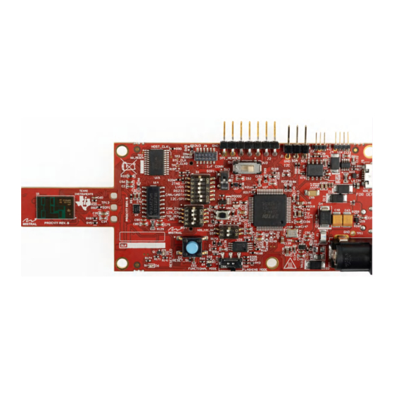
xWRL6432AOPEVM (Top View)
SWRU620 – APRIL 2024
Submit Document Feedback
®
-M4F processor.
Copyright © 2024 Texas Instruments Incorporated
•
On board INA228 for ultra-precise digital power
monitoring
•
USB powered standalone mode of operation
Applications
•
Industrial:
–
Automated door and gate
–
Motion detector
–
Occupancy detection (people tracking, people
counting)
–
Video doorbell
–
IP network camera
–
Air conditioner
–
Refrigerators and freezers
–
Lawn mover
–
Portable electronics
–
Televisions
–
Home theater and entertainment
•
Automotive:
–
Intruder detection
–
One row Life Presence Detection
–
Exterior Intrusion Monitoring / Radar DVR
xWRL6432AOPEVM (Bottom View)
Low Power 60GHz mm-Wave Sensor Evaluation Module
Description
1
Advertisement

Related Manuals for Texas Instruments WRL6432AOPEVM Series


Summary of Contents for Texas Instruments WRL6432AOPEVM Series
- Page 1 • On board CAN-FD transceiver • On board LIN PHY transceiver for automotive variant xWRL6432AOPEVM (Top View) xWRL6432AOPEVM (Bottom View) SWRU620 – APRIL 2024 Low Power 60GHz mm-Wave Sensor Evaluation Module Submit Document Feedback Copyright © 2024 Texas Instruments Incorporated...
-
Page 2: Kit Contents
1 Evaluation Module Overview 1.1 Introduction The xWRL6432AOP Evaluation Module (EVM) offered by Texas Instruments presents an easily navigable and cost-effective platform for assessing the capabilities of the xWRL6432AOP mmWave sensing device. Designed with an FR4-based PCB substrate, this evaluation board has seamless integration with the DCA1000EVM for direct connectivity, facilitating raw ADC capture and signal processing development. - Page 3 Figure 1-2. Muxing Options for the EVM SWRU620 – APRIL 2024 Low Power 60GHz mm-Wave Sensor Evaluation Module Submit Document Feedback Copyright © 2024 Texas Instruments Incorporated...
-
Page 4: Device Information
The xWRL6432AOPEVM includes three receiver and two transmitter short range antennas on the package of chip.Figure 1-3 shows the antenna on package. Figure 1-3. AOP Antennas Low Power 60GHz mm-Wave Sensor Evaluation Module SWRU620 – APRIL 2024 Submit Document Feedback Copyright © 2024 Texas Instruments Incorporated... - Page 5 TX1 and TX2. Both show the radiation pattern for TX1 and TX2 and RX1, RX2 and RX3 together. SWRU620 – APRIL 2024 Low Power 60GHz mm-Wave Sensor Evaluation Module Submit Document Feedback Copyright © 2024 Texas Instruments Incorporated...
- Page 6 Evaluation Module Overview www.ti.com Figure 1-5. Measured Azimuth Radiation Pattern for All Tx to Rx Pairs (All 6 Virtual Antenna Pairs Included) Low Power 60GHz mm-Wave Sensor Evaluation Module SWRU620 – APRIL 2024 Submit Document Feedback Copyright © 2024 Texas Instruments Incorporated...
- Page 7 Evaluation Module Overview Figure 1-6. Measured Elevation Radiation Pattern for All Tx to Rx Pairs (All 6 Virtual Antenna Pairs Included) SWRU620 – APRIL 2024 Low Power 60GHz mm-Wave Sensor Evaluation Module Submit Document Feedback Copyright © 2024 Texas Instruments Incorporated...
- Page 8 Hardware www.ti.com 2 Hardware Figure 2-1. Salient Features of EVM (Top side) Figure 2-2. Salient Features of EVM (Bottom side) Low Power 60GHz mm-Wave Sensor Evaluation Module SWRU620 – APRIL 2024 Submit Document Feedback Copyright © 2024 Texas Instruments Incorporated...
-
Page 9: Switches And Leds
Figure 2-4. S1 Switch OFF : CAN S1.5 CAN/UARTA ON : XDS_UARTA OFF : I2C, REG_MODE, LED_SW_GPIO S1.6 I2C/SPI ON : SPI SWRU620 – APRIL 2024 Low Power 60GHz mm-Wave Sensor Evaluation Module Submit Document Feedback Copyright © 2024 Texas Instruments Incorporated... - Page 10 Flashing Mode (as shown in image) Reference Design Connectivity (Only required when reference design is Switch connected on EVM) Figure 2-10. SW3 Switch Low Power 60GHz mm-Wave Sensor Evaluation Module SWRU620 – APRIL 2024 Submit Document Feedback Copyright © 2024 Texas Instruments Incorporated...
- Page 11 Glows if there is any HW error in the mmWave NERROUT sensor device. Figure 2-15. D9 YELLOW FTDI Glows if the USB is in suspend mode Figure 2-16. D10 SWRU620 – APRIL 2024 Low Power 60GHz mm-Wave Sensor Evaluation Module Submit Document Feedback Copyright © 2024 Texas Instruments Incorporated...
- Page 12 (SPI, UART, I2C, NRST, NERROR, and SOPs) to the DCA1000. Figure 2-17. DCA1000 HD Connector Low Power 60GHz mm-Wave Sensor Evaluation Module SWRU620 – APRIL 2024 Submit Document Feedback Copyright © 2024 Texas Instruments Incorporated...
- Page 13 S1.5 to off position. Figure 2-19. Analog Mux for the CAN PHY Switch Figure 2-20. CAN FD PHY Used in the EVM SWRU620 – APRIL 2024 Low Power 60GHz mm-Wave Sensor Evaluation Module Submit Document Feedback Copyright © 2024 Texas Instruments Incorporated...
- Page 14 Reference Designator Supply Node PCB Net Name 1.8V Supply REG_1V8 3.3V Supply VCC_3V3 1.2V Supply REG_1V2 1.2V RF Supply REG_RF_1V2 Low Power 60GHz mm-Wave Sensor Evaluation Module SWRU620 – APRIL 2024 Submit Document Feedback Copyright © 2024 Texas Instruments Incorporated...
- Page 15 Figure 2-25. EVM in Functional Mode Using Standalone Operation EVM uses single UART port for both device configuration and processed data communication to PC. SWRU620 – APRIL 2024 Low Power 60GHz mm-Wave Sensor Evaluation Module Submit Document Feedback Copyright © 2024 Texas Instruments Incorporated...
-
Page 16: Ftdi Interface
COM port numbers, as shown in .Figure 2-27 Figure 2-27. Installed FTDI Drivers Low Power 60GHz mm-Wave Sensor Evaluation Module SWRU620 – APRIL 2024 Submit Document Feedback Copyright © 2024 Texas Instruments Incorporated... - Page 17 Figure 3-1. Flash Tab in Visualizer Tool Figure 3-2. Out of Box Demo Binary App SWRU620 – APRIL 2024 Low Power 60GHz mm-Wave Sensor Evaluation Module Submit Document Feedback Copyright © 2024 Texas Instruments Incorporated...
- Page 18 Please refer to Out-of-box demo tutorial for xWRL6432AOP evaluation modules. Figure 3-3. Configuration Dashboard Low Power 60GHz mm-Wave Sensor Evaluation Module SWRU620 – APRIL 2024 Submit Document Feedback Copyright © 2024 Texas Instruments Incorporated...
- Page 19 Software Figure 3-4. Plots Tab in Visualizer Tool SWRU620 – APRIL 2024 Low Power 60GHz mm-Wave Sensor Evaluation Module Submit Document Feedback Copyright © 2024 Texas Instruments Incorporated...
- Page 20 Figure 3-6. DCA1000EVM mode (Side View) Please refer to Section 2.2.2 for the switch settings for the DCA1000 raw ADC capture card. Low Power 60GHz mm-Wave Sensor Evaluation Module SWRU620 – APRIL 2024 Submit Document Feedback Copyright © 2024 Texas Instruments Incorporated...
-
Page 21: Additional Information
Search the forums at e2e.ti.com. If users cannot find the answer, then post the question to the community. 8 References DCA1000EVM Data Capture Card User’s Guide MMWAVE-L-SDK SWRU620 – APRIL 2024 Low Power 60GHz mm-Wave Sensor Evaluation Module Submit Document Feedback Copyright © 2024 Texas Instruments Incorporated... - Page 22 STANDARD TERMS FOR EVALUATION MODULES Delivery: TI delivers TI evaluation boards, kits, or modules, including any accompanying demonstration software, components, and/or documentation which may be provided together or separately (collectively, an “EVM” or “EVMs”) to the User (“User”) in accordance with the terms set forth herein.
- Page 23 www.ti.com Regulatory Notices: 3.1 United States 3.1.1 Notice applicable to EVMs not FCC-Approved: FCC NOTICE: This kit is designed to allow product developers to evaluate electronic components, circuitry, or software associated with the kit to determine whether to incorporate such items in a finished product and software developers to write software applications for use with the end product.
- Page 24 www.ti.com Concernant les EVMs avec antennes détachables Conformément à la réglementation d'Industrie Canada, le présent émetteur radio peut fonctionner avec une antenne d'un type et d'un gain maximal (ou inférieur) approuvé pour l'émetteur par Industrie Canada. Dans le but de réduire les risques de brouillage radioélectrique à...
- Page 25 www.ti.com EVM Use Restrictions and Warnings: 4.1 EVMS ARE NOT FOR USE IN FUNCTIONAL SAFETY AND/OR SAFETY CRITICAL EVALUATIONS, INCLUDING BUT NOT LIMITED TO EVALUATIONS OF LIFE SUPPORT APPLICATIONS. 4.2 User must read and apply the user guide and other available documentation provided by TI regarding the EVM prior to handling or using the EVM, including without limitation any warning or restriction notices.
- Page 26 Notwithstanding the foregoing, any judgment may be enforced in any United States or foreign court, and TI may seek injunctive relief in any United States or foreign court. Mailing Address: Texas Instruments, Post Office Box 655303, Dallas, Texas 75265 Copyright © 2023, Texas Instruments Incorporated...
- Page 27 TI products. TI’s provision of these resources does not expand or otherwise alter TI’s applicable warranties or warranty disclaimers for TI products. TI objects to and rejects any additional or different terms you may have proposed. IMPORTANT NOTICE Mailing Address: Texas Instruments, Post Office Box 655303, Dallas, Texas 75265 Copyright © 2024, Texas Instruments Incorporated...
Need help?
Do you have a question about the WRL6432AOPEVM Series and is the answer not in the manual?
Questions and answers