Table of Contents
Advertisement
Quick Links
This user's guide describes the characteristics, operation, and use of the INA290 evaluation module
(EVM). This EVM is designed to evaluate the performance of the INA290 voltage-output, current shunt
monitor in a variety of configurations. Throughout this document, the terms evaluation board, evaluation
module, and EVM are synonymous with the INA290EVM. This document also includes a schematic,
reference printed-circuit board (PCB) layouts, and a complete bill of materials (BOM).
SBOU230 – October 2019
Submit Documentation Feedback
Copyright © 2019, Texas Instruments Incorporated
User's Guide
SBOU230 – October 2019
INA290EVM
1
INA290EVM
Advertisement
Table of Contents

Related Manuals for Texas Instruments INA290EVM


Summary of Contents for Texas Instruments INA290EVM
- Page 1 Throughout this document, the terms evaluation board, evaluation module, and EVM are synonymous with the INA290EVM. This document also includes a schematic, reference printed-circuit board (PCB) layouts, and a complete bill of materials (BOM).
-
Page 2: Table Of Contents
Contents ...... General Texas Instruments High Voltage Evaluation (TI HV EVM) User Safety Guidelines ........................Overview ....................EVM Kit Contents .............. Related Documentation From Texas Instruments ........................Hardware ......................Features ........................Operation ....................Quick Start Setup ...................... Measurements ...................... -
Page 3: General Texas Instruments High Voltage Evaluation (Ti Hv Evm) User Safety Guidelines
Any other use and/or application are strictly prohibited by Texas Instruments. If you are not suitable qualified, you should immediately stop from further use of the HV EVM. - Page 4 General Texas Instruments High Voltage Evaluation (TI HV EVM) User Safety Guidelines www.ti.com 3. Personal Safety a. Wear personal protective equipment (for example, latex gloves or safety glasses with side shields) or protect EVM in an adequate lucent plastic box with interlocks to protect from accidental touch.
-
Page 5: Overview
Item Item Part Number Quantity INA290EVM test board INA290EVM Related Documentation From Texas Instruments This document provides information regarding Texas Instruments' integrated circuits used in the assembly of the INA290EVM. Table 3. Related Documentation Document Literature Number INA290-Q1 product data sheet SBOS955 SBOU230 –... -
Page 6: Hardware
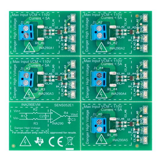
(EMC) testing. The INA290EVM is one PCB with five optional PCB cutouts the engineer can use to test each of the five gain options (1 to 5) listed in Table 1. -
Page 7: Operation
Operation Quick Start Setup Follow these procedures to set up and use one of the INA290EVM panels. For these instructions, n is gain option 1, 2, 3, 4, or 5. Step 1. Choose the desired gain option panel variation. -
Page 8: Evm Components
EVM Components www.ti.com EVM Components This section summarizes the INA290EVM components. For these instructions, n is gain option 1, 2, 3, 4, or 5. R2_An, R3_An, R4_An, C2_An, C3_An R2_An, R3_An, R4_An, are factory-installed 0-Ω 0603 resistors. C2_An, C3_An, are not populated. -
Page 9: Schematic, Pcb Layout, And Bill Of Materials
INA290EVM PCB manufacturing. Schematics Figure 1 through Figure 5 show the schematics for the A pinout of the INA290EVM PCB for all gain options. Figure 1. INA290EVM Schematic: Gain A1 Panel SBOU230 – October 2019 INA290EVM Submit Documentation Feedback Copyright © 2019, Texas Instruments Incorporated... -
Page 10: Ina290Evm Schematic: Gain A2 Panel
Schematic, PCB Layout, and Bill of Materials www.ti.com Figure 2. INA290EVM Schematic: Gain A2 Panel INA290EVM SBOU230 – October 2019 Submit Documentation Feedback Copyright © 2019, Texas Instruments Incorporated... -
Page 11: Ina290Evm Schematic: Gain A3 Panel
Schematic, PCB Layout, and Bill of Materials www.ti.com Figure 3. INA290EVM Schematic: Gain A3 Panel SBOU230 – October 2019 INA290EVM Submit Documentation Feedback Copyright © 2019, Texas Instruments Incorporated... -
Page 12: Ina290Evm Schematic: Gain A4 Panel
Schematic, PCB Layout, and Bill of Materials www.ti.com Figure 4. INA290EVM Schematic: Gain A4 Panel INA290EVM SBOU230 – October 2019 Submit Documentation Feedback Copyright © 2019, Texas Instruments Incorporated... -
Page 13: Ina290Evm Schematic: Gain A5 Panel
Schematic, PCB Layout, and Bill of Materials www.ti.com Figure 5. INA290EVM Schematic: Gain A5 Panel SBOU230 – October 2019 INA290EVM Submit Documentation Feedback Copyright © 2019, Texas Instruments Incorporated... -
Page 14: Pcb Layout
Schematic, PCB Layout, and Bill of Materials www.ti.com PCB Layout Figure 6 through Figure 12 show the PCB layout for the INA290EVM. Figure 6. INA290EVM Top Overlay Figure 7. INA290EVM Bottom Overlay Figure 8. INA290EVM Top Layer Figure 9. INA290EVM Bottom Layer INA290EVM SBOU230 –... -
Page 15: Ina290Evm Drill Drawing
Schematic, PCB Layout, and Bill of Materials www.ti.com Figure 10. INA290EVM Top Solder Figure 11. INA290EVM Bottom Solder Figure 12. INA290EVM Drill Drawing SBOU230 – October 2019 INA290EVM Submit Documentation Feedback Copyright © 2019, Texas Instruments Incorporated... -
Page 16: Bill Of Materials
Schematic, PCB Layout, and Bill of Materials www.ti.com Bill of Materials Table 4 provides the parts list for the INA290EVM. Table 4. Bill of Materials Designator Value Description Package Reference Part Number Manufacturer C1_A1, C1_A2, C1_A3, C1_A4, 0.1uF CAP, CERM, 0.1 uF, 25 V, +/- 10%, X7R, AEC-Q200 Grade 1,... - Page 17 STANDARD TERMS FOR EVALUATION MODULES Delivery: TI delivers TI evaluation boards, kits, or modules, including any accompanying demonstration software, components, and/or documentation which may be provided together or separately (collectively, an “EVM” or “EVMs”) to the User (“User”) in accordance with the terms set forth herein.
- Page 18 www.ti.com Regulatory Notices: 3.1 United States 3.1.1 Notice applicable to EVMs not FCC-Approved: FCC NOTICE: This kit is designed to allow product developers to evaluate electronic components, circuitry, or software associated with the kit to determine whether to incorporate such items in a finished product and software developers to write software applications for use with the end product.
- Page 19 www.ti.com Concernant les EVMs avec antennes détachables Conformément à la réglementation d'Industrie Canada, le présent émetteur radio peut fonctionner avec une antenne d'un type et d'un gain maximal (ou inférieur) approuvé pour l'émetteur par Industrie Canada. Dans le but de réduire les risques de brouillage radioélectrique à...
- Page 20 www.ti.com EVM Use Restrictions and Warnings: 4.1 EVMS ARE NOT FOR USE IN FUNCTIONAL SAFETY AND/OR SAFETY CRITICAL EVALUATIONS, INCLUDING BUT NOT LIMITED TO EVALUATIONS OF LIFE SUPPORT APPLICATIONS. 4.2 User must read and apply the user guide and other available documentation provided by TI regarding the EVM prior to handling or using the EVM, including without limitation any warning or restriction notices.
- Page 21 Notwithstanding the foregoing, any judgment may be enforced in any United States or foreign court, and TI may seek injunctive relief in any United States or foreign court. Mailing Address: Texas Instruments, Post Office Box 655303, Dallas, Texas 75265 Copyright © 2019, Texas Instruments Incorporated...
- Page 22 TI products. TI’s provision of these resources does not expand or otherwise alter TI’s applicable warranties or warranty disclaimers for TI products. Mailing Address: Texas Instruments, Post Office Box 655303, Dallas, Texas 75265 Copyright © 2019, Texas Instruments Incorporated...
Need help?
Do you have a question about the INA290EVM and is the answer not in the manual?
Questions and answers