Table of Contents
Advertisement
Quick Links
www.ti.com
User's Guide
AWR2544LOP Evaluation Module
Started........................................................................................................................................................................2
1.1 Introduction........................................................................................................................................................................
.....................................................................................................................................................................2
Included..................................................................................................................................................................2
2 Hardware.................................................................................................................................................................................
Diagram....................................................................................................................................................................6
Recommendations......................................................................................................................................6
2.3 Power Connections............................................................................................................................................................
2.4
Connectors.........................................................................................................................................................................7
2.5
Antenna............................................................................................................................................................................16
2.6 PMIC................................................................................................................................................................................
2.7 On-Board Sensors...........................................................................................................................................................
2.8 PC Connection.................................................................................................................................................................
2.9 Connecting the AWR2544LOPEVM to the DCA1000 EVM.............................................................................................
2.10 Jumpers, Switches, and LEDs.......................................................................................................................................
3.1 Design Files.....................................................................................................................................................................
4 Revision History...................................................................................................................................................................
Trademarks
ARM
®
and Cortex
®
are registered trademarks of Arm Limited.
Windows
®
is a registered trademark of Microsoft.
All trademarks are the property of their respective owners.
SPRUJB0 - NOVEMBER 2023
Submit Document Feedback
Table of Contents
Tools.........................................................................................................................................29
Code..........................................................................................................29
Copyright © 2023 Texas Instruments Incorporated
Table of Contents
AWR2544LOP Evaluation Module
2
3
7
18
19
19
21
24
29
29
1
Advertisement
Table of Contents

Related Manuals for Texas Instruments AWR2544LOP


Summary of Contents for Texas Instruments AWR2544LOP
-
Page 1: Table Of Contents
® are registered trademarks of Arm Limited. Windows ® is a registered trademark of Microsoft. All trademarks are the property of their respective owners. SPRUJB0 – NOVEMBER 2023 AWR2544LOP Evaluation Module Submit Document Feedback Copyright © 2023 Texas Instruments Incorporated... -
Page 2: Getting Started
The following power supply has been tested to work with the AWR2544LOPEVM: SDI65-12-U-P5. 1.3.2 mmWave Out-of-Box (OOB) Demo TI provides sample demo codes to easily get started with the AWR2544LOP evaluation module (EVM) and to experience the functionality of the AWR2544LOP radar sensor. For details on getting started with these demos, see www.ti.com/tool/mmwave-sdk. -
Page 3: Hardware
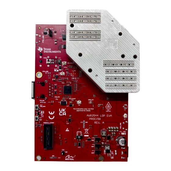
Hardware 2 Hardware Note During operation, a minimum separation distance of 20 centimeters must be maintained between the user and the EVM. SPRUJB0 – NOVEMBER 2023 AWR2544LOP Evaluation Module Submit Document Feedback Copyright © 2023 Texas Instruments Incorporated... - Page 4 Hardware www.ti.com Figure 2-1. AWR2544LOPEVM Front View AWR2544LOP Evaluation Module SPRUJB0 – NOVEMBER 2023 Submit Document Feedback Copyright © 2023 Texas Instruments Incorporated...
- Page 5 Hardware Figure 2-2. AWR2544LOPEVM Back View SPRUJB0 – NOVEMBER 2023 AWR2544LOP Evaluation Module Submit Document Feedback Copyright © 2023 Texas Instruments Incorporated...
-
Page 6: Block Diagram
EVM in the supplied ESD bag when not in use. Handle using an antistatic wristband. Operate on an antistatic work surface. For more information on proper handling, refer to SSYA010A. AWR2544LOP Evaluation Module SPRUJB0 – NOVEMBER 2023 Submit Document Feedback Copyright © 2023 Texas Instruments Incorporated... -
Page 7: Power Connections
To use this interface, the JTAG lines from the AWR2544LOPEVM needs to be muxed to MIPI 60-pin connector. Refer to Section 2.8.1 for more details. SPRUJB0 – NOVEMBER 2023 AWR2544LOP Evaluation Module Submit Document Feedback Copyright © 2023 Texas Instruments Incorporated... - Page 8 Pin Number Description MIPI_VREF_DEBUG MIPI_TMS MIPI_TCK MIPI_TDO MIPI_TDI MIPI_NRST MIPI_RTCK MIPI_TRSTPD MIPI_JTAG_NRST MIPI_VREF_DEBUG TRACE_CLK MIPI_DBG_DETECT TRACE_CTL TRACE_DATA0 TRACE_DATA1 TRACE_DATA2 TRACE_DATA3 TRACE_DATA4 TRACE_DATA5 TRACE_DATA6 TRACE_DATA7 AWR2544LOP Evaluation Module SPRUJB0 – NOVEMBER 2023 Submit Document Feedback Copyright © 2023 Texas Instruments Incorporated...
- Page 9 2.8.1. The debug connector supports direct connection to the TMDS273GPEVM for CSI2 data processing. For more details refer to CSI2 FE Connector ECO List. SPRUJB0 – NOVEMBER 2023 AWR2544LOP Evaluation Module Submit Document Feedback Copyright © 2023 Texas Instruments Incorporated...
- Page 10 Hardware www.ti.com Figure 2-6. 60-pin Debug Connector AWR2544LOP Evaluation Module SPRUJB0 – NOVEMBER 2023 Submit Document Feedback Copyright © 2023 Texas Instruments Incorporated...
- Page 11 1. Populate R51 2. Populate R135 3. Remove R351 and populate on R138 4. Remove R361 and populate on R160 5. Populate R164 6. Populate R167 SPRUJB0 – NOVEMBER 2023 AWR2544LOP Evaluation Module Submit Document Feedback Copyright © 2023 Texas Instruments Incorporated...
- Page 12 ETH_D1N LED_ACTn LED_LINKn ETH_GND ETH_GND Figure 2-7. RJ45 Connector Figure 2-8 shows the Ethernet MATEnet connector, and Table 2-4 provides the connector pin details. AWR2544LOP Evaluation Module SPRUJB0 – NOVEMBER 2023 Submit Document Feedback Copyright © 2023 Texas Instruments Incorporated...
- Page 13 The automotive Ethernet PHY (U4) and port (J4) on the AWR2544LOPEVM have not been tested by Texas Instruments to be compliant with any regional standards such as Radio Equipment Directive 2014/53/EU. If the user wishes to populate the components necessary to utilize this port, it is up to the user to do any necessary testing to ensure that the port is compliant with all applicable regional standards before use.
- Page 14 This is the UART interface used to flash the binary to the onboard serial flash and for Out-of-box (OOB) demo. Note The OOB demo requires only J8 to be connected to the PC. J10 is not used for the OOB demo. AWR2544LOP Evaluation Module SPRUJB0 – NOVEMBER 2023 Submit Document Feedback Copyright © 2023 Texas Instruments Incorporated...
- Page 15 Figure 2-10. XDS USB Port 2.4.5 OSC_CLK_OUT Connector (J2) Connector J2 provides access to measure oscillator clock out signal from the AWR2544 device. Figure 2-11. OSC_CLK_OUT Port SPRUJB0 – NOVEMBER 2023 AWR2544LOP Evaluation Module Submit Document Feedback Copyright © 2023 Texas Instruments Incorporated...
-
Page 16: Antenna
This antenna design enables estimation of both azimuth and elevation angles, which enable object detection in a 3-D plane (see Figure 2-13). AWR2544LOP Evaluation Module SPRUJB0 – NOVEMBER 2023 Submit Document Feedback Copyright © 2023 Texas Instruments Incorporated... - Page 17 2-16). Similarly, the horizontal 6 dB beamwidth is approximately ±30 degrees (see Figure 2-15) and the elevation 6dB-beamwidth is approximately ±5.5 degrees (see Figure 2-16). SPRUJB0 – NOVEMBER 2023 AWR2544LOP Evaluation Module Submit Document Feedback Copyright © 2023 Texas Instruments Incorporated...
-
Page 18: Pmic
Power to the AWR2544 is provided by the LP87725-Q1 PMIC. This is a functional safety compliant PMIC that supports ASIL-B/SIL-2 applications. For more details, visit the LP87725-Q1 product page (https://www.ti.com/ product/LP87725-Q1). AWR2544LOP Evaluation Module SPRUJB0 – NOVEMBER 2023 Submit Document Feedback Copyright © 2023 Texas Instruments Incorporated... -
Page 19: On-Board Sensors
Ports (COM & LPT). Figure 2-17. XDS110 COM Ports XDS110 debug probe and data port are detected under Texas Instruments Debug Probes. Figure 2-18. TI Debug Probes If the PC is unable to recognize the above COM ports, install the latest EMUpack. - Page 20 COM ports are installed, the device manager recognizes these devices and indicates the COM port numbers, as shown in Figure 2-20. Figure 2-20. Installed FTDI Drivers AWR2544LOP Evaluation Module SPRUJB0 – NOVEMBER 2023 Submit Document Feedback Copyright © 2023 Texas Instruments Incorporated...
-
Page 21: Connecting The Awr2544Lopevm To The Dca1000 Evm
Figure 2-21. AWR2544LOPEVM and DCA1000 EVM When using the AWR2544LOPEVM with the DCA1000 EVM, the following settings must be used. 1. Set the AWR2544LOPEVM to SOP2 mode. SPRUJB0 – NOVEMBER 2023 AWR2544LOP Evaluation Module Submit Document Feedback Copyright © 2023 Texas Instruments Incorporated... - Page 22 Hardware www.ti.com Figure 2-22. SOP2 Mode AWR2544LOP Evaluation Module SPRUJB0 – NOVEMBER 2023 Submit Document Feedback Copyright © 2023 Texas Instruments Incorporated...
- Page 23 Hardware 2. Set the AWR2544LOPEVM switch S2 to FTDI_SPI Mode Figure 2-23. FTDI_SPI Mode SPRUJB0 – NOVEMBER 2023 AWR2544LOP Evaluation Module Submit Document Feedback Copyright © 2023 Texas Instruments Incorporated...
-
Page 24: Jumpers, Switches, And Leds
MSS_SPIB interface is routed to the debug connector (J7). When set to ‘FTDI_SPI’, the MSS_SPIB interface is routed to the FTDI USB port (J10) AWR2544LOP Evaluation Module SPRUJB0 – NOVEMBER 2023 Submit Document Feedback Copyright © 2023 Texas Instruments Incorporated... - Page 25 010 (SOP mode 1) = Reserved Figure 2-25. SOP Jumpers Additionally, the SOP[4:3] signals defines the XTAL clock input as per the below configurations provided in Table 2-10. SPRUJB0 – NOVEMBER 2023 AWR2544LOP Evaluation Module Submit Document Feedback Copyright © 2023 Texas Instruments Incorporated...
- Page 26 RESET This Switch is used to RESET the AWR2544, PMIC, XDS110 and FTDI device. GPIO_28 When pushed, the GPIO_28 shall be pulled to High. AWR2544LOP Evaluation Module SPRUJB0 – NOVEMBER 2023 Submit Document Feedback Copyright © 2023 Texas Instruments Incorporated...
- Page 27 Glows if there is any HW error in the AWR2544 device Yellow WRMRST Open drain fail safe warm reset signal Green GPIO_2 Glows when the GPIO_2 is logic-1 SPRUJB0 – NOVEMBER 2023 AWR2544LOP Evaluation Module Submit Document Feedback Copyright © 2023 Texas Instruments Incorporated...
- Page 28 Hardware www.ti.com Table 2-13. On Board LEDs (continued) Color Usage Comments Image Yellow FTDI_SUSPEND_N Glows when FTDI is in suspend state AWR2544LOP Evaluation Module SPRUJB0 – NOVEMBER 2023 Submit Document Feedback Copyright © 2023 Texas Instruments Incorporated...
-
Page 29: Design Files And Software Tools
4 Revision History NOTE: Page numbers for previous revisions may differ from page numbers in the current version. DATE REVISION NOTES November 2023 Initial Release SPRUJB0 – NOVEMBER 2023 AWR2544LOP Evaluation Module Submit Document Feedback Copyright © 2023 Texas Instruments Incorporated... - Page 30 TI products. TI’s provision of these resources does not expand or otherwise alter TI’s applicable warranties or warranty disclaimers for TI products. TI objects to and rejects any additional or different terms you may have proposed. IMPORTANT NOTICE Mailing Address: Texas Instruments, Post Office Box 655303, Dallas, Texas 75265 Copyright © 2023, Texas Instruments Incorporated...
Need help?
Do you have a question about the AWR2544LOP and is the answer not in the manual?
Questions and answers