Table of Contents
Advertisement
Quick Links
Advertisement
Table of Contents

Related Manuals for Supermicro X11DPT-B


Summary of Contents for Supermicro X11DPT-B
- Page 1 X11DPT-B USER’S MANUAL Revision 1.1c...
- Page 2 State of California, USA. The State of California, County of Santa Clara shall be the exclusive venue for the resolution of any such disputes. Supermicro's total liability for all claims will not exceed the price paid for the hardware product.
- Page 3 It also supports up to 9 TB memory with DCPMM** modules (See Note 3 below). The X11DPT-B includes two slots for riser card support, eight SATA 3.0 ports, one SATADOM slot, and two USB 3.0 ports. The X11DPT-B provides maximum performance, system cooling, PCIe capacity, and I/O flexibility.
- Page 4 Table of Contents Appendix A provides UEFI BIOS Error Beep Codes. Appendix B lists software program installation instructions. Appendix C lists standardized warning statements in various languages. Appendix D contains UEFI BIOS Recovery instructions. Appendix E provides information on how to configure VROC RAID settings. Appendix F provides information on how to configure secure boot settings.
- Page 5 Super X11DPT-B User's Manual Contacting Supermicro Headquarters Address: Super Micro Computer, Inc. 980 Rock Ave. San Jose, CA 95131 U.S.A. Tel: +1 (408) 503-8000 Fax: +1 (408) 503-8008 Email: marketing@supermicro.com (General Information) support@supermicro.com (Technical Support) Website: www.supermicro.com Europe Address: Super Micro Computer B.V.
-
Page 6: Table Of Contents
Table of Contents Table of Contents Chapter 1 Introduction 1.1 Overview ..........................8 1.2 Processor and Chipset Overview ..................17 1.3 Special Features ........................18 1.4 System Health Monitoring ....................18 1.5 ACPI Features ........................19 1.6 Power Supply ........................19 1.7 Advanced Power Management ..................19 1.8 Intel®... - Page 7 Super X11DPT-B User's Manual 4.5 IPMI ..........................119 4.6 Security Settings ......................122 4.7 Boot Settings ........................126 4.8 Save & Exit ........................129 Appendix A UEFI BIOS Codes Appendix B Software Installation B.1 Microsoft Windows OS Installation ...................132 B.2 Driver Installation ......................134 B.3 SuperDoctor 5 .........................135...
-
Page 8: Chapter 1 Introduction
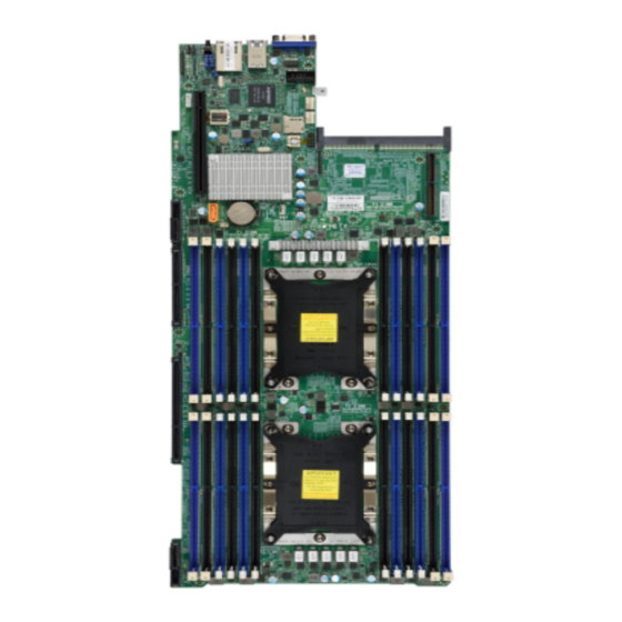
1.1 Overview Congratulations on purchasing your computer motherboard from an industry leader. Supermicro motherboards are designed to provide you with the highest standards in quality and performance. Note: This motherboard was designed to be a part of an integrated server solution. - Page 9 Chapter 1: Introduction X11DPT-B Motherboard Image Note: All graphics shown in this manual were based upon the latest PCB revision available at the time of publication of the manual. The motherboard you received may or may not look exactly the same as the graphics shown in this manual.
- Page 10 Super X11DPT-B User's Manual X11DPT-B Motherboard Layout (not drawn to scale) JPB1 JPG1 USB0/1(3.0) COM1 IPMI_LAN FAN3 FLASH BMC_HB_LED1 FAN4 JSDCARD1 JTPM1 JSIOM1 SIOM:CPU1 PCI-E 3.0 X16 JCPLD1 HDD_LED1 BIOS LICENSE X11DPT-B DESIGNED IN USA IPMI CODE JSD1 REV:1.02 JSD1: SATA DOM POWER...
- Page 11 FAN4 JSDCARD1 JTPM1 JTPM1 JSIOM1 SIOM:CPU1 PCI-E 3.0 X16 JCPLD1 JNVI2C1 JCPLD1 HDD_LED1 HDD_LED1 BIOS LICENSE SXB4 I-SATA6 X11DPT-B JBT1 DESIGNED IN USA IPMI CODE JSD1 JSD1 REV:1.02 JSD1: SATA DOM POWER CPU1 SXB1 SXB2 CPU2 Notes: • See Chapter 2 for detailed information on jumpers, I/O ports, and JF1 front panel con- nections.
- Page 12 90-day trial period. After the trial period, the RAID 0 will be deleted, which could result in data loss. In order to create an NVMe RAID, you must have a VROC key installed on the platform. To purchase a correct VROC key from Supermicro, please refer to follow- ing part numbers (AOC-VROCINTMOD, AOC-VROCSTNMOD, AOC-VROCPREMOD).
- Page 13 DIMM Size • Up to 256 GB at 1.2V Note 1: Memory speed support depends on the processors used in the system. Note 2: For the latest CPU/memory updates, please refer to our website at http://www.supermicro.com/products/ motherboard. Chipset • Intel C621 Chipset Expansion Slots •...
- Page 14 • Power-on mode for AC power recovery • Intel® Intelligent Power Node Manager 3.0 (available when the Supermicro Power Manager [SPM] is installed and a special power supply is used. See the note on page 20.) • Management Engine (ME) System Health Monitoring •...
- Page 15 User's Guide available at http://www.supermicro.com/support/manuals/. Note 3: It is strongly recommended that you change BMC login information upon initial system power-on. The manufacturer default username is ADMIN and the password is ADMIN. For proper BMC configuration, please refer to http://www.supermicro.com.
- Page 16 Super X11DPT-B User's Manual System Block Diagram VCCP0 12v VCCP1 12v VR13 VR13 DIMMA1/2 DIMMG1/2 DIMMB1/2 DIMMH1/2 5+1 PHASE 5+1 PHASE DIMMC1/2 DIMMJ1/2 205W 205W 10.4/11.2G DIMMK1/2 DIMMD1/2 CPU#1 CPU#2 DIMML1/2 DIMME1/2 DIMMM1/2 DIMMF1/2 IMC0 3CH IMC1 3CH PECI : 30...
-
Page 17: Processor And Chipset Overview
Chapter 1: Introduction 1.2 Processor and Chipset Overview Built upon the functionality and capability of Intel Xeon Scalable-SP and 2nd Generation Intel Xeon Scalable-SP processors (Socket P) with support of Intel C621 chipset, this motherboard provides superb system performance, efficient power management, and a rich feature set based on cutting-edge technologies to address the needs of next-generation users. -
Page 18: Special Features
Super X11DPT-B User's Manual 1.3 Special Features This section describes the health monitoring features of the X11DPT-B motherboard. The motherboard has an onboard ASPEED AST 2500 Baseboard Management Controller (BMC) that supports system health monitoring. Recovery from AC Power Loss The Basic I/O System (UEFI BIOS) provides a setting that determines how the system will respond when AC power is lost and then restored to the system. -
Page 19: Acpi Features
Windows operating systems. For detailed information on OS support, please refer to our website at www.supermicro.com. 1.6 Power Supply As with all computer products, a stable power source is necessary for proper and reliable operation. -
Page 20: Intel® Optane Dc Persistent Memory Overview
Super X11DPT-B User's Manual 1.8 Intel® Optane DC Persistent Memory Overview 2nd Generation Intel Xeon Scalable-SP processors support new DCPMM (Optane™ DC Persistent Memory Modules) technology that offers data persistence with higher capacity than existing memory modules and lower latency than NVMe SSDs. DCPMM memory provides hyper-speed storage capability for high performance computing platforms with flexible configuration options. -
Page 21: Chapter 2 Installation
Chapter 2: Installation Chapter 2 Installation 2.1 Static-Sensitive Devices Electrostatic Discharge (ESD) can damage electronic com ponents. To avoid damaging your motherboard and your system, it is important to handle it very carefully. The following measures are generally sufficient to protect your equipment from ESD. Precautions •... -
Page 22: Installing The Motherboard
Super X11DPT-B User's Manual 2.2 Installing the Motherboard All motherboards have standard mounting holes to fit different types of chassis. Make sure that the locations of all the mounting holes for both the motherboard and the chassis match. Although a chassis may have both plastic and metal mounting fasteners, metal ones are highly recommended because they ground the motherboard to the chassis. - Page 23 Chapter 2: Installation Installing the Motherboard 1. Install the I/O shield into the back of the chassis as needed. 2. Locate the mounting holes on the motherboard. See the previous page for the location. 3. Locate the matching mounting holes on the chassis. Align the mounting holes on the motherboard against the mounting holes on the chassis.
-
Page 24: Processor And Heatsink Installation
CPU socket cap is in place and none of the socket pins are bent; otherwise, contact your retailer immediately. • Refer to the Supermicro website for updates on CPU support. Intel Xeon Scalable-SP and 2nd Gen Intel Xeon Scalable-SP Processors Intel Xeon Scalable-SP and 2nd Gen Intel Xeon Scalable-SP Processor Note: All graphics, drawings and pictures shown in this manual are for illustration only. - Page 25 Chapter 2: Installation Overview of the Processor Socket Assembly The processor socket assembly contains 1) Intel Xeon Scalable-SP or 2nd Generation Intel Xeon Scalable-SP processor, 2) CPU/heatsink carrier, 3) dust cover, and 4) CPU socket. 1. Intel Processor 2. CPU/Heatsink Carrier 3.
- Page 26 Super X11DPT-B User's Manual Overview of the Processor Heatsink Module The processor heatsink module (PHM) contains 1) a passive heatsink, 2) a CPU/heatsink carrier, and 3) Intel Xeon Scalable-SP or 2nd Generation Intel Xeon Scalable-SP processor. 1. Passive Heatsink 2. CPU/Heatsink Carrier 3.
- Page 27 Chapter 2: Installation Preparing the CPU Socket for Installation This motherboard comes with the CPU socket pre-assembled in the factory. The CPU socket contains 1) a dust cover, 2) a socket bracket, 3) the CPU socket, and 4) a back plate. These components are pre-installed on the motherboard before shipping.
- Page 28 Super X11DPT-B User's Manual Attaching the Processor to the CPU/Heatsink Carrier To properly install the CPU onto the CPU/heatsink carrier, please follow the steps below. 1. Locate Pin 1 (Notch A), Notch B, and Notch C on the CPU and locate Pin 1 (Notch A), Notch B, and Notch C on the CPU/heatsink carrier.
- Page 29 Chapter 2: Installation Attaching the Processor Package Assembly to the Heatsink to Form the Processor Heatsink Module (PHM) After you have made a processor package assembly by following the instructions on the previous page, please follow the steps below to mount the processor package assembly onto the heatsink to create the Processor Heatsink Module (PHM).
- Page 30 Super X11DPT-B User's Manual Installing the Processor Heatsink Module (PHM) 1. Once you have assembled the processor heatsink module (PHM) by following the instructions listed on the previous page, align the processor heatsink module with the CPU socket on the motherboard.
- Page 31 Chapter 2: Installation Removing the Processor Heatsink Module (PHM) Before starting to remove the processor heatsink module (PHM), unplug power cord from the power outlet. 1. Using a T30-size star driver, turn the screws on the PHM counterclockwise to loosen it from the socket, starting with screw marked #4 (in the sequence of 4, 3, 2, 1).
-
Page 32: Memory Support And Installation
Super X11DPT-B User's Manual 2.4 Memory Support and Installation Note: Check Supermicro's website for recommended memory modules. Exercise ex- treme care when installing or removing DIMM modules to prevent any damage. Memory Support This motherboard supports up to 6TB of 3DS Load Reduced DIMM (3DS LRDIMM), Load... - Page 33 Chapter 2: Installation DDR4 Memory Support for the Intel Xeon Scalable-SP Processors DDR4 Memory Support Speed (MT/s); Voltage (V); Slots Per Channel (SPC) and DIMMs Per Channel (DPC) DIMM Capacity (GB) Ranks Per 1 Slot Per Channel 2 Slots Per Channel Type DIMM &...
- Page 34 LRDIMM 3Ds 8Rx4 4H-128GB 4H-256GB 2933 2933 2933 Note 1. 2933 MHz memory support in two-DIMMs per-channel (2DPC) configuration can be achieved by using memory purchased from Supermicro. Note 2. Support for 2933 MHz memory is dependent on the CPU SKU.
- Page 35 Chapter 2: Installation DIMM Population Guidelines for Optimal Performance For optimal memory performance, follow the instructions listed in the tables below when populating memory modules. Key Parameters for DIMM Configuration Key Parameters for DIMM Configurations Parameters Possible Values Number of Channels 1, 2, 3, 4, 5, or 6 Number of DIMMs per 1DPC (1 DIMM Per Channel) or 2DPC (2 DIMMs Per Channel)
- Page 36 Super X11DPT-B User's Manual DIMM Population Table Note: Unbalanced memory configuration decreases memory performance and is not recommended for Supermicro motherboards. Memory Population based on Intel Xeon Scalable-SP and 2nd Gen Intel Xeon Scalable-SP Processors Memory Population Table for the X11DP Motherboard w/24 DIMM Slots Onboard...
- Page 37 Chapter 2: Installation Memory Rank Sparing Tables Dual Rank Memory Rank Sparing (16GB DIMM) Memory Population Total RAM Detected One Rank Configuration Two Rank Configuration A1+B1 16GB 16GB A1+B1+C1 24GB 24GB A1+B1+C1+D1 32GB 32GB A1+B1+C1+D1+E1 40GB 40GB A1+B1+C1+D1+E1+F1 49GB 49GB A1+A2 24GB 16GB...
- Page 38 Super X11DPT-B User's Manual DCPMM Population Tables based on the 2nd Gen Intel Xeon Scalable-SP Processors Note: Only 2nd Gen Intel Xeon Scalable-SP (82xx/62xx/52xx/4215 series) processors support DCPMM memory. Symmetric Population within 1 CPU Socket Channel Modes P1-DIMMF1 P1-DIMMF2 P1-DIMME1...
- Page 39 Chapter 2: Installation Validation Matrix (DDR4 DIMMs Validated w/DCPMM) DIMM Capacity (GB) Ranks Per DIMM DIMM Type & Data Width DRAM Density (Stack) 1Rx4 16GB 2Rx8 16GB RDIMM 2Rx4 16GB 32GB LRDIMM 4Rx4 64GB LRDIMM 3DS 8Rx4 (4H) 128GB...
- Page 40 Super X11DPT-B User's Manual DIMM Installation JPB1 JPG1 USB0/1(3.0) COM1 IPMI_LAN Please follow the instructions given in the FAN3 FLASH BMC_HB_LED1 FAN4 previous section to install the DIMM modules. JSDCARD1 JTPM1 For the system to work properly, please use SIOM:CPU1 PCI-E 3.0 X16...
-
Page 41: Rear I/O Ports
FLASH BMC_HB_LED1 FAN4 JSDCARD1 JTPM1 SIOM:CPU1 PCI-E 3.0 X16 JSIOM1 JCPLD1 HDD_LED1 BIOS LICENSE X11DPT-B DESIGNED IN USA IPMI CODE JSD1 REV:1.02 JSD1: SATA DOM POWER CPU1 CPU2 Back panel I/O Port Locations and Definitions Back Panel I/O Ports Description No. - Page 42 Super X11DPT-B User's Manual VGA Port A VGA port is located on the I/O back panel. Use this port to connect to a compatible VGA display. Unit Identifier Switch/UID LED Indicator A Unit Identifier (UID) switch and an LED2 indicator are located on the motherboard. The UID switch is located at JUIDB1, which is next to the DP port on the back panel.
- Page 43 Pin# Definition Ground Ground 1. USB0/1 JPB1 JPG1 USB0/1(3.0) COM1 IPMI_LAN FAN3 FLASH BMC_HB_LED1 FAN4 JSDCARD1 JTPM1 JSIOM1 SIOM:CPU1 PCI-E 3.0 X16 JCPLD1 HDD_LED1 BIOS LICENSE X11DPT-B DESIGNED IN USA IPMI CODE JSD1 REV:1.02 JSD1: SATA DOM POWER CPU1 CPU2...
- Page 44 Super X11DPT-B User's Manual Ethernet Ports A dedicated IPMI LAN port is located on the I/O back panel, and is supported by the BMC (Baseboard Management Controller). 1. IPMI LAN JPB1 JPG1 USB0/1(3.0) COM1 IPMI_LAN FAN3 FLASH BMC_HB_LED1 FAN4 JSDCARD1...
-
Page 45: Front Control Panel
JF1 contains header pins for various buttons and indicators that are normally located on a control panel at the front of the chassis. These connectors are designed specifically for use with Supermicro chassis. See the figure below for the descriptions of the front control panel buttons and LED indicators. -
Page 46: Headers
Super X11DPT-B User's Manual 2.7 Headers Onboard Fan Header This motherboard has two fan headers (FAN3/4). These 4-pin fan headers are backward- compatible with traditional 3-pin fans. However, onboard fan speed control is available only when all 4-pin fans are used on the motherboard. Fan speed control is supported by Thermal Management via IPMI 2.0 interface. - Page 47 +3.3V Stdby SPI_IRQ# 1. TPM/Port 80 Header JPB1 JPG1 USB0/1(3.0) COM1 IPMI_LAN FAN3 FLASH BMC_HB_LED1 FAN4 JSDCARD1 JTPM1 JSIOM1 SIOM:CPU1 PCI-E 3.0 X16 JCPLD1 HDD_LED1 BIOS LICENSE X11DPT-B DESIGNED IN USA IPMI CODE JSD1 REV:1.02 JSD1: SATA DOM POWER CPU1 CPU2...
- Page 48 Super X11DPT-B User's Manual VROC RAID Key Header A VROC RAID Key header is located at JRK1 on the motherboard. Install a VROC RAID Key on JRK1 for NVMe RAID support as shown in the illustration below. Please refer to the layout below for the location of JRK1.
- Page 49 JVRM1 functions as a header for a VRM dongle cable. 1. JVRM1 JPB1 JPG1 USB0/1(3.0) COM1 IPMI_LAN FAN3 FLASH BMC_HB_LED1 FAN4 JSDCARD1 JTPM1 JSIOM1 SIOM:CPU1 PCI-E 3.0 X16 JCPLD1 HDD_LED1 BIOS LICENSE X11DPT-B DESIGNED IN USA IPMI CODE JSD1 REV:1.02 JSD1: SATA DOM POWER CPU1 CPU2...
- Page 50 SATA connections are supported by the Intel C621 chipset. I-SATA0-5 and S-SATA0-5, located at SXB1, are supported by CPU1. I-SATA6 can be used with Supermicro SuperDOMs which are orange SATA DOM connectors with power pins built in, and do not require external power cables.
-
Page 51: Jumper Settings
Chapter 2: Installation 2.8 Jumper Settings How Jumpers Work To modify the operation of the motherboard, jumpers can be used to choose between optional settings. Jumpers create shorts between two pins to change the function of the connector. Pin 1 is identified with a square solder pad on the printed circuit board. See the diagram at right for an example of jumping pins 1 and 2. - Page 52 Super X11DPT-B User's Manual Management Engine (ME) Recovery Use jumper JPME1 to select ME Firmware Recovery mode, which will limit resource allocation for essential system operation only in order to maintain normal power operation and management. In the single operation mode, online upgrade will be available via Recovery mode.
-
Page 53: Led Indicators
Amber: Blinking Active 1. IPMI LAN LED JPB1 JPG1 USB0/1(3.0) COM1 IPMI_LAN FAN3 FLASH BMC_HB_LED1 FAN4 JSDCARD1 JTPM1 JSIOM1 SIOM:CPU1 PCI-E 3.0 X16 JCPLD1 HDD_LED1 BIOS LICENSE X11DPT-B DESIGNED IN USA IPMI CODE JSD1 REV:1.02 JSD1: SATA DOM POWER CPU1 CPU2... - Page 54 Super X11DPT-B User's Manual BMC Heartbeat LED BMC_HB_LED1 is the BMC heartbeat LED. When the LED is blinking green, BMC is functioning normally. See the table below for the LED status. Onboard Power LED Indicator LED Color Definition Green: BMC Normal Blinking 1.
- Page 55 Blue: On Unit Identified 1. UID LED JPB1 JPG1 USB0/1(3.0) COM1 IPMI_LAN FAN3 FLASH BMC_HB_LED1 FAN4 JSDCARD1 JTPM1 SIOM:CPU1 PCI-E 3.0 X16 JSIOM1 JCPLD1 HDD_LED1 BIOS LICENSE X11DPT-B DESIGNED IN USA IPMI CODE JSD1 REV:1.02 JSD1: SATA DOM POWER CPU1 CPU2...
-
Page 56: Pcie 3.0 Slots
Super X11DPT-B User's Manual 2.10 PCIe 3.0 Slots There are five PCIe 3.0 slots on the motherboard. These PCIe slots includes the following: PCIe 3.0 x16 There are two PCIe 3.0 x16 slots on the motherboard. Slot 1 is supported by CPU1 and Slot 2 is supported by CPU2. - Page 57 There is one SIOM networking slot (PCIe 3.0 x16) on the motherboard. See the layout below for the location. 1. SIOM JPB1 JPG1 USB0/1(3.0) COM1 IPMI_LAN FAN3 FLASH BMC_HB_LED1 FAN4 JSDCARD1 JTPM1 JSIOM1 SIOM:CPU1 PCI-E 3.0 X16 JCPLD1 HDD_LED1 BIOS LICENSE X11DPT-B DESIGNED IN USA IPMI CODE JSD1 REV:1.02 JSD1: SATA DOM POWER CPU1 CPU2...
-
Page 58: Chapter 3 Troubleshooting
Super X11DPT-B User's Manual Chapter 3 Troubleshooting 3.1 Troubleshooting Procedures Use the following procedures to troubleshoot your system. If you have followed all of the procedures below and still need assistance, refer to the ‘Technical Support Procedures’ and/ or ‘Returning Merchandise for Service’ section(s) in this chapter. Always disconnect the AC power cord before adding, changing or installing any non hot-swap hardware components. - Page 59 Chapter 3: Troubleshooting No Video 1. If the power is on but you have no video, remove all the add-on cards and cables. 2. Use the speaker to determine if any beep codes exist. Refer to Appendix A for details on beep codes.
- Page 60 Super X11DPT-B User's Manual Losing the System's Setup Configuration 1. Make sure that you are using a high quality power supply. A poor quality power supply may cause the system to lose the CMOS setup information. Refer to Section 1.6 for details on recommended power supplies.
- Page 61 Chapter 3: Troubleshooting 3. Using the minimum configuration for troubleshooting: Remove all unnecessary components (starting with add-on cards first), and use the minimum configuration (but with a CPU and a memory module installed) to identify the trouble areas. Refer to the steps listed in Section A above for proper troubleshooting procedures.
-
Page 62: Technical Support Procedures
Super X11DPT-B User's Manual 3.2 Technical Support Procedures Before contacting Technical Support, please take the following steps. Also, note that as a motherboard manufacturer, we do not sell directly to end-users, so it is best to first check with your distributor or reseller for troubleshooting services. They should know of any possible problem(s) with the specific system configuration that was sold to you. -
Page 63: Frequently Asked Questions
BIOS under UEFI Shell. Note: The SPI BIOS chip used on this motherboard cannot be removed. Send your motherboard back to our RMA Department at Supermicro for repair. For BIOS Recovery instructions, please refer to the AMI BIOS Recovery Instructions posted at http://www. - Page 64 Super X11DPT-B User's Manual Question: How do I update my BIOS under UEFI Shell? Note: We do not recommend that you update your BIOS if you are not experiencing a BIOS-related problem. If you need to update your BIOS, please follow the steps below to properly update your BIOS under UEFI Shell.
-
Page 65: Battery Removal And Installation
Chapter 3: Troubleshooting 3.4 Battery Removal and Installation Battery Removal To remove the onboard battery, follow the steps below: 1. Power off your system and unplug your power cable. 2. Locate the onboard battery as shown below 3. Using a tool such as a pen or a small screwdriver, push the battery lock outwards to unlock it. -
Page 66: Returning Merchandise For Service
Super X11DPT-B User's Manual 3.5 Returning Merchandise for Service A receipt or copy of your invoice marked with the date of purchase is required before any warranty service will be rendered. You can obtain service by calling your vendor for a Returned Merchandise Authorization (RMA) number. -
Page 67: Chapter 4 Uefi Bios
UEFI BIOS 4.1 Introduction This chapter describes the AMIBIOS™ setup utility for the X11DPT-B motherboard. The BIOS is stored on a chip and can be easily upgraded using a flash program. Note: Due to periodic changes to the BIOS, some settings may have been added or deleted and might not yet be recorded in this manual. -
Page 68: Main Setup
Super X11DPT-B User's Manual 4.2 Main Setup When you first enter the AMI BIOS setup utility, you will see the Main setup screen. You can always return to the Main setup screen by selecting the Main tab on the top of the screen. - Page 69 Chapter 4: UEFI BIOS Memory Information Total Memory This feature displays the total size of memory available in the system. Memory Speed This feature displays the default speed of the memory modules installed in the system.
-
Page 70: Advanced Setup Configurations
Super X11DPT-B User's Manual 4.3 Advanced Setup Configurations Use the arrow keys to select the Advanced submenu and press <Enter> to access the submenu items: Warning: Take Caution when changing the Advanced settings. An incorrect value, an improper DRAM frequency, or a wrong BIOS timing setting may cause the system to malfunction. When this occurs, restore the setting to the manufacturer default setting. - Page 71 Chapter 4: UEFI BIOS Wait For 'F1' If Error Select Enabled to force the system to wait until the <F1> key is pressed if an error occurs. The options are Disabled and Enabled. INT19 Trap Response Interrupt 19 is the software interrupt that handles the boot disk function. When this feature is set to Immediate, the ROM BIOS of the host adaptors will "capture"...
- Page 72 Super X11DPT-B User's Manual Throttle on Power Fail Select Enabled to decrease system power input by throttling CPU frequency when the power supply fails. The options are Enabled and Disabled. System Firmware Progress Log Select Enabled to use the system firmware log, which will allow your system to log the progress of the firmware of the system.
- Page 73 Chapter 4: UEFI BIOS Monitor/Mwait Select Enable to support Monitor and Mwait, which are two instructions in Streaming SIMD Extension 3 (SSE3), to improve synchronization between multiple threads for CPU performance enhancement. The options are Auto, Enable, and Disable. Execute Disable Bit (Available if supported by the OS & the CPU) Select Enable for Execute Disable Bit support which will allow the processor to designate areas in the system memory where an application code can execute and where it cannot, thus preventing a worm or a virus from flooding illegal codes to overwhelm the processor,...
- Page 74 Super X11DPT-B User's Manual LLC Prefetch If this feature is set to Enable, LLC (hardware cache) prefetching on all threads will be supported. The options are Disable and Enable. Extended APIC (Extended Advanced Programmable Interrupt Controller) Based on the Intel Hyper-Threading technology, each logical processor (thread) is assigned 256 APIC IDs (APIDs) in 8-bit bandwidth.
- Page 75 Chapter 4: UEFI BIOS dissipation. Please refer to Intel’s website for detailed information. The options are Disable and Enable. *If SpeedStep (P-States) is set to Enable, the following items will display: Config (Configuring) TDP (Available when SpeedStep is set to Enable and when the 2nd Gen Intel Xeon Scalable-SP 8260Y/6240Y/4214Y Processors are Used) This feature allows the user to configure the maximum CPU TDP (Thermal Design Power) level for the system.
- Page 76 Super X11DPT-B User's Manual EIST PSD Function (Available when SpeedStep is set to Enable) Use this feature to configure the processor's P-State coordination settings. During a P-State, the voltage and frequency of the processor will be reduced when it is in operation. This makes the processor more energy efficient, resulting in further energy gains.
- Page 77 Chapter 4: UEFI BIOS Package C State Control (Available when Power Technology is set to Custom) Package C State This feature is used to optimize and reduce CPU package power consumption in idle mode. Please note that the changes you've made in this setting will affect all CPU cores or the circuits of the entire system.
- Page 78 Super X11DPT-B User's Manual conflict. Select Feature Precedent to degrade UPI topology if system options are in conflict. The options are Topology Precedence and Feature Precedence. Link L0p Enable Select Enable for the system BIOS to enable Link L0p support which will allow the CPU to reduce the UPI links from full width to half width in the event when the CPU's workload is low in an attempt to save power.
- Page 79 Chapter 4: UEFI BIOS Local/Remote Threshold Use this feature to set the threshold for the Interrupt Request (IRQ) signals, which handle hardware interruptions. The options are Disable, Auto, Low, Medium, and High. Stale AtoS (A to S) The in-memory directory has three states: I, A, and S states. The I (-invalid) state indicates that the data is clean and does not exist in the cache of any other sockets.
- Page 80 Super X11DPT-B User's Manual longer time to provide a permanent repair on a raw element. The options are Auto, Soft PPR, Hard PPR, and PPR Disabled. Memory Frequency Use this feature to set the maximum memory frequency for onboard memory modules. The options are Auto, 1866, 2000, 2133, 2400, 2666, and 2933.
- Page 81 Chapter 4: UEFI BIOS Memory RAS (Reliability_Availability_Serviceability) Configuration Use this submenu to configure the following Memory RAS settings. Static Virtual Lockstep Mode Select Enable to support Static Virtual Lockstep mode to enhance memory performance. The options are Enable and Disable. Mirror Mode Use this feature to configure the mirror mode settings for all 1LM/2LM memory modules installed in the system which will create a duplicate copy of data stored in the memory to...
- Page 82 Super X11DPT-B User's Manual mode will only start to work for ADDDC after a faulty DRAM module is spared. The options are Enable and Disable. Patrol Scrub Patrol Scrubbing is a process that allows the CPU to correct correctable memory errors detected in a memory module and send the corrections to the requestor (the original source).
- Page 83 Chapter 4: UEFI BIOS The following information will be displayed: • PCI-E Port Link Status • PCI-E Port Link Max • PCI-E Port Link Speed PCI-E Port Max (Maximum) Payload Size (Available for CPU 1 Configuration only) Select Auto for the system BIOS to automatically set the maximum payload value for a PCIe device specified by to user for system performance enhancement.
- Page 84 Super X11DPT-B User's Manual Interrupt Remapping If this feature is set to Enable, I/O DMA transfer remapping and device-generated interrupts will be supported. The options are Enable and Disable. PassThrough DMA Select Enable for the Non-Isoch VT-d engine to pass through DMA (Direct Memory Access) to enhance system performance.
- Page 85 Chapter 4: UEFI BIOS CPU1 Slot1 VMD Port 2A/CPU1 Slot1 VMD Port 2B/CPU1 Slot1 VMD Port 2C/ CPU1 Slot1 VMD Port 2D Select Enable to enable Intel Volume Management Device Technology support for the PCIe slot specified by the user. The options are Enable and the Disable. Hot Plug Capable Select Enable to enable Hot Plug support for the root ports specified by the user, which will allow the user to change the devices on those root ports without shutting down the...
- Page 86 Super X11DPT-B User's Manual CPU2 Slot2 VMD Port 2A/CPU2 Slot2 VMD Port 2B/CPU2 Slot2 VMD Port 2C/ CPU2 Slot2 VMD Port 2D Select Enable to enable Intel Volume Management Device Technology support for the PCIe slot specified by the user. The options are Enable and the Disable.
- Page 87 Chapter 4: UEFI BIOS XHCI Hand-Off This is a work-around solution for operating systems that do not support XHCI (Extensible Host Controller Interface) hand-off. The XHCI ownership change should be claimed by the XHCI driver. The options are Disabled and Enabled. Port 60/64 Emulation Select Enabled for I/O port 60h/64h emulation support, which in turn, will provide complete legacy USB keyboard support for the operating systems that do not support legacy USB...
- Page 88 Super X11DPT-B User's Manual PCH SATA Configuration When this submenu is selected, the AMI BIOS automatically detects the presence of the SATA devices that are supported by the Intel PCH chip and displays the following items: SATA Controller This feature enables or disables the onboard SATA controller supported by the Intel PCH chip.
- Page 89 Chapter 4: UEFI BIOS SATA Device Type Use this feature to specify if the device installed on the SATA port specified by the user should be connected to a Solid State drive or a Hard Disk Drive. The options are Hard Disk Drive and Solid State Drive.
- Page 90 Super X11DPT-B User's Manual Spin Up Device This setting allows the SATA device installed on the SATA port specified by the user to start a COMRESET initialization when an edge is detected from 0 to 1. The options are Enable and Disable.
- Page 91 Chapter 4: UEFI BIOS This feature determines which type of the NVMe firmware should be used in your system. The options are Vendor Defined Firmware, and AMI Native Support. VGA Priority Use this feature to select the graphics device to be used as the primary video display for system boot.
- Page 92 Super X11DPT-B User's Manual Network Stack Select Enabled to enable PXE (Preboot Execution Environment) or UEFI (Unified Extensible Firmware Interface) for network stack support. The options are Enabled and Disabled. *If "Network Stack" is set to Enabled, the following items will display: IPv4 PXE Support Select Enabled to enable IPv4 PXE boot support.
- Page 93 Chapter 4: UEFI BIOS This item displays the base I/O port address and the Interrupt Request address of a serial port specified by the user. Change Settings This feature specifies the base I/O port address and the Interrupt Request address of Serial Port 1.
- Page 94 Super X11DPT-B User's Manual COM 1 Console Redirection Settings (for COM 1) Terminal Type Use this feature to select the target terminal emulation type for Console Redirection. Select VT100 to use the ASCII Character set. Select VT100+ to add color and function key support.
- Page 95 Chapter 4: UEFI BIOS Select Enabled to enable VT-UTF8 Combination Key support for ANSI/VT100 terminals. The options are Enabled and Disabled. Recorder Mode Select Enabled to capture the data displayed on a terminal and send it as text messages to a remote server. The options are Disabled and Enabled. Resolution 100x31 Select Enabled for extended-terminal resolution support.
- Page 96 Super X11DPT-B User's Manual UTF8 encoding to map Unicode characters into one or more bytes. The options are ANSI, VT100, VT100+, and VT-UTF8. Bits Per second Use this feature to set the transmission speed for a serial port used in Console Redirection.
- Page 97 Chapter 4: UEFI BIOS Legacy OS Redirection Resolution Use this feature to select the number of rows and columns used in Console Redirection for Legacy OS support. The options are 80x24 and 80x25. Putty KeyPad This feature selects Function Keys and KeyPad settings for Putty, which is a terminal emulator designed for the Windows OS.
- Page 98 Super X11DPT-B User's Manual key support. Select ANSI to use the extended ASCII character set. Select VT-UTF8 to use UTF8 encoding to map Unicode characters into one or more bytes. The options are ANSI, VT100, VT100+, and VT-UTF8. Bits Per Second This feature sets the transmission speed for a serial port used in Console Redirection.
- Page 99 Chapter 4: UEFI BIOS Trusted Computing (Available when a TPM device is installed and detected by the BIOS) When a TPM (Trusted-Platform Module) device is detected in your machine, the following information will be displayed. • TPM2.0 Device Found •...
- Page 100 Super X11DPT-B User's Manual SHA256 PCR Bank Select Enabled to enable SHA256 PCR Bank support to enhance system security and data integrity. The options are Enabled and Disabled. Pending Operation Use this feature to schedule a TPM-related operation to be performed by a security (TPM) device at the next system boot to enhance system data integrity.
- Page 101 "IIO Configuration" in the "Chipset/North Bridge" submenu). Note 2: For more information on TPM, please refer to the TPM manual at http://www. supermicro.com/manuals/other. HTTP Boot Configuration This feature allows the user to configure HTTP Boot settings. When you select this submenu and press <Enter>, the following features will display:...
- Page 102 Super X11DPT-B User's Manual Server CA Configuration This feature allows the user to configure the client certificate that is to be used by the server. Enroll Certification This feature allows the user to enroll the certificate in the system.
- Page 103 Chapter 4: UEFI BIOS Commit Changes and Exit Select this feature to keep the changes you have made and exit from the system. Discard Changes and Exit Select this feature to discard the changes you have made and exit from the system. Delete Certification ...
- Page 104 Super X11DPT-B User's Manual iSCSI Configuration This submenu displays iSCSI configuration information: iSCSI Initiator Name Use this item to enter the name of the iSCSI Initiator, which is a unique name and must be in the IQN format. The following submenu will be available for configuration: Add an Attempt...
- Page 105 Chapter 4: UEFI BIOS Intel® Optane® DC Persistent Memory Configuration When you select this submenu and press <Enter>, the following screen will display: • Version: This feature displays the version of DCPMM used in the system. • Select an action below •...
- Page 106 Super X11DPT-B User's Manual • DIMM UID: This feature displays the unique ID of the DCPMM module. • DIMM Handle: This feature displays the unique handle that the CPU assigns to the DCPMM module. • DIMM Physical ID: This feature displays the physical ID of the DCPMM module.
- Page 107 Chapter 4: UEFI BIOS • Subsystem Device ID • Device Locator • Subsystem Revision ID • Interface Format Code • Manufacturing Information Valid • Manufacturing Date • Manufacturing Location • Memory Type • Memory Bank Label • Data Width Label [b] •...
- Page 108 Super X11DPT-B User's Manual • Avg (Average) Power Budget [mW] • Max Average Power Budget [mW] • Package Sparing Capable • Package Sparing Enabled • Package Spares Available • Configuration Status • SKU Violation • ARS Status • Overwrite DIMM Status •...
- Page 109 Chapter 4: UEFI BIOS • Poison Error Clear Counter • Media Temperature Injections Counter • Software Triggers Counter • Master Passphrase Enabled Monitor Health Select this submenu to view the health status and thresholds of the DCPMM module specified by the user.
- Page 110 Super X11DPT-B User's Manual Update Firmware Use this feature to select the firmware image to be loaded on the DCPMM module. Once it is loaded to the system, please reboot the system and select update for the firmware to take effect.
- Page 111 Chapter 4: UEFI BIOS Configure Data Policy Use this feature to configure the data policy settings for all onboard DCPMM modules. First Fast Fresh State Select Enabled to display the First Fast Fresh state for onboard DCPMM modules. Enable First Fast Fresh State Select Enabled to support the first fast fresh state of DCPMM data policy.
- Page 112 Super X11DPT-B User's Manual Regions Current Configuration Region ID When this submenu is selected, the following items will display: • Region ID: This feature displays the Region ID of the DCPMM module. • DIMM ID: This feature displays the DIMM ID of the DCPMM module.
- Page 113 Chapter 4: UEFI BIOS Namespace Label Version Use this feature to view and modify the namespace label version to initialize when creating goals. The options are 1.2 and 1.1. Back to Regions Menu Select this feature and press <Enter> to return to the Regions submenu. Back to Main Menu ...
- Page 114 Super X11DPT-B User's Manual Delete After configuring the settings for the namespace above, click on <delete> to delete the changes you've made on the namespace. Please note that all data contained in the namespace will be deleted as well when you press <delete>.
- Page 115 Chapter 4: UEFI BIOS • App. Direct Capacity: This feature specifies the App. direct capacity of the DCPMM module. • Memory Capacity: This feature specifies the memory capacity of the DCPMM module. • Unconfigured Capacity: This feature specifies the capacity of the DCPMM module that has not been configured.
- Page 116 Super X11DPT-B User's Manual Execute Tests Select this feature and press <Enter> to execute the selected diagnostic tests. The following items will display: • TestName • State • Message Back to Main Menu Select this feature and press <Enter> to return to the Intel® Optane® DC Persistent Memory Configuration menu.
-
Page 117: Event Logs
Chapter 4: UEFI BIOS 4.4 Event Logs Use this feature to configure Event Log settings. Note: After you've made a change on a setting below, please be sure to reboot the system for the change to take effect. Change SMBIOS Event Log Settings Enabling/Disabling Options SMBIOS Event Log Select Enabled to enable SMBIOS (System Management BIOS) Event Logging during system... - Page 118 Super X11DPT-B User's Manual SMBIOS Event Log Standard Settings Log System Boot Event Select Enabled to log system boot events. The options are Enabled and Disabled. MECI (Multiple Event Count Increment) Enter the increment value for the multiple event counter. Enter a number between 1 to 255.
-
Page 119: Ipmi
Chapter 4: UEFI BIOS 4.5 IPMI Use this feature to configure Intelligent Platform Management Interface (IPMI) settings. When you select this submenu and press the <Enter> key, the following information will display: • BMC Firmware Revision: This feature indicates the firmware revisionof the BMC (Base- board Management Controller) used in your system. - Page 120 Super X11DPT-B User's Manual When SEL is Full This feature allows the user to determine what the BIOS should do when the system event log is full. Select Erase Immediately to erase all events in the log when the system event log is full.
- Page 121 Chapter 4: UEFI BIOS Configuration Address Source: Use this feature to select the IP address source for this computer. If Static is selected, you will need to know the IP address of this computer and enter it to the system manually in the field. If DHCP is selected, AMI BIOS will search for a DHCP (Dynamic Host Configuration Protocol) server attached to the network and request the next available IP address for this computer.
-
Page 122: Security Settings
Super X11DPT-B User's Manual 4.6 Security Settings This menu allows the user to configure the following security settings for the system. Administrator Password Use this feature to set the administrator password which is required to enter the BIOS setup utility. The length of the password should be from 3 characters to 20 characters long. - Page 123 Chapter 4: UEFI BIOS Secure Boot When you select this submenu and press the <Enter> key, the following items will display: • System Mode • Vendor Key • Secure Boot Secure Boot Select Enabled to use Secure Boot settings. The options are Enabled and Disabled. Secure Boot Mode Use this feature to select the desired secure boot mode for the system.
- Page 124 Super X11DPT-B User's Manual Device Guard Ready Remove 'UEFI CA' from DB Select Yes to remove UEFI CA from the database. The options are Yes and No. Restore DB defaults Select Yes to restore database variables to the manufacturer default settings. The options are Yes and No.
- Page 125 Chapter 4: UEFI BIOS Os Recovery Signatures This feature allows the user to set and save the authorized signatures used for OS recovery. Select Update to update your "OS Recovery Signatures". Select Append to append your "OS Recovery Signatures". The settings are Update, and Append.
-
Page 126: Boot Settings
Super X11DPT-B User's Manual 4.7 Boot Settings Use this feature to configure Boot Settings: Boot Mode Select Use this feature to select the type of devices from which the system will boot. The options are Legacy, UEFI (Unified Extensible Firmware Interface), and Dual. - Page 127 Chapter 4: UEFI BIOS Add New Boot Option This feature allows the user to add a new boot option to the boot priority features for system boot. Add Boot Option Use this item to specify the name for the new boot option. Path for Boot Option Use this feature to enter the path for the new boot option in the format fsx:\path\filename.efi.
- Page 128 Super X11DPT-B User's Manual Delete Driver Option Use this item to select a boot driver to delete from the boot priority list. Delete Drive Option Select the target boot driver to delete from the boot priority list. Hard Disk Drive BBS Priorities •...
-
Page 129: Save & Exit
Chapter 4: UEFI BIOS 4.8 Save & Exit Select the Save & Exit menu from the BIOS setup screen to configure the settings below. Save Options Discard Changes and Exit Select this option to exit from the BIOS setup utility without making any permanent changes to the system configuration and reboot the computer. - Page 130 Super X11DPT-B User's Manual Default Options Restore Optimized Defaults To set this feature, select Restore Defaults from the Exit menu and press <Enter> to load manufacturer default settings which are intended for maximum system performance but not for maximum stability.
-
Page 131: Appendix A Uefi Bios Codes
When UEFI BIOS performs the Power On Self Test, it writes checkpoint codes to I/O port 0080h. If the computer cannot complete the boot process, a diagnostic card can be attached to the computer to read I/O port 0080h (Supermicro p/n AOC-LPC80-20). For information on AMI updates, please refer to http://www.ami.com/products/. -
Page 132: Appendix B Software Installation
USB/SATA DVD drive, or a USB flash drive, or the IPMI KVM console. 2. Retrieve the proper RST/RSTe driver. Go to the Supermicro web page for your motherboard and click on "Download the Latest Drivers and Utilities", select the proper driver, and copy it to a USB flash drive. - Page 133 Appendix B: Software 4. During Windows Setup, continue to the dialog where you select the drives on which to install Windows. If the disk you want to use is not listed, click on “Load driver” link at the bottom left corner. Figure B-2.
-
Page 134: Driver Installation
The Supermicro website contains drivers and utilities for your system at https://www. supermicro.com/wftp/driver. Some of these must be installed, such as the chipset driver. After accessing the website, go into the CDR_Images (in the parent directory of the above link) and locate the ISO file for your motherboard. Download this file to a USB flash drive or a DVD. -
Page 135: Superdoctor ® 5
B.3 SuperDoctor ® The Supermicro SuperDoctor 5 is a program that functions in a command-line or web-based interface for Windows and Linux operating systems. The program monitors such system health information as CPU temperature, system voltages, system power consumption, fan speed, and provides alerts via email or Simple Network Management Protocol (SNMP). -
Page 136: Ipmi
When logging in to the BMC for the first time, please use the unique password provided by Supermicro to log in. You can change the unique password to a user name and password of your choice for subsequent logins. -
Page 137: Appendix C Standardized Warning Statements
The following statements are industry standard warnings, provided to warn the user of situations where bodily injuries may occur. Should you have questions or experience difficulty, contact Supermicro's Technical Support department for assistance. Only certified technicians should attempt to install or configure components. - Page 138 Super X11DPT-B User's Manual Attention Danger d'explosion si la pile n'est pas remplacée correctement. Ne la remplacer que par une pile de type semblable ou équivalent, recommandée par le fabricant. Jeter les piles usagées conformément aux instructions du fabricant. ¡Advertencia! Existe peligro de explosión si la batería se reemplaza de manera incorrecta.
- Page 139 Appendix C: Warning Statements Product Disposal Warning! Ultimate disposal of this product should be handled according to all national laws and regulations. 製品の廃棄 この製品を廃棄処分する場合、 国の関係する全ての法律 ・ 条例に従い処理する必要があります。 警告 本产品的废弃处理应根据所有国家的法律和规章进行。 警告 本產品的廢棄處理應根據所有國家的法律和規章進行。 Warnung Die Entsorgung dieses Produkts sollte gemäß allen Bestimmungen und Gesetzen des Landes erfolgen.
-
Page 140: Appendix D Uefi Bios Recovery
Warning: Do not upgrade the BIOS unless your system has a BIOS-related issue. Flashing the wrong BIOS can cause irreparable damage to the system. In no event shall Supermicro be liable for direct, indirect, special, incidental, or consequential damages arising from a BIOS update. -
Page 141: Recovering The Main Bios Block With A Usb Device
1. Please use a different machine to download the BIOS package for your motherboard or your system from the product page available on our website at www.supermicro.com. 2. Extract the BIOS package to a USB device and rename the BIOS ROM file [BIOSname#.###] that is included in the BIOS package to SUPER.ROM for BIOS... - Page 142 Super X11DPT-B User Manual 5. After locating the SUPER.ROM file, the system will enter the BIOS Recovery menu as shown below. Note: At this point, you may decide if you want to start the BIOS recovery. If you decide to proceed with BIOS recovery, follow the procedures below.
- Page 143 Appendix D: UEFI BIOS Recovery 7. After the BIOS recovery process is complete, press any key to reboot the system. Note: It is recommended that you update your BIOS after BIOS recovery. Please refer to Chapter 3 for BIOS update instructions. 8.
- Page 144 Super X11DPT-B User Manual 9. When the UEFI Shell prompt appears, type fs# to change the device directory path. Go to the directory that contains the BIOS package you extracted earlier from Step 1. Enter flash.nsh BIOSname#.### at the prompt to start the BIOS update process.
-
Page 145: Appendix E Configuring Vroc Raid Settings
RAID settings. The E.3 section describes the use of journaling drive for the RAID5 volume (parity based RAID). Note 1: Only use NVMe devices that have been validated by Supermicro. For the lat- est updates, please contact us or refer to our website at https://www.supermicro.com. - Page 146 Super X11DPT-B User's Manual 6. When the following screen displays, use the down arrow key to select Intel® VMD Technology and press <Enter> to enter the Intel® VMD Technology submenu. 7. When the Intel® VMD Technology submenu appears, it will display all the PCI slots that can be configured for VMD support on the screen.
- Page 147 Appendix E: Configuring VROC RAID Settings 13. Navigate to the Advanced tab. 14. Use the arrow keys to select Intel(R) Virtual RAID on CPU and press <Enter> to access the menu items. The following screen will appear showing that the feature "All Intel VMD Controllers"...
- Page 148 Super X11DPT-B User's Manual 15. Use the arrow keys to select All Intel VMD Controllers and press <Enter> to access the menu items. The following screen will appear. It allows the user to create RAID volumes and configure settings of NVMe devices as detected by the system.
-
Page 149: Configuring Raid Settings
Appendix E: Configuring VROC RAID Settings E.2 Configuring RAID Settings Follow the instructions stated in the E.1 section to access the All Intel VMD Controllers menu items, the following screen will appear. Please carefully follow the instructions listed in this section to configure RAID settings for your devices as desired. To Create a RAID Volume Use the arrow keys to select Create RAID Volume from the screen above and press <Enter>... - Page 150 Super X11DPT-B User's Manual To Enter a Name for the RAID Volume From the Create RAID Volume submenu as shown on the previous screen, use the arrow keys to select Name and press <Enter>, and the following screen will display.
- Page 151 Appendix E: Configuring VROC RAID Settings To Set the RAID Level for the RAID Volume From the Create RAID Volume submenu, select RAID Level and press <Enter>. The following screen will display. Use the arrow keys to select the desired RAID level for the RAID volume that you've created. The options are RAID0(Stripe), RAID1(Mirror), RAID5(Parity), and RAID10(RAID0+1).
- Page 152 Super X11DPT-B User's Manual Enabling RAID Spanned over VMD Controllers From the Create RAID Volume submenu, use the arrow keys to select Enter RAID spanned over VMD Controllers and press <Enter>. The following screen will display. Enter a desired setting for your RAID volume in the pop-up menu. The options are (not selected) and X (selected).
- Page 153 Appendix E: Configuring VROC RAID Settings To Select Disks for the RAID Volumes From the Create RAID Volume submenu, use the arrow keys to highlight Select Disk: and press <Enter>. The following screen will display. The options are (not selected) and X (selected). Set the features one by one to X to select the desired RAID disks for your RAID volumes.
- Page 154 Super X11DPT-B User's Manual To Set Strip Size for the RAID Volume From the Create RAID Volume submenu, use the arrow keys to select Strip Size: and press <Enter>. The following screen will display. From the pop-up menu as shown above, select the desired RAID strip size for your RAID volume and press <Enter>.
- Page 155 Appendix E: Configuring VROC RAID Settings To Set the Capacity (GB) for the RAID Volume From the Create RAID Volume submenu, use the arrow keys to select Capacity (GB): and press <Enter>. The following screen will display. Enter the desired RAID capacity (in GB) in the pop-up menu to set the capacity for your RAID volume.
- Page 156 Super X11DPT-B User's Manual To Create Volumes To finalize your RAID volume configuration, select Create Volume from the Create RAID Volume submenu as shown on the screen below. After selecting Create Volume, press <Enter>. The following screen will appear and...
- Page 157 Appendix E: Configuring VROC RAID Settings To Display RAID Volumes For detailed RAID volume information, use the arrow keys to select the desired RAID volume as shown below. To Display RAID VOLUME Information When the screen above appears, press <Enter>. The RAID VOLUME INFO menu will appear and display the detailed information about the RAID volume you've selected as shown below.
- Page 158 Super X11DPT-B User's Manual To Delete a RAID Volume On the RAID VOLUME INFO menu, use the arrow keys to select Delete and press <Enter> to delete the RAID volume you have selected. The following screen will appear to confirm if you want to delete the RAID Volume. Select...
- Page 159 Appendix E: Configuring VROC RAID Settings To Reset the RAID Volume to non-RAID On the RAID VOLUME INFO submenu shown on the bottom screen of page 157, select the desired NVMe device from the list of RAID Member Disks and press <Enter> as shown below. Select Reset to Non-RAID from the screen below and press <Enter>...
- Page 160 Super X11DPT-B User's Manual To Turn on the Disk Locator LED Follow the instructions stated in the E.1 section to access the All Intel VMD Controllers menu. When the following screen displays, select a non-RAID physical disk to turn on the disk locator LED to locate a selected device.
- Page 161 Appendix E: Configuring VROC RAID Settings To Mark a RAID Volume as Spare Follow the instructions stated in the E.1 section to access the All Intel VMD Controllers menu. When the following screen appears, select a desired NVMe device from the list of Non-RAID Physical Disks.
- Page 162 Super X11DPT-B User's Manual When the following screen appears, select Yes to confirm that you want the selected device to be used as a spare device. The options are Yes and No. Note: A spare disk is used for automatic RAID volume rebuilds when status of failed, missing, or at risk is detected on the array disk.
- Page 163 Appendix E: Configuring VROC RAID Settings To Mark a RAID Volume as a Journaling Drive Refer to the instructions stated in the E.1 section to access the All Intel VMD Controllers menu. When the following screen appears, select a desired NVMe device from the list of Non-RAID Physical Disks for use as a journaling drive.
- Page 164 Super X11DPT-B User's Manual When the following screen appears, select Yes to confirm that the selected device is to be used as a journaling drive. The options are Yes and No. Note: RAID Write Hole (RWH) is a condition associated with a power/drive-failure/crash while writing to a RAID5 volume.
-
Page 165: Use Of Journaling Drive
Appendix E: Configuring VROC RAID Settings E.3 Use of Journaling Drive The following section describes the use of a journaling drive for the RAID5 volume, which is a parity-based RAID. Step 1. Refer to the instructions stated in the E.1 section to access All Intel VMD Controllers menu items. - Page 166 Super X11DPT-B User's Manual RWH Policy Press <Enter> and the following screen will appear. If any device has been set as a journaling drive (see pages 163 and 164), the options are Distributed PPL, Journaling Drive, and Disable. If no device has been set as a journaling drive, the options are Distributed PPL and Disable.
- Page 167 Appendix E: Configuring VROC RAID Settings Step 3. Set the feature, RWH Policy, to Journaling Drive. Press <Enter> and the RWH JD feature will become available as shown below. RWH JD Use the arrow keys to select RWH JD. Press <Enter> and the following screen will appear. The feature displays the information of journaling drive(s).
- Page 168 Super X11DPT-B User's Manual Step 4. Use the arrow keys and press <Enter> to select the desired journaling drive from the option list of RWH JD. Step 5. For the changes to take effect, use the arrow keys to select Change RWH settings and press <Enter>.
-
Page 169: Appendix F Secure Boot Settings
Appendix F: Secure Boot Settings Appendix F Secure Boot Settings Secure boot is a feature of UEFI (Unified Extensible Firmware Interface) that ensures boot loaders are digitally signed and validated. The F.1, F.2, and F.3 sections provide instructions on how to enable the secure boot features. The F.4 section states Key Management settings. F.1 Boot mode select Feature Press <Del>... -
Page 170: Secure Boot/ Secure Boot Mode/ Csm Support Features
Super X11DPT-B User's Manual F.2 Secure Boot/ Secure Boot Mode/ CSM Support Features Press <Del> during system boot to enter the BIOS Setup utility. Navigate to the Security tab as shown below. Use the arrow keys to select Secure Boot and press <Enter> to access the menu items. The following screen will appear. -
Page 171: Secure Boot Settings
Appendix F: Secure Boot Settings F.3 Secure Boot Settings To have the secure boot support, be sure to follow the steps below (Step 1 ~ Step 4). Step 1. Set Secure Boot Mode to Standard. Press Yes to install factory default keys as needed. Note: The Key Management menu will become unavailable when Secure Boot Mode is set to Standard. - Page 172 Super X11DPT-B User's Manual Step 2. For the changes to take effect, press <F4> to save the settings and exit the BIOS Setup utility. Step 3. Press <Del> during system boot to enter the BIOS Setup utility. Navigate to the Security tab and enter the Secure Boot menu.
- Page 173 Appendix F: Secure Boot Settings Step 4. Press <Del> during system boot to enter the BIOS Setup utility. Navigate to the Security tab and enter the Secure Boot menu. Set Secure Boot to Enabled. For the changes to take effect, press <F4> to save the settings and exit the BIOS Setup utility. Press <Del>...
-
Page 174: Key Management Settings
Super X11DPT-B User's Manual F.4 Key Management Settings The Key Management menu as shown below, which is available when Secure Boot Mode is set to Custom, allows the secure boot keys to be installed via the external device and be involved in the secure boot process. - Page 175 Appendix F: Secure Boot Settings Restore Factory Keys Select and press Yes to restore factory default secure boot keys and key variables. Also, it will reset the system to the User mode. The options are Yes and No. Reset To Setup Mode (available when the System Mode is in User ...
- Page 176 Super X11DPT-B User's Manual Export Secure Boot variables Use this feature to export NVRAM content of secure boot variables to files in a root folder on a file system device. Enroll Efi Image This feature is to enroll SHA256 hash of the binary into the Authorized Signature Data-...
- Page 177 Appendix F: Secure Boot Settings Remove 'UEFI CA' from DB (available when the system is not in Device Guard Ready) Select and press Yes to remove Microsoft UEFI CA certificate from the DB. The options are Yes and No. Restore DB defaults ...
- Page 178 Super X11DPT-B User's Manual *Refer to the following settings for keys and signatures related to secure boot. Platform Key (PK) The Platform Key (PK), which is pre-installed in firmware during manufacturing, provides full control of the secure boot key hierarchy. The options are Details, Export, Update, and Delete.
- Page 179 Appendix F: Secure Boot Settings Export: Use the arrow keys to select Export. It is to save the current PKs to a FAT for- matted USB flash drive. Press <Enter> and the following screen will appear. Note: Refer to the right panel of the screen for the file formats accepted.
- Page 180 Super X11DPT-B User's Manual Update: Use the arrow keys to select Update. It is to load the factory defaults or load PKs from a file on the external device. Press <Enter> and the following screen will appear.
- Page 181 Appendix F: Secure Boot Settings To load the factory defaults, navigate to Yes and press <Enter>. The following screen will appear. To load PKs from a file on the external device, navigate to No and press <Enter>.
- Page 182 Super X11DPT-B User's Manual When the following screen appears, select the USB flash drive that contains the desired file.
- Page 183 Appendix F: Secure Boot Settings Press <Enter> and the following screen will appear. Delete: Use the arrow keys to select Delete and press <Enter> to clear the current PKs and reset the system to the Setup mode.
- Page 184 Super X11DPT-B User's Manual Key Exchange Key The Key Exchange Key (KEK), which is held by the operating system vendor, can be updated by the holder of the PK and be used by secure boot to protect access to signa- tures databases.
- Page 185 Appendix F: Secure Boot Settings Press <Enter> and the following screen will appear. To load the factory defaults, navigate to Yes and press <Enter>. The following screen will appear. To load KEKs from a file on the external device, navigate to No and press <Enter>. Refer to pages 182 and 183 on how to load KEKs from a file on the external device.
- Page 186 Super X11DPT-B User's Manual Delete: Use the arrow keys to select Delete and press <Enter>. Navigate to Yes and press <Enter> to clear the current KEKs. Navigate to No and press <Enter> to delete only one certificate from the key database.
- Page 187 Appendix F: Secure Boot Settings Authorized Signatures Authorized Signature Database (DB) contains authorized signing certificates and digital signatures. The options are Details, Export, Update, Append, and Delete. Select Details to display detailed information of Authorized Signatures. Select Export to save the cur- rent DB to a FAT formatted USB flash drive.
- Page 188 Super X11DPT-B User's Manual Forbidden Signatures Forbidden Signature Database (DBX), which is the inverse of DB, contains forbidden certificates and digital signatures. The options are Details, Export, Update, Append, and Delete. Select Details to display detailed information of Forbidden Signatures. Select Export to save the current DBX to a FAT formatted USB flash drive.
- Page 189 Appendix F: Secure Boot Settings Authorized TimeStamps Authorized Timestamp Database (DBT) is used to issue and check signed time stamp certificates. The options are Details, Export, Update, Append, and Delete. Select Details to display detailed information of Authorized Timestamps. Select Export to save the cur- rent DBT to a FAT formatted USB flash drive.
- Page 190 Super X11DPT-B User's Manual OsRecovery Signatures OsRecovery Signatures Database (DBR) contains secure boot authorized recovery vari- ables. The options are Details, Export, Update, Append, and Delete. Select Details to display detailed information of OsRecovery Signatures. Select Export to save the current DBR to a FAT formatted USB flash drive.
-
Page 191: Appendix G Configuring Iscsi Settings
Appendix G: Configuring iSCSI Settings Appendix G Configuring iSCSI Settings Internet small computer system interface (iSCSI) is a protocol that defines how block-level data transports between the iSCSI initiator and iSCSI target over an Internet protocol (IP) network. The iSCSI initiator (client/host) enables a connection to the iSCSI target and initiates I/O requests. - Page 192 Super X11DPT-B User's Manual Onboard LAN1 Option ROM Use the arrow keys to select Onboard LAN1 Option ROM and press <Enter>. The options are Disabled, Legacy, and EFI. Set this feature to EFI. Note: If Onboard LAN1 Option ROM is set to EFI, all features for onboard LAN op- tion ROM will be set to EFI by the EFI driver.
- Page 193 Appendix G: Configuring iSCSI Settings Ipv4 PXE Support/Ipv6 PXE Support To enable Ipv4/Ipv6 PXE boot support, use the arrow keys to select and set Ipv4 PXE Support/ Ipv6 PXE Support to Enabled. Note: Enable both Ipv4 PXE Support and Ipv6 PXE Support to have iSCSI settings available.
-
Page 194: Configuring Iscsi Settings
Super X11DPT-B User's Manual G.2 Configuring iSCSI Settings iSCSI Initiator Name Use this feature to enter the unique initiator name in iSCSI qualified name (IQN) format. Add an Attempt Use the arrow keys to select Add an Attempt. - Page 195 Appendix G: Configuring iSCSI Settings Press <Enter> and the following screen will appear. Use the arrow keys to select the desired media access control address (MAC address), network interface card (NIC) port. Press <Enter> and the following screen will appear. iSCSI Attempt Name This feature displays the iSCSI attempt name.
- Page 196 Super X11DPT-B User's Manual iSCSI Mode Use this feature to set the iSCSI mode. The options are Disabled, Enabled, and Enabled for MPIO. Multipath I/O (MPIO) is a feature that allows the system to route I/O through the available paths if the active path fails (be sure to have more than one physical path connected to the system).
- Page 197 Appendix G: Configuring iSCSI Settings Connection Retry Count The valid range is 0~16. Use this feature to enter the number of logon sessions allowed for the iSCSI initiator to restart with the iSCSI target if the first logon connection fails. Connection Establishing Timeout Use this feature to set the logon connection establishing timeout (in milliseconds).
- Page 198 Super X11DPT-B User's Manual OUI-format ISID This feature displays the default ISID in OUI format. The value (in six bytes) is derived from the MAC address of the NIC port that you selected earlier. Configure ISID Press <Enter> to configure the ISID. The default value is derived from the last three bytes of...
- Page 199 Appendix G: Configuring iSCSI Settings Enable DHCP Use this feature to disable/enable dynamic host configuration protocol (DHCP) server service for the iSCSI initiator. The options are Disabled and Enabled. Note: Set the feature, Enable DHCP, to Disabled if you would like to specify the iSCSI initiator IP address/subnet mask/gateway.
- Page 200 Super X11DPT-B User's Manual Initiator Subnet Mask (available when Enable DHCP is set to Disabled) Use this feature to enter the desired iSCSI initiator subnet mask. Gateway (available when Enable DHCP is set to Disabled) Use this feature to enter the desired iSCSI initiator gateway.
- Page 201 Appendix G: Configuring iSCSI Settings Get target info via DHCP (available when Enable DHCP is set to Enabled) Use this feature to disable/enable dynamic host configuration protocol (DHCP) server service for the iSCSI target. The options are Disabled and Enabled. Note 1: Set the feature, Get target info via DHCP, to Disabled if you would like to specify the iSCSI target name/IP address/boot LUN.
- Page 202 Super X11DPT-B User's Manual Target Address Use this feature to enter the desired iSCSI target IP address. Target Port This feature displays the iSCSI target port. Boot LUN Use this feature to enter the LUN ID of boot LUN.
- Page 203 Appendix G: Configuring iSCSI Settings Authentication Type Use this feature to set the authentication method. The options are CHAP and None. Note: Challenge handshake authentication protocol (CHAP) is a protocol used to verify the identity of the peer of a connection. CHAP Type (available when Authentication Type is set to CHAP) Use this feature to set the CHAP type.
- Page 204 Super X11DPT-B User's Manual CHAP Name (available when Authentication Type is set to CHAP) Use this feature to enter the CHAP name authenticated by the iSCSI target. CHAP Secret (available when Authentication Type is set to CHAP) Use this feature to enter the CHAP secret (12~16 characters) authenticated by the iSCSI...
- Page 205 Appendix G: Configuring iSCSI Settings CHAP Status This feature displays the CHAP status. Reverse CHAP Name (available when CHAP Type is set to Mutual) Use this feature to enter the CHAP name authenticated by the iSCSI initiator.
- Page 206 Super X11DPT-B User's Manual Reverse CHAP Secret (available when CHAP Type is set to Mutual) Use this feature to enter the CHAP secret (12~16 characters) authenticated by the iSCSI initiator. Reverse CHAP Status (available when CHAP Type is set to Mutual)
- Page 207 Appendix G: Configuring iSCSI Settings Save Changes Use the arrow keys to select Save Changes and press <Enter> to save settings shown on the screen. Note: For the changes to take effect, save settings and restart the system. Back to Previous Page Use the arrow keys to select Back to Previous Page and press <Enter>.
- Page 208 Super X11DPT-B User's Manual The user will be returned to the main screen of iSCSI Configuration as shown below. Delete Attempts Use the arrow keys to select Delete Attempts. Press <Enter> and the following screen will appear.
- Page 209 Appendix G: Configuring iSCSI Settings Attempt 1 Use the feature to disable/enable Attempt 1. The options are Disabled and Enabled. Attempt 2 Use the feature to disable/enable Attempt 2. The options are Disabled and Enabled.
- Page 210 Super X11DPT-B User's Manual Commit Changes and Exit Press <Enter> to save changes and return to the main screen of iSCSI Configuration. Discard Changes and Exit Press <Enter> to return to the main screen of iSCSI Configuration without any change.
- Page 211 Appendix G: Configuring iSCSI Settings Change Attempt Order Use the arrow keys to select Change Attempt Order. Press <Enter> and the following screen will appear.
- Page 212 Super X11DPT-B User's Manual Change Attempt Order This feature is to change the Attempt order. Use arrow keys to select the desired Attempt, then <+/-> keys to move up/down the selected Attempt. For instance, move up the selected Attempt by using <+> key. Move down the selected Attempt by using <-> key.
- Page 213 Appendix G: Configuring iSCSI Settings Discard Changes and Exit Press <Enter> to return to the main screen of iSCSI Configuration without any change.
-
Page 214: Appendix H Configuring Network Interface Card (Nic) Settings
Super X11DPT-B User's Manual Appendix H Configuring Network Interface Card (NIC) Settings The appendix describes settings of onboard Intel® LAN devices via the BIOS Setup utility supported by the Unified Extensible Firmware Interface (UEFI) driver. H.1 Network Interface Card (NIC) Settings Press <Del>... - Page 215 Appendix H: Configuring Network Interface Card (NIC) Settings Onboard LAN1 Option ROM (available when NIC(s) is(are) detected by the system) Use the arrow keys to select Onboard LAN1 Option ROM and press <Enter>. The options are Disabled, Legacy, and EFI. Set this feature to EFI. Note : If Onboard LAN1 Option ROM is set to EFI, all features for onboard LAN op- tion ROM will be set to EFI by the EFI driver.
- Page 216 Super X11DPT-B User's Manual Use the arrow keys to select the desired onboard LAN device as shown below. Press <Enter> and the following screen will appear. It displays the detailed information for the selected onboard LAN device.
- Page 217 Appendix H: Configuring Network Interface Card (NIC) Settings Blink LEDs This feature allows the user to set the LED blink duration (in seconds). The valid range is 0~15 (seconds). NIC Configuration Use the arrow keys to select NIC Configuration.
- Page 218 Super X11DPT-B User's Manual Press <Enter> and the following screen will appear. Wake on LAN Use the arrow keys to select Wake On LAN and press <Enter>. The following screen will appear. The options are Disabled and Enabled. Set this feature to support system wake-up...
Need help?
Do you have a question about the X11DPT-B and is the answer not in the manual?
Questions and answers