Table of Contents
Advertisement
Quick Links
Advertisement
Table of Contents

Related Manuals for Supermicro X11DPFR-S(N)


Summary of Contents for Supermicro X11DPFR-S(N)
- Page 1 X11DPFR-S(N) USER’S MANUAL Revision 1.0...
- Page 2 State of California, USA. The State of California, County of Santa Clara shall be the exclusive venue for the resolution of any such disputes. Supermicro's total liability for all claims will not exceed the price paid for the hardware product.
-
Page 3: About This Manual
Please note that this motherboard is intended to be installed and serviced by professional technicians only. For processor/memory updates, please refer to our website at http://www. supermicro.com/products/. Manual organization Chapter 1 describes the features, specifications and performance of the motherboard, and provides detailed information on the Intel C621 chipset. -
Page 4: Contacting Supermicro
Super Micro Computer, Inc. 980 Rock Ave. San Jose, CA 95131 U.S.A. Tel: +1 (408) 503-8000 Fax: +1 (408) 503-8008 Email: marketing@supermicro.com (General Information) support@supermicro.com (Technical Support) Website: www.supermicro.com Europe Address: Super Micro Computer B.V. Het Sterrenbeeld 28, 5215 ML... -
Page 5: Table Of Contents
Preface Table of Contents Chapter 1 Introduction Quick Reference .......................11 Quick Reference Table ......................12 Motherboard Features .......................13 1.2 Processor and Chipset Overview ..................17 1.3 Special Features ........................17 Recovery from AC Power Loss ..................18 1.4 System Health Monitoring ....................18 Onboard Voltage Monitors ....................18 Fan Status Monitor with Firmware Control ...............18 Environmental Temperature Control .................18 System Resource Alert......................19... - Page 6 X11DPFR-S(N) User's Manual Removing the Dust Cover from the CPU Socket .............27 Attaching the Processor to the CPU/Heatsink Carrier ............28 Attaching the CPU/Carrier Assembly to the Passive Heatsink to Form the Processor Heatsink Module (PHM) ....................29 Installing the Processor Heatsink Module (PHM) ............30 Removing the Processor Heatsink Module (PHM) ............31 2.4 Memory Support and Installation ..................32 Memory Support ........................32...
- Page 7 Battery Installation ......................66 3.5 Returning Merchandise for Service ..................67 Chapter 4 BIOS 4.1 Introduction .........................68 Starting the Setup Utility ....................68 4.2 Main Setup .........................69 4.3 Advanced Setup Configurations ..................71 4.4 Event Logs ........................103 4.5 IPMI ..........................105 4.6 Security Settings ......................108 4.7 Boot Settings ........................
-
Page 8: Chapter 1 Introduction
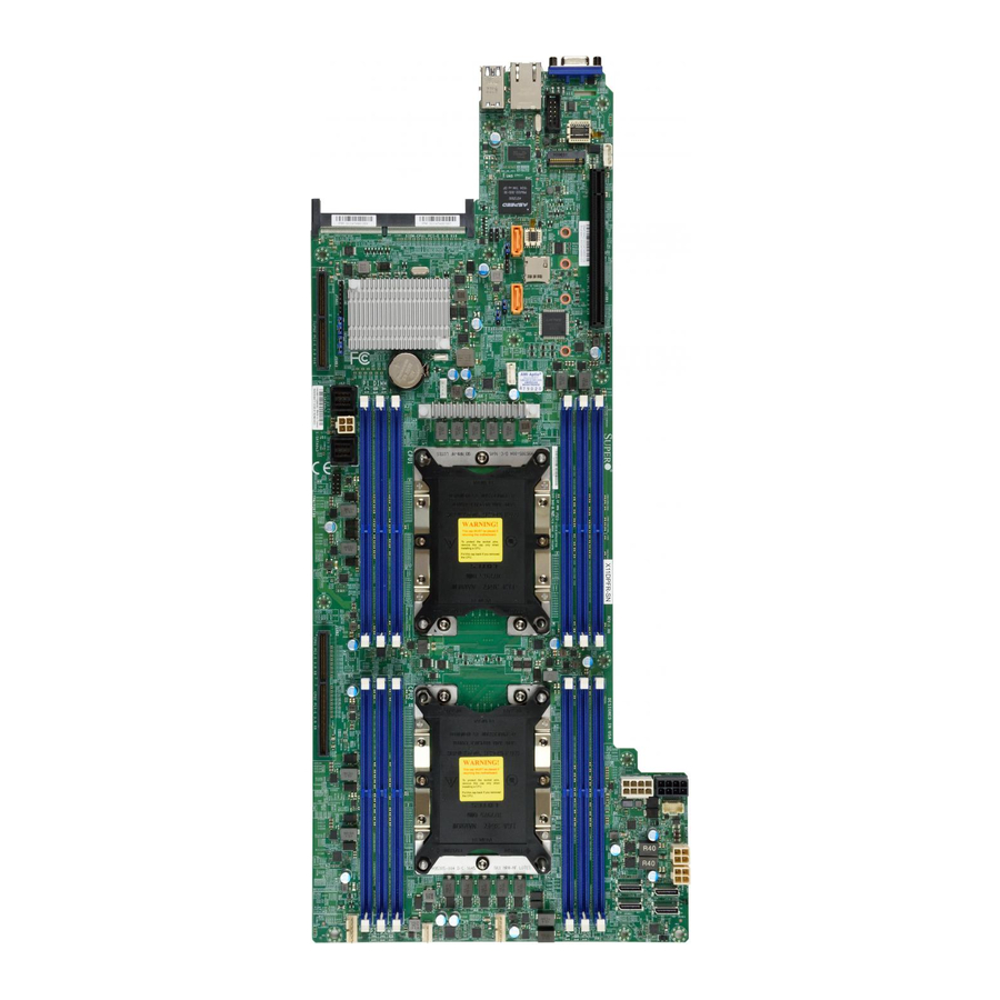
Introduction Congratulations on purchasing your computer motherboard from an industry leader. Supermicro motherboards are designed to provide you with the highest standards in quality and performance. Note: This motherboard was designed to be a part of an integrated server solution. - Page 9 Chapter 1: Introduction Figure 1-1. Motherboard Image Note: All graphics shown in this manual were based upon the latest PCB revision available at the time of publication of the manual. The motherboard you received may or may not look exactly the same as the graphics shown in this manual.
- Page 10 X11DPFR-S(N) User's Manual Figure 1-2. X11DPFR-S(N) Motherboard Layout (not drawn to scale) UID_LED1 USB0/1 (3.0) IPMI_LAN1 COM1 LED1 BMC_HB_LED1 BIOS JPP1/JTAG SCAN JSIOM1 JPP0/JTAG SCAN JSDCARD1 JBT1 JRK1 X11DPFR-S(N) DESIGNED IN USA REV:1.00 CPU1 CPU2 JPWR9 JPWR10 JPWR_HDD2 JPWR_HDD1 JNVME1 JNVME3 FAN1 FAN3...
-
Page 11: Quick Reference
Chapter 1: Introduction Quick Reference UIDLED1 UID_LED1 USB0/1 USB0/1 (3.0) IPMI_LAN1 JPG1 COM1 IPMI LAN COM1 JIPMB1 JPB1 LED1 BMC_HB_LED1 LED1 BMC_HB_LED1 JVRM1 JVRM2 JSXB1 BIOS S_SATA1 JPP1/JTAG SCAN JSIOM1 JPP0/JTAG SCAN JSIOM1 JSDCARD1 JSDCARD1 S_SATA0 JSXB3 JBT1 JPME1 JBT1 JCPLD1 JRK1 JNVI2C1... -
Page 12: Quick Reference Table
X11DPFR-S(N) User's Manual Quick Reference Table Jumper Description Default Setting JBT1 Clear CMOS Open (Normal) JPME1 ME Recovery Pins 1-2 (Normal) JVRM1 VRM SMB Clock (to BMC or PCH) Pins 1-2 (BMC, Normal) JVRM2 VRM SMB Data (to BMC or PCH) Pins 1-2 (BMC, Normal) Connector Description... -
Page 13: Motherboard Features
DIMM Size • Up to 128GB at 1.2V Note 1: Memory speed support depends on the processors used in the system. Note 2: For the latest CPU/memory updates, please refer to our website at http://www.supermicro.com/products/ motherboard. Chipset • Intel C621 Expansion Slots •... - Page 14 • Power-on mode for AC power recovery • Intel® Intelligent Power Node Manager 3.0 (available when the Supermicro Power Manager [SPM] is installed and a special power supply is used. See the note on page 20.) • Management Engine (ME) System Health Monitoring •...
- Page 15 User's Guide available at http://www.supermicro.com/support/manuals/. Note 3: It is strongly recommended that you change BMC log-in information upon initial system power-on. The manufacture default username is ADMIN and the password is ADMIN. For proper BMC configuration, please refer to http://www.supermicro.com/ products/info/files/IPMI/Best_Practices_BMC_Security.pdf...
-
Page 16: System Block Diagram
X11DPFR-S(N) User's Manual Figure 1-3. System Block Diagram VCCP0 12v VCCP1 12v VR13 VR13 5+1 PHASE 5+1 PHASE 165W 165W 10.4/11.2G PCI-E X16 PCI-E X8 PCI-E X4 X4 X4 X4 PCI-E X16 PCI-E x16 PCI-E X8 DMI3 6.0 Gb/S S-SATA x2 SIOM PCI-E X1 SATA-DOM... -
Page 17: Processor And Chipset Overview
Chapter 1: Introduction 1.2 Processor and Chipset Overview Built upon the functionality and capability of the Intel Xeon 81xx/61xx/51xx/41xx/31xx series processors (Socket P) and the Intel C621 chipset, the X11DPFR-S(N) motherboard provides system performance, power efficiency, and feature sets to address the needs of next-generation computer users. -
Page 18: Recovery From Ac Power Loss
X11DPFR-S(N) User's Manual Recovery from AC Power Loss The Basic I/O System (BIOS) provides a setting that determines how the system will respond when AC power is lost and then restored to the system. You can choose for the system to remain powered off (in which case you must press the power switch to turn it back on), or for it to automatically return to the power-on state. -
Page 19: System Resource Alert
Chapter 1: Introduction System Resource Alert This feature is available when used with SuperDoctor 5 . SuperDoctor 5 is used to notify the ® user of certain system events. For example, you can configure SuperDoctor 5 to provide you with warnings when the system temperature, CPU temperatures, voltages and fan speeds go beyond a predefined range. -
Page 20: Advanced Power Management
Intelligent Power Node Manager (IPNM) ® Available when the Supermicro Power Manager (SPM) is installed, Intel's Intelligent Power Node Manager (IPNM) provides your system with real-time thermal control and power management for maximum energy efficiency. Although IPNM Specification Version 2.0/3.0 is supported by the BMC (Baseboard Management Controller), your system must also have IPNM-compatible Management Engine (ME) firmware installed to use this feature. -
Page 21: Chapter 2 Installation
Chapter 2: Installation Chapter 2 Installation 2.1 Static-Sensitive Devices Electrostatic Discharge (ESD) can damage electronic com ponents. To avoid damaging your motherboard and your system, it is important to handle it very carefully. The following measures are generally sufficient to protect your equipment from ESD. Precautions •... -
Page 22: Motherboard Installation
X11DPFR-S(N) User's Manual 2.2 Motherboard Installation All motherboards have standard mounting holes to fit different types of chassis. Make sure that the locations of all the mounting holes for both the motherboard and the chassis match. Although a chassis may have both plastic and metal mounting fasteners, metal ones are highly recommended because they ground the motherboard to the chassis. -
Page 23: Installing The Motherboard
Chapter 2: Installation Installing the Motherboard 1. Install the I/O shield into the back of the chassis. 2. Locate the mounting holes on the motherboard. See the previous page for the location. 3. Locate the matching mounting holes on the chassis. Align the mounting holes on the motherboard against the mounting holes on the chassis. -
Page 24: Processor And Heatsink Installation
When receiving a motherboard without a processor pre-installed, make sure that the plastic CPU socket cap is in place and none of the socket pins are bent; otherwise, contact your retailer immediately. • Refer to the Supermicro website for updates on CPU support. The Processor 81xx/61xx/51xx/41xx/31xx (The Processor) Note: All graphics, drawings and pictures shown in this manual are for illustration only. -
Page 25: Overview Of The Processor Socket Assembly
Chapter 2: Installation Overview of the Processor Socket Assembly The processor socket assembly contains 1) the 81xx/61xx/51xx/41xx/31xx processor 2) CPU/ heatsink carrier, 3) dust cover, and 4) CPU socket. 81xx/61xx/51xx/41xx/31xx Processor 2. CPU/Heatsink Carrier 3. Dust Cover 4. CPU Socket CPU Socket Assembly Note: Be sure to cover the CPU socket with the dust cover when the CPU is not in- stalled. -
Page 26: Overview Of The Processor Heatsink Module
X11DPFR-S(N) User's Manual Overview of the Processor Heatsink Module The processor heatsink module (PHM) contains 1) a passive heatsink, 2) a CPU/heatsink carrier, and 3) The 81xx/61xx/51xx/41xx/31xx Processor. 1. Passive Heatsink 2. CPU/Heatsink Carrier 81xx/61xx/51xx/41xx/31xx Processor Processor Heatsink Module (Bottom View) -
Page 27: Preparing The Cpu Socket For Installation
Chapter 2: Installation Preparing the CPU Socket for Installation This motherboard comes with the CPU socket pre-assembled in the factory. The CPU socket contains 1) a dust cover, 2) a socket bracket, 3) the CPU (LGA3647) socket, and 4) a back plate. -
Page 28: Attaching The Processor To The Cpu/Heatsink Carrier
X11DPFR-S(N) User's Manual Attaching the Processor to the CPU/Heatsink Carrier To properly install the CPU onto the CPU/heatsink carrier, please follow the steps below. 1. Locate Pin 1 (Notch A), Notch B, and Notch C on the CPU and locate Pin 1 (Notch A), Notch B, and Notch C on the CPU/heatsink carrier. -
Page 29: Attaching The Cpu/Carrier Assembly To The Passive Heatsink To Form The Processor Heatsink Module (Phm)
Chapter 2: Installation Attaching the CPU/Carrier Assembly to the Passive Heatsink to Form the Processor Heatsink Module (PHM) After you have made a CPU/carrier assembly, please follow the steps below to mount the assembly onto the heatsink to create the Processor Heatsink Module (PHM). 1. -
Page 30: Installing The Processor Heatsink Module (Phm)
X11DPFR-S(N) User's Manual Installing the Processor Heatsink Module (PHM) 1. Once you have assembled the processor heatsink module (PHM) by following the instructions listed on the previous page, align the processor heatsink module with the CPU socket on the motherboard. 2. -
Page 31: Removing The Processor Heatsink Module (Phm)
Chapter 2: Installation Removing the Processor Heatsink Module (PHM) Before starting to remove the processor heatsink module (PHM), unplug power cord from the power outlet. 1. Using a T30-size star driver, turn the screws on the PHM counterclockwise to loosen it from the socket, starting with screw marked #4 (in the sequence of 4, 3, 2, 1). -
Page 32: Memory Support And Installation
X11DPFR-S(N) User's Manual 2.4 Memory Support and Installation Note: Check the Supermicro website for recommended memory modules. Important: Exercise extreme care when installing or removing DIMM modules to pre- vent any damage. Memory Support The X11DPFR-S(N) supports up to 1.5TB of LRDIMM, Registered DIMM (RDIMM), and Non- Volatile DIMM (NV-DIMM) DDR4 (288-pin) ECC 2666/2400/2133 MHz modules in 12 slots. -
Page 33: Dimm Population Requirements
Chapter 2: Installation DIMM Population Requirements For optimal memory performance, follow the tables below when populating memory modules. Key Parameters for DIMM Configurations Parameters Possible Values Number of Channels 1, 2, 3, 4, 5, or 6 Number of DIMMs per Channel 1DPC (1 DIMM Per Channel) or 2DPC (2 DIMMs Per Channel) DIMM Type RDIMM (w/ECC), LRDIMM, 3DS-LRDIMM... - Page 34 X11DPFR-S(N) User's Manual DDR4 Only Socket Level Population Requirements DDR4 Socket Level Minimum Population Requirements • There should be at least one DDR4 DIMM per socket. • If only one DIMM is populated in a channel, then populate it in the slot furthest away from CPU. •...
- Page 35 Chapter 2: Installation DDR4 Only 2SPC Memory Configuration with x4 DIMMs Total # of DDR Channel Number Adaptive Virtual DIMMs of Ranks Lock Step DIMM Popula- 1 x4 DIMM Must be installed on iMC0 DDR Channel 0 Y, only Bank VLS tion within an >1 Note: Uniformly...
-
Page 36: Dimm Installation
X11DPFR-S(N) User's Manual UID_LED1 DIMM Installation USB0/1 (3.0) IPMI_LAN1 COM1 LED1 BMC_HB_LED1 1. Insert DIMM modules in the following BIOS order: For CPU1, begin with P1-DIMMC1, JPP1/JTAG SCAN JSIOM1 JPP0/JTAG SCAN P1-DIMMB1, P1-DIMMA1 then P1- JSDCARD1 JBT1 DIMMF1, P1-DIMME1, P1-DIMMD1. For CPU2, begin with P2-DIMMC1, P2- JRK1 X11DPFR-S(N) -
Page 37: Rear I/O Ports
Chapter 2: Installation 2.5 Rear I/O Ports See the figure below for the locations and descriptions of the various I/O ports on the rear of the motherboard. UID_LED1 USB0/1 (3.0) IPMI_LAN1 COM1 LED1 BMC_HB_LED1 BIOS JPP1/JTAG SCAN JSIOM1 JPP0/JTAG SCAN JSDCARD1 JBT1 JRK1... - Page 38 Note: UID can also be triggered via IPMI on the motherboard. For more information on IPMI, please refer to the IPMI User's Guide posted on our website at http://www. supermicro.com. UID LED Pin Definitions...
- Page 39 Chapter 2: Installation Universal Serial Bus (USB) Ports There are two USB 3.0 ports (USB0/1) on the I/O back panel. Back Panel USB0/1 (3.0) Pin Definitions Pin# Definition Pin# Definition VBUS Power USB 2.0 Differential Pair Ground Ground of PWR Return StdA_SSRX- SuperSpeed Receiver StdA_SSRX+...
- Page 40 X11DPFR-S(N) User's Manual Ethernet Ports Two LAN ports (LAN1/LAN2) and a dedicated IPMI LAN are located on the I/O back panel. These LAN ports are supported by the onboard AST 2500 BMC and accepts an RJ45 type cable. Refer to the LED Indicator Section for LAN LED information. UID_LED1 USB0/1 (3.0)
- Page 41 Chapter 2: Installation Power Button The Power Button connection is located on pins 1 and 2 of JF1. Momentarily contacting both pins will power on/off the system. This button can also be configured to function as a suspend button (with a setting in the BIOS - see Chapter 4). To turn off the power when the system is in suspend mode, press the button for 4 seconds or longer.
- Page 42 X11DPFR-S(N) User's Manual Power Fail LED The Power Fail LED connection is located on pins 5 and 6 of JF1. Refer to the table below for pin definitions. Power Fail LED Pin Definitions (JF1) Pin# Definition 3.3V PWR Supply Fail Fan Fail and UID LED Connect an LED cable to pins 7 and 8 of the front control panel to use the Overheat/Fan Fail LED connections.
- Page 43 Chapter 2: Installation NIC1/NIC2 (LAN1/LAN2) The NIC (Network Interface Controller) LED connection for LAN port 1 is located on pins 11 and 12 of JF1, and LAN port 2 is on pins 9 and 10. Attach the NIC LED cables here to display network activity.
-
Page 44: Nmi Button
X11DPFR-S(N) User's Manual Power LED The Power LED connection is located on pins 15 and 16 of JF1. Refer to the table below for pin definitions. Power LED Pin Definitions (JF1) Pins Definition 3.3V PWR LED NMI Button The non-maskable interrupt (NMI) button header is located on pins 19 and 20 of JF1. Refer to the table below for pin definitions. -
Page 45: Connectors
Chapter 2: Installation 2.7 Connectors Power Connector 12V 8-pin GPU Power Connectors JPW9-JPW10 are the 8-pin 12V DC power input from the Power Adapter Board. 12V 8-pin Power Pin Definitions Connector Pin# Definition JPWR9 JPWR10 UID_LED1 USB0/1 (3.0) IPMI_LAN1 COM1 LED1 BMC_HB_LED1 BIOS... -
Page 46: Headers
X11DPFR-S(N) User's Manual Headers Onboard Fan Header This motherboard has three fan headers (FAN1~3). This is a 4-pin fan header, which is backward compatible with a traditional 3-pin fan. The onboard fan speed is controlled by Thermal Management (via Hardware Monitoring) in the BIOS. When using Thermal Management setting, please use all 3-pin fans or all 4-pin fans. - Page 47 Chapter 2: Installation TPM Header The JTPM1 header is used to connect a Trusted Platform Module (TPM)/Port 80, which is available from a third-party vendor. A TPM/Port 80 connector is a security device that supports encryption and authentication in hard drives. It allows the motherboard to deny access if the TPM associated with the hard drive is not installed in the system.
- Page 48 X11DPFR-S(N) User's Manual NVMe I C Header JNVI C1 is a sideband header for NVMe devices connected to CPU1. Please connect the C cable to this connector. NVMe OcuLink Connectors Use the four NVMe OcuLink Connectors (JNVME1, JNVME2, JNVME3, JNVME4) to attach high-speed PCI-E storage devices.
- Page 49 Chapter 2: Installation RAID Key Header A RAID Key header is located at JRK1 on the motherboard. The RAID key is used to support onboard NVMe connections. Intel RAID Key Pin Definitions Pins Definition PU 3.3V Stdby PCH RAID KEY UID_LED1 USB0/1 (3.0)
- Page 50 X11DPFR-S(N) User's Manual I-SATA 3.0 and S-SATA 3.0 Ports The X11DPFR-S(N) has two MiniSAS-HD connectors (I-SATA0~3, I-SATA4~7) and two SATADOM ports (S-SATA0/1). These SATA ports are supported by the Intel C621 chipset. UID_LED1 USB0/1 (3.0) IPMI_LAN1 COM1 LED1 BMC_HB_LED1 BIOS JPP1/JTAG SCAN JSIOM1 1.
- Page 51 Chapter 2: Installation Micro SD Card There is one Micro SD memory card slot located at JSDCARD1 on the motherboard. UID_LED1 USB0/1 (3.0) IPMI_LAN1 COM1 LED1 BMC_HB_LED1 BIOS JPP1/JTAG SCAN JSIOM1 1. JSDCARD1 JPP0/JTAG SCAN JSDCARD1 JBT1 JRK1 X11DPFR-S(N) DESIGNED IN USA REV:1.00 CPU1 CPU2...
-
Page 52: Jumper Settings
X11DPFR-S(N) User's Manual 2.8 Jumper Settings How Jumpers Work To modify the operation of the motherboard, jumpers can be used to choose between optional settings. Jumpers create shorts between two pins to change the function of the connector. Pin 1 is identified with a square solder pad on the printed circuit board. See the diagram at right for an example of jumping pins 1 and 2. - Page 53 Chapter 2: Installation VGA Enable/Disable JPG1 allows you to enable or disable the VGA port using the onboard graphics controller. The default setting is Enabled. VGA Enable/Disable Jumper Settings Jumper Setting Definition Pins 1-2 Enabled Pins 2-3 Disabled UID_LED1 USB0/1 (3.0) IPMI_LAN1 COM1...
- Page 54 X11DPFR-S(N) User's Manual Management Engine (ME) Recovery Use jumper JPME1 to select ME Firmware Recovery mode, which will limit resource allocation for essential system operation only in order to maintain normal power operation and management. In the single operation mode, online upgrade will be available via Recovery mode.
- Page 55 Chapter 2: Installation C Bus for VRM Jumper JVRM1 allows the BMC or the PCH to access CPU and memory VRM controllers. See the table below for jumper settings. Jumper Settings Jumper Setting Definition Pins 1-2 BMC (Normal) Pins 2-3 UID_LED1 USB0/1 (3.0)
-
Page 56: Led Indicators
X11DPFR-S(N) User's Manual 2.9 LED Indicators IPMI LAN LEDs A dedicated IPMI LAN, located on the back panel, has two LED indicators. The amber LED on the right of the IPMI LAN port indicates activity, while the LED on the left indicates the speed of the connection. - Page 57 Chapter 2: Installation BMC Heartbeat LED BMC_HB_LED1 is the BMC heartbeat LED. When the LED is blinking green, BMC is functioning normally. See the table below for the LED status. Onboard Power LED Indicator LED Color Definition Green: BMC Normal Blinking UID_LED1 USB0/1...
- Page 58 X11DPFR-S(N) User's Manual Unit ID LED A rear UID LED indicator at UID_LED1 is located near the UID switch on the back panel. This UID indicator provides easy identification of a system.unit that may need service. UID LED LED Indicator LED Color Definition Blue: On...
-
Page 59: Pci-E 3.0 Slots
Chapter 2: Installation 2.10 PCI-E 3.0 Slots PCI-E 3.0 Slots There are several PCI-E slots located on the motherboard. Refer to the layout below for their locations. 1. PCI-E 3.0 x16 Right Riser Card (JSXB1) 2. PCI-E 3.0 x16 (x8+x8) SMCI Proprietary slot (JSXB2) 3. -
Page 60: Chapter 3 Troubleshooting
X11DPFR-S(N) User's Manual Chapter 3 Troubleshooting 3.1 Troubleshooting Procedures Use the following procedures to troubleshoot your system. If you have followed all of the procedures below and still need assistance, refer to the ‘Technical Support Procedures’ and/ or ‘Returning Merchandise for Service’ section(s) in this chapter. Always disconnect the AC power cord before adding, changing or installing any non hot-swap hardware components. -
Page 61: No Video
Chapter 3: Troubleshooting No Video 1. If the power is on but you have no video, remove all the add-on cards and cables. 2. Use the speaker to determine if any beep codes exist. Refer to Appendix A for details on beep codes. -
Page 62: Losing The System's Setup Configuration
2. Memory support: Make sure that the memory modules are supported by testing the modules using memtest86 or a similar utility. Note: Refer to the product page on our website at http:\\www.supermicro.com memory and CPU support and updates. 3. HDD support: Make sure that all hard disk drives (HDDs) work properly. Replace the bad HDDs with good ones. - Page 63 Chapter 3: Troubleshooting 3. Using the minimum configuration for troubleshooting: Remove all unnecessary components (starting with add-on cards first), and use the minimum configuration (but with a CPU and a memory module installed) to identify the trouble areas. Refer to the steps listed in Section A above for proper troubleshooting procedures.
-
Page 64: Technical Support Procedures
X11DPFR-S(N) User's Manual 3.2 Technical Support Procedures Before contacting Technical Support, please take the following steps. Also, note that as a motherboard manufacturer, we do not sell directly to end-users, so it is best to first check with your distributor or reseller for troubleshooting services. They should know of any possible problem(s) with the specific system configuration that was sold to you. -
Page 65: Frequently Asked Questions
Updated BIOS files are located on our website at http://www. supermicro.com. Please check our BIOS warning message and the information on how to update your BIOS on our website. Select your motherboard model and download the BIOS file to your computer. -
Page 66: Battery Removal And Installation
X11DPFR-S(N) User's Manual 3.4 Battery Removal and Installation Battery Removal To remove the onboard battery, follow the steps below: 1. Power off your system and unplug your power cable. 2. Locate the onboard battery as shown below. 3. Using a tool such as a pen or a small screwdriver, push the battery lock outwards to unlock it. -
Page 67: Returning Merchandise For Service
Shipping and handling charges will be applied for all orders that must be mailed when service is complete. For faster service, RMA authorizations may be requested online (http://www.supermicro.com/ support/rma/). This warranty only covers normal consumer use and does not cover damages incurred in shipping or from failure due to the alteration, misuse, abuse or improper maintenance of products. -
Page 68: Chapter 4 Bios
X11DPFR-S(N) User's Manual Chapter 4 BIOS 4.1 Introduction This chapter describes the AMIBIOS™ Setup utility for the X11DPFR-S(N) motherboards. The BIOS is stored on a chip and can be easily upgraded using a flash program. Note: Due to periodic changes to the BIOS, some settings may have been added or deleted and might not yet be recorded in this manual. -
Page 69: Main Setup
Note: The time is in the 24-hour format. For example, 5:30 P.M. appears as 17:30:00. The date's default value is 01/01/2014 after RTC reset. Supermicro X11DPFR-S(N) BIOS Version This item displays the version of the BIOS ROM used in the system. - Page 70 X11DPFR-S(N) User's Manual Memory Information Total Memory This item displays the total size of memory available in the system.
-
Page 71: Advanced Setup Configurations
Chapter 4: BIOS 4.3 Advanced Setup Configurations Use the arrow keys to select the Advanced submenu and press <Enter> to access the submenu items: Warning: Take Caution when changing the Advanced settings. An incorrect value, an incorrect DRAM frequency, or an incorrect BIOS timing setting may cause the system to malfunction. When this occurs, restore the setting to the manufacture default setting. -
Page 72: Power Configuration
X11DPFR-S(N) User's Manual Wait For 'F1' If Error Select Enabled to force the system to wait until the 'F1' key is pressed if an error occurs. The options are Disabled and Enabled. Interrupt 19 (INT19) Trap Response Interrupt 19 is the software interrupt that handles the boot disk function. When this item is set to Immediate, the ROM BIOS of the host adaptors will "capture"... -
Page 73: Cpu Configuration
Chapter 4: BIOS Power Button Function This feature controls how the system shuts down when the power button is pressed. Select 4 Seconds Override for the user to power off the system after pressing and holding the power button for 4 seconds or longer. Select Instant Off to instantly power off the system as soon as the user presses the power button. - Page 74 X11DPFR-S(N) User's Manual Execute Disable Bit (Available if supported by the OS & the CPU) Select Enable to enable Execute Disable Bit support which will allow the processor to designate areas in the system memory where an application code can execute and where it cannot, thus preventing a worm or a virus from flooding illegal codes to overwhelm the processor, damaging the system during a virus attack.
-
Page 75: Advanced Power Management Configuration
Chapter 4: BIOS LLC Prefetch If this feature is set to Enable, LLC (hardware cache) prefetching on all threads will be supported. The options are Disable and Enable. Extended APIC (Extended Advanced Programmable Interrupt Controller) Based on the Intel Hyper-Threading technology, each logical processor (thread) is assigned 256 APIC IDs (APIDs) in 8-bit bandwidth. - Page 76 X11DPFR-S(N) User's Manual Hardware PM (Power Management) State Control Hardware P-States If this feature is set to Disable, hardware will choose a P-state setting for the system based on an OS request. If this feature is set to Native Mode, hardware will choose a P-state setting based on OS guidance.
-
Page 77: Chipset Configuration
Chapter 4: BIOS Chipset Configuration Warning: Setting the wrong values in the following sections may cause the system to malfunc- tion. North Bridge This feature allows the user to configure the settings for the Intel North Bridge. UPI (Ultra Path Interconnect) Configuration ... - Page 78 X11DPFR-S(N) User's Manual Auto, Enable for Remote InvItoM Hybrid Push, InvItoM AllocFlow, Enable for Remote InvItoM Hybrid AllocNonAlloc, and Enable for Remote InvItoM and Remote WViLF. Sub NUMA Clustering (SNC) is a feature that breaks up the Last Level Cache (LLC) into clusters based on address range.
-
Page 79: Memory Configuration
Chapter 4: BIOS Memory Configuration Enforce POR Select POR to enforce POR restrictions for DDR4 memory frequency and voltage programming. The options are POR and Disable. Memory Frequency Use this feature to set the maximum memory frequency for onboard memory modules. The options are Auto, 1866, 2000, 2133, 2200, 2400, 2600, and 2666. - Page 80 X11DPFR-S(N) User's Manual Memory Topology This item displays the information of onboard memory modules as detected by the BIOS. • P1 DIMMA1 • P1 DIMMB1 • P2 DIMMA1 • P2 DIMMB1 Memory RAS (Reliability_Availability_Serviceability) Configuration Use this submenu to configure the following Memory RAS settings. Static Virtual Lockstep Mode Select Enable to support Static Virtual Lockstep mode to enhance memory performance.
-
Page 81: Iio Configuration
Chapter 4: BIOS Patrol Scrub Patrol Scrubbing is a process that allows the CPU to correct correctable memory errors detected in a memory module and send the corrections to the requestor (the original source). When this item is set to Enable, the IO hub will read and write back one cache line every 16K cycles if there is no delay caused by internal processing. - Page 82 X11DPFR-S(N) User's Manual CPU1 PcieBr0D00F0 - Port 0/DMI PcieBr1D00F0 - Port 1A PcieBr2D00F0 - Port 2A PcieBr3D00F0 - Port 3A PcieBr4D00F0 - MCP 0 PcieBr5D00F0 - MCP 1 Link Speed Use this item to select the link speed for the PCI-E port specified by the user. The op- tions are Auto, Gen 1 (2.5 GT/s), Gen 2 (5 GT/s), and Gen 3 (8 GT/s).
- Page 83 Chapter 4: BIOS PCI-E Port Max Payload Size Selecting Auto for this feature will enable the motherboard to automatically detect the maximum Transaction Layer Packet (TLP) size for the connected PCI-E device, allowing for maximum I/O efficiency. Selecting 128B or 256B will designate maximum packet size of 128 or 256.
- Page 84 X11DPFR-S(N) User's Manual PassThrough DMA Select Enable for the Non-Iscoh VT-d engine to pass through DMA (Direct Memory Access) to enhance system performance. The options are Enable and Disable. Select Enable to enable ATS (Address Translation Services) support for the Non-Iscoh VT-d engine to enhance system performance.
- Page 85 Chapter 4: BIOS Hot Plug Capable (Available when the device is detected by the system) Use this feature to enable hot plug support for PCIe root ports 1A~1D. The options are Disable and Enable. VMD Config for PStack1 Intel® VMD for Volume Management Device Select Enable to use the Intel Volume Management Device Technology for this stack.
-
Page 86: South Bridge
X11DPFR-S(N) User's Manual Hot Plug Capable (Available when the device is detected by the system) Select Enable to enable hot plug support for PCIe root ports 3A~3D. This will allow the user to replace the components without shutting down the system. The options are Disable and Enable. -
Page 87: Pch Sata Configuration
Chapter 4: BIOS Legacy USB Support Select Enabled to support onboard legacy USB devices. Select Auto to disable legacy support if there are no legacy USB devices present. Select Disable to have all USB devices available for EFI applications only. The options are Enabled, Disabled and Auto. XHCI Hand-Off This is a work-around solution for operating systems that do not support XHCI (Extensible Host Controller Interface) hand-off. - Page 88 X11DPFR-S(N) User's Manual SATA HDD Unlock Select Enable to unlock SATA HDD password in the OS. The options are Enable and Disable. SATA/sSATA RAID Boot Select (Available when the item "Configure SATA as" is set to "RAID") This feature allows the user to decide which controller should be used for system boot. The options are None, SATA Controller, sSATA Controller, and Both.
- Page 89 Chapter 4: BIOS sSATA Controller This item enables or disables the onboard sSATA controller supported by the Intel SCU. The options are Enable and Disable. Configure sSATA as Select AHCI to configure an sSATA drive specified by the user as an AHCI drive. Select RAID to configure an sSATA drive specified by the user as a RAID drive.
- Page 90 X11DPFR-S(N) User's Manual sSATA Device Type Use this item to specify if the device installed on the sSATA port specified by the user should be connected to a Solid State drive or a Hard Disk Drive. The options are Hard Disk Drive and Solid State Drive.
- Page 91 Chapter 4: BIOS NVMe Firmware Source Use this item to select the NVMe firmware to support system boot. The options are Vendor Defined Firmware and AMI Native Support. The default option, Vendor Defined Firmware, is pre-installed on the drive and may resolve errata or enable innovative functions for the drive.
-
Page 92: Network Stack Configuration
X11DPFR-S(N) User's Manual Onboard SAS Option ROM Use this feature to select which firmware function to be loaded for LAN Port1 used for system boot. The options are Disabled, Legacy, and EFI. Onboard NVMe1 Option ROM Use this feature to select which firmware function to be loaded for NVMe1 used for system boot. -
Page 93: Super Io Configuration
Chapter 4: BIOS Ipv6 HTTP Support Select Enabled to enable Ipv6 HTTP boot support. If this feature is disabled, it will not create the Ipv6 HTTP boot option. The options are Enabled and Disabled. PXE Boot Wait Time Use this feature to select the wait time to press the <ESC> key to abort the PXE boot. The default is 0. -
Page 94: Serial Port Console Redirection
X11DPFR-S(N) User's Manual Serial Port Select Enabled to enable the onboard serial port specified by the user. The options are Enabled and Disabled. Device Settings This item displays the base I/O port address and the Interrupt Request address of a serial port specified by the user. - Page 95 Chapter 4: BIOS Bits Per second Use this feature to set the transmission speed for a serial port used in Console Redirection. Make sure that the same speed is used in the host computer and the client computer. A lower transmission speed may be required for long and busy lines. The options are 9600, 19200, 38400, 57600 and 115200 (bits per second).
- Page 96 X11DPFR-S(N) User's Manual Legacy OS Redirection Resolution Use this feature to select the number of rows and columns used in Console Redirection for legacy OS support. The options are 80x24 and 80x25. Putty KeyPad This feature selects Function Keys and KeyPad settings for Putty, which is a terminal emulator designed for the Windows OS.
- Page 97 Chapter 4: BIOS Data Bits Use this feature to set the data transmission size for Console Redirection. The options are 7 (Bits) and 8 (Bits). Parity A parity bit can be sent along with regular data bits to detect data transmission errors. Select Even if the parity bit is set to 0, and the number of 1's in data bits is even.
- Page 98 X11DPFR-S(N) User's Manual Redirection After BIOS Post Use this feature to enable or disable legacy Console Redirection after BIOS POST (Power-On Self-Test). When this feature is set to Bootloader, legacy Console Redirection is disabled before booting the OS. When this feature is set to Always Enable, legacy Console Redirection remains enabled upon OS boot.
-
Page 99: Acpi Settings
Chapter 4: BIOS Bits Per Second This feature sets the transmission speed for a serial port used in Console Redirection. Make sure that the same speed is used in both host computer and the client computer. A lower transmission speed may be required for long and busy lines. The options are 9600, 19200, 57600, and 115200 (bits per second). - Page 100 X11DPFR-S(N) User's Manual Trusted Computing (Available when a TPM device is installed and detected by the BIOS) When a TPM (Trusted-Platform Module) device is detected in your machine, the following information will be displayed. • TPM2.0 Device Found • Vendor •...
- Page 101 Chapter 4: BIOS Pending Operation Use this feature to schedule a TPM-related operation to be performed by a security (TPM) device at the next system boot to enhance system data integrity. Your system will reboot to carry out a pending TPM operation. The options are None and TPM Clear. Note: Your system will reboot to carry out a pending TPM operation.
-
Page 102: Iscsi Configuration
EV DFX (Device Function On-Hide) support for the system to work properly. (EV DFX is under "IIO Configuration" in the "Chipset/North Bridge" submenu). Note 2: For more information on TPM, please refer to the TPM manual at http://www. supermicro.com/manuals/other. iSCSI Configuration ... -
Page 103: Event Logs
Chapter 4: BIOS 4.4 Event Logs Use this feature to configure Event Log settings. Change SMBIOS Event Log Settings Enabling/Disabling Options SMBIOS Event Log Select Enabled to enable SMBIOS (System Management BIOS) Event Logging during system boot. The options are Enabled and Disabled. Erasing Settings Erase Event Log Select Enabled to erase all error events in the SMBIOS (System Management BIOS) log... -
Page 104: View System Event Log
X11DPFR-S(N) User's Manual SMBIOS Event Log Standard Settings Log System Boot Event Select Enabled to log system boot events. The options are Enabled and Disabled. MECI (Multiple Event Count Increment) Enter the increment value for the multiple event counter. Enter a number between 1 to 255. The default setting is 1. -
Page 105: Ipmi
Chapter 4: BIOS 4.5 IPMI Use this feature to configure Intelligent Platform Management Interface (IPMI) settings. When you select this submenu and press the <Enter> key, the following information will display: • IPMI Firmware Revision: This item indicates the IPMI firmware revision used in your system. •... -
Page 106: Bmc Network Configuration
X11DPFR-S(N) User's Manual When SEL is Full This feature allows the user to determine what the BIOS should do when the system event log is full. Select Erase Immediately to erase all events in the log when the system event log is full. - Page 107 Chapter 4: BIOS Station IP Address This item displays the Station IP address for this computer. This should be in decimal and in dotted quad form (i.e., 192.168.10.253). Subnet Mask This item displays the sub-network that this computer belongs to. The value of each three- digit number separated by dots should not exceed 255.
-
Page 108: Security Settings
X11DPFR-S(N) User's Manual 4.6 Security Settings This menu allows the user to configure the following security settings for the system. Administrator Password Use this feature to set the administrator password which is required to enter the BIOS setup utility. The length of the password should be from 3 characters to 20 characters long. User Password Use this feature to set the user password which is required to enter the BIOS setup utility. -
Page 109: Key Management
Chapter 4: BIOS Attempt Secure Boot If this item is set to Enabled, Secure Boot will be activated when a Platform Key (PK) is entered. A Platform Key is a security key used to manage the security settings of the platform firmware used in your system. -
Page 110: Authorized Signatures
X11DPFR-S(N) User's Manual Key Exchange Keys This feature allows the user to enter and configure a set of values to be used as a Key- Exchange-Keys for the system. This set of values also indicate the size, the keys numbers, and the key source of the Key-Exchange-Keys. -
Page 111: Boot Settings
Chapter 4: BIOS 4.7 Boot Settings Use this feature to configure Boot Settings: Boot Mode Select Use this feature to select the type of devices that the system is going to boot from. The options are Legacy, UEFI (Unified Extensible Firmware Interface), and Dual. Legacy to EFI Support Select Enabled to boot EFI OS support after Legacy boot order has failed. -
Page 112: Delete Boot Option
X11DPFR-S(N) User's Manual Delete Boot Option Use this feature to select a boot device to delete from the boot priority list. Delete Boot Option Use this feature to remove an EFI boot option from the boot priority list. UEFI Application Boot Priorities This feature sets the system boot order of detected devices. -
Page 113: Save & Exit
Chapter 4: BIOS 4.8 Save & Exit Select the Save & Exit tab from the BIOS setup screen to configure the settings below. Save Options Discard Changes and Exit Select this option to quit the BIOS setup without making any permanent changes to the system configuration and reboot the computer. - Page 114 X11DPFR-S(N) User's Manual Default Options Restore Optimized Defaults To set this feature, select Restore Defaults from the Exit menu and press <Enter> to load manufacturer default settings which are intended for maximum system performance but not for maximum stability. Save As User Defaults To set this feature, select Save as User Defaults from the Exit menu and press <Enter>.
-
Page 115: Appendix A Bios Codes
Appendix A: BIOS Codes Appendix A BIOS Codes A.1 BIOS Error POST (Beep) Codes During the POST (Power-On Self-Test) routines, which are performed each time the system is powered on, errors may occur. Non-fatal errors are those which, in most cases, allow the system to continue the boot-up process. - Page 116 When BIOS performs the Power On Self Test, it writes checkpoint codes to I/O port 0080h. If the computer cannot complete the boot process, a diagnostic card can be attached to the computer to read I/O port 0080h (Supermicro p/n AOC-LPC80-20). For information on AMI updates, please refer to http://www.ami.com/products/.
-
Page 117: Appendix B Software Installation
Appendix B Software Installation B.1 Installing Software Programs The Supermicro FTP site contains drivers and utilities for your system at ftp://ftp.supermicro. com. Some of these must be installed, such as the chipset driver. After accessing the FTP site, go into the CDR_Images directory and locate the ISO file for your motherboard. -
Page 118: Superdoctor ® 5
SATA settings back to your original settings. B.2 SuperDoctor ® The Supermicro SuperDoctor 5 is a hardware monitoring program that functions in a command-line or web-based interface in Windows and Linux operating systems. The program monitors system health information such as CPU temperature, system voltages, system power consumption, fan speed, and provides alerts via email or Simple Network Management Protocol (SNMP). -
Page 119: Battery Handling
The following statements are industry standard warnings, provided to warn the user of situations which have the potential for bodily injury. Should you have questions or experience difficulty, contact Supermicro's Technical Support department for assistance. Only certified technicians should attempt to install or configure components. - Page 120 X11DPFR-S(N) User's Manual Attention Danger d'explosion si la pile n'est pas remplacée correctement. Ne la remplacer que par une pile de type semblable ou équivalent, recommandée par le fabricant. Jeter les piles usagées conformément aux instructions du fabricant. ¡Advertencia! Existe peligro de explosión si la batería se reemplaza de manera incorrecta. Reemplazar la batería exclusivamente con el mismo tipo o el equivalente recomendado por el fabricante.
-
Page 121: Product Disposal
Appendix C: Warning Statements Product Disposal Warning! Ultimate disposal of this product should be handled according to all national laws and regulations. 製品の廃棄 この製品を廃棄処分する場合、 国の関係する全ての法律 ・ 条例に従い処理する必要があります。 警告 本产品的废弃处理应根据所有国家的法律和规章进行。 警告 本產品的廢棄處理應根據所有國家的法律和規章進行。 Warnung Die Entsorgung dieses Produkts sollte gemäß allen Bestimmungen und Gesetzen des Landes erfolgen. -
Page 122: Appendix D Uefi Bios Recovery
Warning: Do not upgrade the BIOS unless your system has a BIOS-related issue. Flashing the wrong BIOS can cause irreparable damage to the system. In no event shall Supermicro be liable for direct, indirect, special, incidental, or consequential damages arising from a BIOS update. - Page 123 USB device or a writable CD/DVD. Note: If you cannot locate the "Super.ROM" file in your drive disk, visit our website at www.supermicro.com to download the BIOS package. Extract the BIOS binary image into a USB flash device and rename it "Super.ROM" for the BIOS recovery use.
- Page 124 X11DPFR-S(N) User Manual 3. After locating the healthy BIOS binary image, the system will enter the BIOS Recovery menu as shown below. Note: At this point, you may decide if you want to start the BIOS recovery. If you decide to proceed with BIOS recovery, follow the procedures below.
- Page 125 Appendix C: UEFI BIOS Recovery 5. After the BIOS recovery process is complete, press any key to reboot the system. 6. Using a different system, extract the BIOS package into a USB flash drive. 7. Press <Del> continuously during system boot to enter the BIOS Setup utility. From the top of the tool bar, select Boot to enter the submenu.
- Page 126 X11DPFR-S(N) User Manual 8. When the UEFI Shell prompt appears, type fs# to change the device directory path. Go to the directory that contains the BIOS package you extracted earlier from Step 6. Enter flash.nsh BIOSname.### at the prompt to start the BIOS update process. Note: Do not interrupt this process until the BIOS flashing is complete.
Need help?
Do you have a question about the X11DPFR-S(N) and is the answer not in the manual?
Questions and answers