
Related Manuals for NXP Semiconductors SLN-VIZN3D-IOT


Summary of Contents for NXP Semiconductors SLN-VIZN3D-IOT
- Page 1 NXP Semiconductors Document identifier: SLN-VIZN3D-IOT-UG User Guide Rev. 0, 01 November 2021 SLN-VIZN3D-IOT Kit User Guide...
-
Page 2: Table Of Contents
6.3.5 Manually save users into flash....................32 6.4 Display configuration....................... 32 6.5 Camera configuration......................33 6.6 Audio configuration........................34 6.7 Configure LED brightness....................... 35 6.7.1 IR LED............................35 6.7.2 White LED..........................36 SLN-VIZN3D-IOT Kit User Guide, Rev. 0, 01 November 2021 User Guide 2 / 47... - Page 3 7.1.1 Adjust face proximity and position.....................43 7.1.2 Debug using log messages.......................43 Chapter 8 Document details................44 8.1 References..........................44 8.2 Acronyms and definitions......................44 Chapter 9 Revision history...................46 SLN-VIZN3D-IOT Kit User Guide, Rev. 0, 01 November 2021 User Guide 3 / 47...
-
Page 4: Chapter 1 Introduction
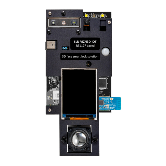
RT1170 microcontroller (MCU) family, running a Real-Time Operating System (RTOS) at up to 1 GHz clock rates, with 2 MB on-chip SRAM. This 3D face recognition solution Software Development Kit (SDK), also called SLN-VIZN3D-IOT, provides OEMs with a fully integrated, self-contained, software, and hardware solution that includes pre-integrated machine learning face-recognition algorithms, as well as all required drivers for all necessary peripherals, including memories, cameras, display, and Bluetooth Low Energy (BLE) chipset. - Page 5 Figure 1. SLN-VIZN3D-IOT main board callout The SLN-VIZN3D-IOT kit comes fully assembled with both a 3D camera and an RGB camera module, a 2.4 inch TFT display, and a speaker to allow for rapid prototyping of any smart lock project with 3D face-recognition capabilities. These additional peripherals...
- Page 6 Depending on the mode of operation, the VIZN3D kit can emit highly concentrated white or non-visible infrared light which can be hazardous to human eyes. Products which incorporate these devices must follow the safety precautions given in IEC 60825-1 and IEC 62471. SLN-VIZN3D-IOT Kit User Guide, Rev. 0, 01 November 2021 User Guide 6 / 47...
-
Page 7: Chapter 2 Recommendations
EUROPEAN DECLARATION OF CONFORMITY (Simplified DoC per Article 10.9 of the Radio Equipment Directive 2014/53/EU) This apparatus, namely SLN-VIZN3D-IOT, conforms to the Radio Equipment Directive 2014/53/EU. The full EU Declaration of Conformity for this apparatus can be found at this location: http://www.nxp.com/mcu-vision3d... -
Page 8: Chapter 3 Getting Started With Sln-Vizn3D-Iot
Getting started with SLN-VIZN3D-IOT 3.1 Box contents The SLN-VIZN3D-IOT kit is delivered fully assembled in a box with a printed quick start card and a USB-C cable. Figure 3. SLN-VIZN3D-IOT box contents Check your kit for damage or marks, and if you find any, contact your NXP representative. - Page 9 Getting started with SLN-VIZN3D-IOT Figure 5. Powering the SLN-VIZN3D-IOT kit When connected, the RGB camera video appears, framed with some application settings. Figure 6. Boot phase completed SLN-VIZN3D-IOT Kit User Guide, Rev. 0, 01 November 2021 User Guide 9 / 47...
-
Page 10: Chapter 4 Local Face Management
Chapter 4 Local face management To evaluate the smart-lock application pre-programmed on the SLN-VIZN3D-IOT kit, you must first register a face. 4.1 Registering a face The onboard pushbuttons are pre-configured to allow direct access to some of the kit’s most useful features, like face registering... - Page 11 “Recognition Successful” message in green, the lock icon in the bottom left corner turns from red/locked to green/unlocked, and the speaker plays an audio message, confirming that a face is successfully recognized. SLN-VIZN3D-IOT Kit User Guide, Rev. 0, 01 November 2021 User Guide...
-
Page 12: Deregistering A Face
A timeout counter represented by a blue bar starts to count down. To de-register your face, look straight-on to the camera and align your face in the bounding box presented by the UI. SLN-VIZN3D-IOT Kit User Guide, Rev. 0, 01 November 2021 User Guide... - Page 13 If your face fails to de-register due to the de-registration being canceled or timing out, the speaker plays an error message and the screen displays a message in red, as shown in Figure SLN-VIZN3D-IOT Kit User Guide, Rev. 0, 01 November 2021 User Guide 13 / 47...
-
Page 14: Liveness Detection
4.3 Liveness detection The 3D Smart Lock application preprogrammed in the SLN-VIZN3D-IOT kit comes with the liveness detection activated by default to make the most of the security features of the 3D camera. This solution can discern between an actual face and a printout, phone display picture, or 3D cast-mold of a face. - Page 15 NXP Semiconductors Local face management Figure 17. 3D camera depth and IR views SLN-VIZN3D-IOT Kit User Guide, Rev. 0, 01 November 2021 User Guide 15 / 47...
-
Page 16: Chapter 5 Remote Face Management
Android phone/tablet application. The Smart Lock Manager app for Android smartphones and tablets offers a friendly interface where you can both register new faces remotely and manage faces that are already registered in the SLN-VIZN3D-IOT’s local face database. This section describes some major features provided by this dedicated Android app. -
Page 17: Managing Kits
5.2 Managing kits To interact with your SLN-VIZN3D-IOT kit, pair your kit with the Smart Lock Manager app. This can be done from the app's main menu. Press the “Device Scan” button to detect the VIZN3D devices that are within the Bluetooth range of your Android device. - Page 18 Figure 21. Pairing with a new smart lock Before accessing your device, enter a password to secure the connection between your Android device and the SLN-VIZN3D-IOT kit you want to access. By default, this password is "000000". Figure 22. Smart lock password screen When (securely) connected with the VIZN3D device, the Android app displays a list of users currently registered in the kit’s local...
-
Page 19: Managing Users
Figure 24. Changing smart lock password 5.3 Managing users The Smart Lock Manager app can remotely manage the users registered to the SLN-VIZN3D-IOT kit using an Android device. This includes adding, listing, and deleting users from the SLN-VIZN3D-IOT’s local face database using 2-way synchronization. - Page 20 The app asks you to type a name of the new face. Tap the blue checkmark icon and select “Register” to finalize the registration. Figure 27. Adding name of the new face SLN-VIZN3D-IOT Kit User Guide, Rev. 0, 01 November 2021 User Guide...
-
Page 21: Modifying Users
The Smart Lock Manager app also enables you to modify registered users. From the list of the Smart Lock registered users, select the user that you want to modify. The available options are "Delete User", "Update Name", and "Reregister". SLN-VIZN3D-IOT Kit User Guide, Rev. 0, 01 November 2021 User Guide... -
Page 22: Deleting Users
From the list of the Smart Lock registered users, select the user that you want to delete. To delete the user, select the "Delete User" option and confirm by selecting "Delete" to remove the user. SLN-VIZN3D-IOT Kit User Guide, Rev. 0, 01 November 2021 User Guide... - Page 23 Android device aware of any changes to users that happened locally on the kit. A sync is automatically performed when you connect to a board. SLN-VIZN3D-IOT Kit User Guide, Rev. 0, 01 November 2021 User Guide 23 / 47...
-
Page 24: Chapter 6 Additional Features
Smart Lock application preprogrammed on the SLN-VIZN3D-IOT kit supports low-power features out-of-the-box. 6.1.1 Pushbuttons A user can manually set the SLN-VIZN3D-IOT kit to low-power mode by pressing and holding the SW1 pushbutton located on the back of the kit for >2 s and then releasing it. -
Page 25: Pir Sensor
Figure 37. DIP switch SW8 to select the wake-up source The SLN-VIZN3D-IOT kit also embeds a PIR sensor capable of waking the system when motion is sensed. To activate the PIR sensor (and disable the SW0 pushbutton and QN9090 BLE wake-up sources), change the configuration of the SW8 DIP Switch from 1001 to 0100. -
Page 26: Automatically Enable Low-Power Mode
6.1.3 Automatically enable low-power mode In addition to manually activating the low-power mode setting via the onboard pushbuttons, the SLN-VIZN3D-IOT can also be configured to automatically enter sleep mode. When automatic low-power mode is enabled, the kit uses a combination of timers and other event triggers to determine when it is okay to enter sleep. - Page 27 While low-power mode’s automatic configuration is active and the kit is about to enter sleep, a “Recognition Failed” message like the one shown in the below figure is displayed on the screen as a warning that the SLN-VIZN3D-IOT is entering sleep mode within the next 1.5 seconds.
-
Page 28: Serial Command Line Interface
6.2.1 Connect to the serial command line interface The SLN-VIZN3D-IOT kit supports several serial commands which give users access to the full suite of features the preprogrammed Smart Lock application has to offer. Serial commands can be issued via the kit’s built-in CLI, accessible using a serial terminal emulator like PuTTY or Tera Term. -
Page 29: List Available Commands
Exit program; closes serial terminal until reset Get the version of the current application software version Get the version of the current oasis library version oasis Table continues on the next page... SLN-VIZN3D-IOT Kit User Guide, Rev. 0, 01 November 2021 User Guide 29 / 47... -
Page 30: Manage User Database
ID number, while the “list -c” command will display the total number of registered users. SHELL>> list Saved - Id 0 Name - user_000 Saved - Id 1 Name - Cooper SLN-VIZN3D-IOT Kit User Guide, Rev. 0, 01 November 2021 User Guide 30 / 47... -
Page 31: Manually Add Users
Figure 47. Manually delete next recognized user Alternatively, running the command “del -a” will erase every user previously registered. SHELL>> del -a All users successfully deleted Figure 48. Manually delete every user SLN-VIZN3D-IOT Kit User Guide, Rev. 0, 01 November 2021 User Guide 31 / 47... -
Page 32: Rename Users
6.4 Display configuration The SLN-VIZN3D-IOT kit comes pre-assembled with the Rocktech RK024HH298 VGA portrait 2.4 inch parallel TFT screen, but the graphical interface for the Smart Lock application can also be pushed over USB to a computer screen similar to a regular USB web camera device. -
Page 33: Camera Configuration
Figure 53. Enable panel-based video output command NOTE The SLN-VIZN3D-IOT kits leverage the MIMXRT117F parallel display controller to control the supplied TFT screen with NXP driver/middleware available in the SLN-VIZN3D-IOT SDK package. The VIZN3D board embeds parallel display connectors (J208, J209) compatible with the Rocktech RK043FN02H-CT WQVGA landscape 4.3inch TFT screen with capacitive touch. -
Page 34: Audio Configuration
The Smart Lock application includes audio feedback prompts, which are used alongside the on-screen messages to enhance the user experience or emulate headless use-cases. The SLN-VIZN3D-IOT kit comes pre-assembled with the PUI ASE02808MR-150-R enclosed 2W Speaker with audio circuitry controlled by the RT117F MQS interface. -
Page 35: Configure Led Brightness
6.7.1 IR LED The SLN-VIZN3D-IOT kit embeds an IR LED controlled by an LED driver which can be used to modulate its power according to the lighting conditions. The RT117F uses a PWM signal with a configurable duty cycle set by a serial command to control the LED driver. -
Page 36: White Led
6.8 Configure automatic low-power mode The SLN-VIZN3D-IOT has been optimized for battery powered applications in part by supporting the ability to enter a low-power state either manually, using a pushbutton, or automatically using a combination of timers and other triggers. For more information... - Page 37 With the USB to UART probe connected, use a serial terminal emulator like PuTTY or Tera Term and connect to the COM port associated with the USB to UART convertor using the [115200, 8, 1, N, XON/XOFF] serial settings shown below: SLN-VIZN3D-IOT Kit User Guide, Rev. 0, 01 November 2021 User Guide...
- Page 38 [ 9.612][Debug] - Littlefs mount success [ 9.641][Debug] - --HAL_FlashDev_Littlefs_Init [ 9.756][Debug] - Littlefs directory exists: -17 [ 10.140][Debug] - HAL_GfxDev_Pxp_Register [ 105. 10][Debug] - START camera dev[0] SLN-VIZN3D-IOT Kit User Guide, Rev. 0, 01 November 2021 User Guide 38 / 47...
- Page 39 [ 505238.127][Verbose] - Task:[2] put message:[0x8038AD70]:[5] [ 505238.175][Verbose] - Task:[2] put message:[0x8038AD70]:[5] done [ 505238.199][Info] - ++HAL_CameraDev_CsiOrbbecU1s_Enqueue [ 505238.221][Info] - Submitting empty buffer [ 505238.237][Info] - --HAL_CameraDev_CsiOrbbecU1s_Enqueue SLN-VIZN3D-IOT Kit User Guide, Rev. 0, 01 November 2021 User Guide 39 / 47...
-
Page 40: Get Ble Address
ID- 2 priority- 3 Name- vision_algo_manager ID- 4 priority- 3 Name- output_manager ID- 5 priority- 6 Name- input_manager Figure 73. Inference engine and oasis version commands SLN-VIZN3D-IOT Kit User Guide, Rev. 0, 01 November 2021 User Guide 40 / 47... -
Page 41: Print Version Information
Figure 77. Soft reset command NOTE After any reset of the SLN-VIZN3D-IOT kit, you may need to restart any computer application used to control or communicate with the board (for example, Serial Terminal for USB to Serial Commands, Camera application for UVC mode.). -
Page 42: Terminate The Sln-Vizn3D-Iot Cli
The command “exit” ends the Serial Terminal Program and terminates serial communication with the board until the next power cycle. There is generally no scenario that requires use of this command. SHELL>> exit Figure 78. Exit command SLN-VIZN3D-IOT Kit User Guide, Rev. 0, 01 November 2021 User Guide 42 / 47... -
Page 43: Chapter 7 Troubleshooting
If after following these steps you still cannot identify the cause of the issue, head over to the section of the NXP forum dedicated to the SLN-VIZN3D-IOT kit to reach out for additional assistance. 7.1.1 Adjust face proximity and position Because face recognition makes use of face “identifiers”... -
Page 44: Chapter 8 Document Details
Joint Test Action Group Microcontroller Unit MEMS Micro-Electro-Mechanical System Mass Storage Device Original Equipment Manufacturer Over the Wire One Time Programmable Read-Only Memory Table continues on the next page... SLN-VIZN3D-IOT Kit User Guide, Rev. 0, 01 November 2021 User Guide 44 / 47... - Page 45 NXP Semiconductors Document details Table 6. Acronyms and definitions (continued) Acronym Definition RTOS Real-Time Operating System Software Development Kit UART Universal asynchronous receiver-transmitter SLN-VIZN3D-IOT Kit User Guide, Rev. 0, 01 November 2021 User Guide 45 / 47...
-
Page 46: Chapter 9 Revision History
The following table lists the substantive changes done to this document since the initial release. Table 7. Revision history Revision number Date Substantive changes 01 November 2021 Initial release SLN-VIZN3D-IOT Kit User Guide, Rev. 0, 01 November 2021 User Guide 46 / 47... - Page 47 Right to make changes - NXP Semiconductors reserves the right to make changes to information published in this document, including without limitation specifications and product descriptions, at any time and without notice. This document supersedes and replaces all information supplied prior to the publication hereof.
Need help?
Do you have a question about the SLN-VIZN3D-IOT and is the answer not in the manual?
Questions and answers