
Subscribe to Our Youtube Channel
Related Manuals for Nuvico CB-HDE21N-L


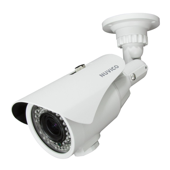
Summary of Contents for Nuvico CB-HDE21N-L
- Page 1 HI-RESOLUTION Bullet Camera CB-HDE21N-L / CB-HDE21P-L CB-HDE65N-L / CB-HDE65P-L CB-HD39N-L / CB-HD39P-L INSTALLATION MANUAL...
-
Page 3: Disclaimer
NUVICO. • NUVICO makes no warranties for damages resulting from corrupted or lost data due to a mistaken operation or malfunction of the cameras, peripheral devices, or unapproved/un supported devices. -
Page 4: Warning And Caution
Warning and Caution WARNING! TO REDUCE THE RISK OF FIRE OR ELECTRIC SHOCK, DO NOT EXPOSE THIS PRODUCT TO RAIN OR MOISTURE. DO NOT INSERT ANY METALLIC OBJECTS THROUGH THE VENTILATION GRILLS OR OPENINGS ON THE EQUIPMENT. CAUTION! The lightning flash with arrowhead symbol, within an equilateral triangle, is intended to alert the user to the presence of uninsulated “dangerous voltage”... -
Page 5: Important Safeguards
Important Safeguards • Read these instructions. • Heed all warnings. • Follow all instructions. • Do not use this equipment near water. • Clean only with dry cloth. • Do not block any ventilation openings. Install in accordance with the manufacturer’s instructions. -
Page 6: Table Of Contents
Table of Contents Disclaimer ....................3 Warning and Caution ................4 Important Safeguards ................5 Table of Contents ..................6 Introduction / Key Features ..............8 Content Verification .................. 9 Parts & Descriptions ................10 Dimensions ..................... 11 Adjusting the Pan, Tilt and Rotation ............12 Adjusting the Vari-focal DC Auto Iris Lens .......... - Page 7 7. RESET ..................... 27 8. EXIT ....................27 OSD Menu Tables ................... 28 Technical Specifications ................ 31 CB-HDE21N-L / CB-HDE65N-L | NTSC ........... 32 CB-HDE21P-L / CB-HDE65P-L | PAL............33 CB-HD39N-L | NTSC ................34 CB-HD39P-L | PAL ................. 35...
-
Page 8: Introduction / Key Features
Introduction ABOUT THIS MANUAL Thank you for purchasing our bullet camera. Before installing and using this camera, please read this manual fully and carefully, and be sure to keep it handy for later use. Key Features • 1/3” CCD Sensor •... -
Page 9: Content Verification
Content Verification Before installing the camera, please make sure that all of the following items are included in the box. IR LED Bullet CAMERA 1. Bullet Camera 2. Bullet Camera Sun Shield 3. Installation Manual 4. OSD Controller and Service Cable (CA-ORC) 5. -
Page 10: Parts & Descriptions
Parts & Descriptions Please refer below for the part names described in this manual. Sun Shield Front Case Back Case Service Monitor Output Cap Bracket Power Input (24VAC / 12VDC) Video Output Connector 24VAC / 12VDC For longer, more consistent performance, avoid installation locations prone to direct sunlight. •... -
Page 11: Dimensions
Dimensions Unit: Inch (mm) For the specific camera dimensions, please refer to the diagram below. CB-HDE21N-L / CB-HDE65N-L [IR36 / IR48] 6.14” (156) 4.76” (121) 8.74” (222) 3” (76) 7.91” (201) 3.5” (89.5) 3.93” (100) CB-HD39N-L [IR24] 4.76” (121) 6.14” (156) 7.52”... -
Page 12: Adjusting The Pan, Tilt And Rotation
Adjusting the Pan, Tilt and Rotation Loosen the screw located at the side of the bracket as illustrated below to adjust all three axes at once. Rotation Tilt Rotation Tilt Installing the Sun Shield The Sun Shield is easy to install by lining up the rear slot and sliding it in to place as shown below. -
Page 13: Adjusting The Vari-Focal Dc Auto Iris Lens
Follow the instructions provided below to make lens and brightness adjustments. 1. Using the Zoom and Focus screws make the desired adjustments as shown - Field of View: Tele(T) to Wide(W) - Focus: Infinity( ) to Near (N) CB-HDE21N-L / CB-HDE65N-L Zoom screw Focus screw Focus screw... -
Page 14: Switching The Ir Led On/Off
Switching the IR LED On/Off IR LED Dip Switch This dip switch is used to switch the IR LEDs on or off. Excessive IR reflection may cause the most focused area of the screen to be over- exposed causing “Hot Spots” when a subject gets too close. Adjusting this setting may help compensate for such overexposure problems. -
Page 15: Connecting To Monitors
Connecting to Monitors Follow the diagram below to make proper connections to the CRT monitor or the service monitor. VIDEO OUT POWER IN CCTV MONITOR SERVICE MONITOR OUTPUT SERVICE MONITOR (Not Included) OSD CONTROLLER AND SERVICE CABLE (CA-ORC) • Power Connection - 12VDC/24VAC Dual Voltage (Auto polarity detection and protection) •... -
Page 16: Camera Osd Setup Controls
Camera OSD Setup Controls OSD Controller and Service Cable Gain access the dome camera OSD setup controls using the controller provided with your new camera shown to the right. *Does not require battery for operation. Set Key - Used to access MAIN SETUP menu mode. -
Page 17: Setup
OSD Menu Terms & Settings SETUP The Setup is used to control and adjust the many features and options available on your bullet camera. Read thoroughly before making any adjustments. Note: These options have been pre-configured at the factory for optimal performance. Altering these settings are not recommended. -
Page 18: Exposure
OSD Menu Terms & Settings 2. EXPOSURE (Continued..) 2.1 SHUTTER (AUTO, FLK, 1/60 ^ - a 1/100,000) The SHUTTER speed can be selected manually according to user preference. Faster shutter speed would be desirable to track fast moving objects across your screen. The shutter speed of 1/60(NTSC), or 1/50(PAL) seconds are recommended. •... -
Page 19: White Balance
OSD Menu Terms & Settings 3. WHITE BALANCE This function is used to control the white balance under different lighting conditions. Adjust this setting to calibrate the camera for correct color rendering. The factory default of ‘ATW’ is recommended for optimal performance. SETUP LENS EXPOSURE... -
Page 20: Backlight
OSD Menu Terms & Settings 4. BACKLIGHT This function is used to compensate for exposure problem associated with extremely bright backgrounds causing the subjects to bloom or silhouette. AREA SEL. AREA1 LEVEL AREA STATE MODE ALL DAY GAIN RETURN HEIGHT WIDTH LEFT/RIGHT TOP/BOTTOM... -
Page 21: Image Adj
OSD Menu Terms & Settings 5. IMAGE ADJ. IMAGE ADJ. LENS SHAD. 2DNR MIRROR FONT COLOR CONTRAST SHARPNESS DISPLAY NEG. IMAGES RETURN 5.1 LENS SHAD. (0~255) Convex shape of the lens causes the light to enter unevenly and typically makes the center of the screen brighter than the rest. Adjusting this setting will compensate for this undesirable effect and make the screen more even. -
Page 22: (5.5) Contrast (5.6) Sharpness (5.7) Display (5.8) Neg. Image
OSD Menu Terms & Settings 5. IMAGE ADJ. (Continued..) 5.5 CONTRAST (0~255) Use the CONTRAST function to adjust the contrast in the picture. 5.6 SHARPNESS (0~31) Use the SHARPNESS function to adjust the sharpness of the picture. 5.7 DISPLAY (CRT, LCD, USER) Select the type of display monitor that will be used with the camera. Because CRT monitor will often display pictures brighter than LCD monitor, properly setting this feature will produce the best color and brightness result. -
Page 23: Osd Menu Terms & Setting (Continued)
OSD Menu Terms & Settings 6. SPECIAL The Special Setup is used to control the CAMERA TITLE, DAY& NIGHT, MOTION, PRIVACY, DPC, and display the VERSION number of the dome camera. SPECIAL CAM TITLE DAY&NIGHT AUTO MOTION PRIVACY VERSION 00 00 00 RETURN 6.1 CAM TITLE (On, Off) The CAMERA TITLE is used to assign a number or a custom title to easily identify... - Page 24 OSD Menu Terms & Settings 6. SPECIAL (Continued..) 6.2 DAY&NIGHT (AUTO, COLOR, B/W, EXT) This function is used to control the color setting during daytime and night-time operation. • AUTO: The Color mode is operated during daytime and automatically converts to B/W mode in the absence of light during night-time. DaN Level - This level determines the level D&N AUTO of darkness before switching from Day mode to...
-
Page 25: (6.3) Motion
OSD Menu Terms & Settings 6. SPECIAL (Continued..) 6.3 MOTION (On, Off) This function is used to detect motion in area monitored by the camera. The “Running Man” icon will be displayed on the bottom left corner once motion has been detected. There are 4 pre-defined white boxes representing the areas monitored for motion. Each boxes can be individually adjusted to user preference. -
Page 26: (6.4) Privacy (6.5) Dpc
OSD Menu Terms & Settings 6. SPECIAL (Continued..) 6.4 PRIVACY (On, Off) This function is used to mask specific areas within the frame of the camera to be concealed. There are total of 8 different colored boxes representing the masked areas. Each boxes can be individually adjusted to user preference. PRIVACY AREA SEL. -
Page 27: (6.6) Version
OSD Menu Terms & Settings 6. SPECIAL (Continued..) 6.6 VERSION The camera firmware version is displayed here. 6.7 RETURN Select RET to save and exit, and to go back to the MAIN MENU. 7. RESET This function is used to reset all camera settings to the factory default setting. RESET FACTORY RESET... -
Page 28: Osd Menu Tables
OSD Menu Table OSD Menu At A Glance Use this section of the manual to get quick reference of the OSD menu. Please refer to the previous section for the detailed explanation of the features mentioned below. •... - Page 29 OSD Menu Table •...
- Page 30 OSD Menu Table (*) Asterisk indicates features only available in the LED equipped vari-focal lens model. DAY&NIGHT function is not supported in the standard type cameras. •...
-
Page 31: Technical Specifications
Technical Specifications This page has been intentionally left blank. •... -
Page 32: Cb-Hde21N-L / Cb-Hde65N-L | Ntsc
Technical Specifications | NTSC Technical Specifications CB-HDE21N-L CB-HDE65N-L NTSC Video Format Image Sensor 1/3” CCD Horizontal Resolution 600 TV Lines, 650 TV Lines (B/W) Day/Night Functionality Yes w/ ICR Lens Type (DC Auto Iris) Vari-focal 2.8mm-11mm Vari-focal 6mm-50mm Angle of View 134°(W) ~ 36°(T) -
Page 33: Cb-Hde21P-L / Cb-Hde65P-L | Pal
Technical Specifications | PAL Technical Specifications CB-HDE21P-L CB-HDE65P-L NTSC Video Format Image Sensor 1/3” CCD Horizontal Resolution 600 TV Lines, 650 TV Lines (B/W) Day/Night Functionality Yes w/ ICR Lens Type (DC Auto Iris) Vari-focal 2.8mm-11mm Vari-focal 6mm-50mm Angle of View 134°(W) ~ 36°(T) 54°(W) ~ 7.6°(T) IR LEDs... -
Page 34: Cb-Hd39N-L | Ntsc
Technical Specifications | NTSC Technical Specifications CB-HD39N-L NTSC Video Format Image Sensor 1/3” CCD Horizontal Resolution 600 TV Lines, 650 TV Lines (B/W) Day/Night Functionality Yes w/ ICR Lens Type (DC Auto Iris) Vari-focal 2.8mm-11mm Angle of View 134°(W) ~ 36°(T) IR LEDs IR LEDs Distance Up to 50ft. -
Page 35: Cb-Hd39P-L | Pal
Technical Specifications | PAL Technical Specifications CB-HD39P-L NTSC Video Format Image Sensor 1/3” CCD Horizontal Resolution 600 TV Lines, 650 TV Lines (B/W) Day/Night Functionality Yes w/ ICR Lens Type (DC Auto Iris) Vari-focal 2.8mm-11mm Angle of View 134°(W) ~ 36°(T) IR LEDs IR LEDs Distance Up to 50ft. - Page 36 The NUVICO logo is the registered trademark of NUVICO. © Copyright 2012, NUVICO. All rights reserved. Version 3.0...
Need help?
Do you have a question about the CB-HDE21N-L and is the answer not in the manual?
Questions and answers