Table of Contents
Advertisement
Advertisement
Table of Contents

Related Manuals for Nuvico CB-HD21N-L


Summary of Contents for Nuvico CB-HD21N-L
- Page 2 NUVICO. • NUVICO makes no warranties for damages resulting from corrupted or lost data due to a mistaken operation or malfunction of the cameras, peripheral devices, or unapproved/un supported devices.
-
Page 3: Warning And Caution
Warning and Caution WARNING! TO REDUCE THE RISK OF FIRE OR ELECTRIC SHOCK, DO NOT EXPOSE THIS PRODUCT TO RAIN OR MOISTURE. DO NOT INSERT ANY METALLIC OBJECTS THROUGH THE VENTILATION GRILLS OR OPENINGS ON THE EQUIPMENT. CAUTION! The lightning flash with arrowhead symbol, within an equilateral triangle, is intended to alert the user to the presence of uninsulated “dangerous voltage”... -
Page 4: Important Safeguards
Important Safeguards • Read these instructions. • Heed all warnings. • Follow all instructions. • Do not use this equipment near water. • Clean only with dry cloth. • Do not block any ventilation openings. Install in accordance with the manufacturer’s instructions. -
Page 5: Table Of Contents
Table of Contents ....................Disclaimer ................Warning and Caution ................Important Safeguards ..................Table of Contents ..............Introduction / Key Features ................Content Verification ................Parts & Descriptions ................Camera Dimensions ................Connecting to Monitors ............. Adjusting the Pan, Tilt and Rotation ........... -
Page 6: Introduction / Key Features
Introduction ABOUT THIS MANUAL Thank you for purchasing our camera. Before installing and using this camera, please read this manual fully and carefully, and be sure to keep it handy for later use. Key Features • 1/3” CCD Sensor • 550 TV Lines (Color), 600 TV Lines (B/W) •... -
Page 7: Content Verification
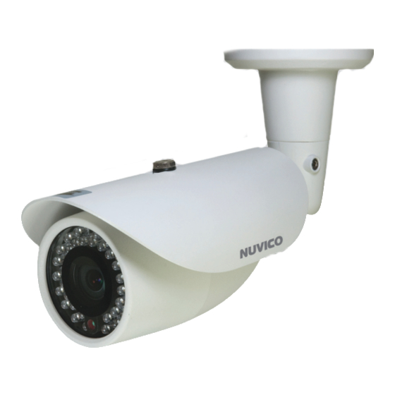
Content Verification Before installing the camera, please make sure that all of the following items are included in the box. IR LED Bullet CAMERA 1. Bullet Camera 2. Bullet Camera Sun Shield 3. Installation Manual 4. Service Monitor Cable - Model#: CA-SMC30 5. -
Page 8: Parts & Descriptions
Parts & Descriptions Bolt Sun Shield Front Case Back Case Service Monitor Output Cap Bracket Power Input (24VAC / 12VDC) 24VAC / 12VDC Video Output Connector For longer, more consistant performance, avoid installation locations prone to direct sunlight. • Color Bullet Camera... -
Page 9: Camera Dimensions
Dimensions Unit: Inch (mm) See the diagrams below for the exact dimensions of the color bullet camera. 3.62” (92) 7.13” (181) 4.05” (103) 6.22” (158) 2.95” (75) 3.43” (87) Color Bullet Camera •... -
Page 10: Connecting To Monitors
Connecting to Monitors Follow the diagram below to make proper connections to the CRT Monitor or the Service Monitor. SERVICE MONITOR SERVICE MONITOR OUTPUT CCTV MONITOR (Not Included) • Power Connection - 12VDC/24VAC Dual Voltage (Auto polarity detection and protection) •... -
Page 11: Adjusting The Pan, Tilt And Rotation
Adjusting the Pan, Tilt and Rotation Loosen the corresponding screws before attempting to make Pan, Tilt and Rotation adjustments. Rotation Screw Tilt Screw Pan Screw Rotation Tilt Color Bullet Camera •... -
Page 12: Adjusting The Vari-Focal Dc Auto Iris Lens
Adjusting the Vari-focal DC Auto Iris Lens Follow the instructions provided below to make any lens adjustments. 1. Unscrew the front case from the back case. 2. Loosen the Zoom and Focus screws and make the desired adjustments as shown below. -
Page 13: Dip Switch Functions And Operation
Dip Switch Functions and Operation Follow the instructions provided below to switch ON/OFF the various available camera functions and modes. Function Dip Switch Function Dip Switch DIP Switch Functions Each Dip Switch represents the IR LEDs On various functions and modes. Switch IR LEDs Off On/Off the various functions and FLK On... -
Page 14: Dip Switch Menu Control Terms
Dip Switch Menu Control Terms A. Switching OFF/ON the IR LEDs This function is used to switch OFF, or switch back ON the IR LEDs. Too much IR reflection from a subject causes over-exposure on the most focused area causing ‘Hot Spots’ within the picture. Switching-off the IR LEDs at times can avoid such problems. -
Page 15: Technical Specifications
Technical Specifications | NTSC / PAL Technical Specifications CB-HD21N-L CB-HD21P-L Video Format NTSC Image Sensor 1/3” CCD 1/3” CCD Horizontal Resolution 550 TVL (Color), 600 TVL (B/W) 550 TVL (Color), 600 TVL (B/W) Day / Night Functionality Yes w/ ICR Yes w/ ICR Vari-focal 2.8mm-10mm...
Need help?
Do you have a question about the CB-HD21N-L and is the answer not in the manual?
Questions and answers