
Related Manuals for Nuvico ZoomMatic CI-Z22N-L


Summary of Contents for Nuvico ZoomMatic CI-Z22N-L
- Page 1 HIGH RESOLUTION 22X AF ZOOM Outdoor Integrated Camera CI-Z22N-L INSTALLATION MANUAL...
-
Page 2: Disclaimer
Disclaimer • While every effort has been made to ensure that the information contained in this guide is accurate and complete, no liability can be accepted for any errors or omis- sions. • NUVICO reserves the right to change the specifications of the hardware and software described herein at any time without prior notice. • No part of this guide may be reproduced, transmitted, transcribed, stored in a retrieval system, or translated into any language in any form, by any means, without prior writ- ten permission of NUVICO. • NUVICO makes no warranties for damages resulting from corrupted or lost data due to a mistaken operation or malfunction of the cameras, peripheral devices, or unap- proved/unsupported devices. -
Page 3: Warning And Caution
Warning and Caution WARNING! TO REDUCE THE RISK OF FIRE OR ELECTRIC SHOCK, DO NOT EXPOSE THIS PRODUCT TO RAIN OR MOISTURE. DO NOT INSERT ANY METALLIC OBJECTS THROUGH THE VENTILATION GRILLS OR OPENINGS ON THE EQUIPMENT. CAUTION! The lightning flash with arrowhead symbol, within an equilateral triangle, is intended to alert the user to the presence of uninsulated “dangerous voltage” within the product’s enclosure that may be of sufficient magnitude to constitute a risk of electric shock to persons. The exclamation point within an equilateral triangle is intended to alert the user to the presence of important operating and maintenance (servicing) instruction in the literature accompanying the product. -
Page 4: Fcc Compliance Statement / Ce Compliance Statement
FCC Compliance Statement FCC INFORMATION : THIS EQUIPMENT HAS BEEN TESTED AND FOUND TO COMPLY WITH THE LIMITS FOR A CLASS A DIGITAL DEVICE, PURSUANT TO PART 15 OF THE FCC RULES. THESE LIMITS ARE DESIGNED TO PROVIDE REASONABLE PROTECTION AGAINST HARMFUL INTERFERENCE WHEN THE EQUIPMENT IS OPERATED IN A COMMERCIAL ENVIRONMENT. THIS EQUIPMENT GENERATES, USES, AND CAN RADIATE RADIO FREQUENCY ENERGY AND IF NOT INSTALLED AND USED IN ACCORDANCE WITH THE INSTRUCTION MANUAL, MAY CAUSE HARMFUL INTERFERENCE TO RADIO COMMUNICATIONS. OPERATION OF THIS EQUIPMENT IN A RESIDENTIAL AREA IS LIKELY TO CAUSE HARMFUL INTERFERENCE IN WHICH CASE THE USER WILL BE REQUIRED TO CORRECT THE INTERFERENCE AT HIS OWN EXPENSE. CAUTION : CHANGES OR MODIFICATIONS NOT EXPRESSLY APPROVED BY THE PARTY RESPONSIBLE FOR COMPLIANCE COULD VOID THE USER’S AUTHORITY TO OPERATE THE EQUIPMENT. THIS CLASS A DIGITAL EQUIPMENT COMPLIES WITH CANADIAN ICES-003. CET APPAREIL NUMÉRIQUE DE LA CLASSE A EST CONFORME À LA NORME NMB-003 DU CANADA. CE Compliance Statement WARNING : THIS IS A CLASS A PRODUCT. IN A DOMESTIC ENVIRONMENT THIS PRODUCT MAY CAUSE RADIO INTERFERENCE IN WHICH CASE THE USER MAY BE REQUIRED TO TAKE ADEQUATE MEASURES... -
Page 5: Important Safeguards
Important Safeguards • Read these instructions. • Heed all warnings. • Follow all instructions. • Do not use this equipment near water. • Clean only with dry cloth. • Do not block any ventilation openings. Install in accordance with the manufacturer’s instructions. • Do not install near any heat sources such as radiators, heat registers, stoves, or other equipment (including amplifiers) that produce heat. • Do not defeat the safety purpose of the polarized or grounding-type plug. A polarized plug has two blades with one wider than the other. A grounding type plug has two blades and a third grounding prong. The wide blade or the third prong is provided for your safety. If the provided plug does not fit into your outlet, consult an electrician for replacement of the obsolete outlet. • Protect the power cord from being walked on or pinched, particularly at plugs, conve- nience receptacles, and the point where they exit from the equipment. • Only use attachments/accessories specified by the manufacturer. • Unplug this equipment during lightning storms or when unused for long periods of time. • Refer all servicing to qualified service personnel. Servicing is required when the equip- ment has been damaged in any way, such as power-supply cord or plug is damaged, liquid has been spilled or objects have fallen into the equipment, the equipment has been exposed to rain or moisture, does not operate normally, or has been dropped. • CAUTION - THIS MANUAL IS FOR USE BY QUALIFIED SERVICE PERSONNEL ONLY.TO REDUCE THE RISK OF ELECTRIC SHOCK DO NOT PERFORM ANY SERVICING OTHER THAN THAT CONTAINED IN THE OPERATING INSTRUCTIONS UNLESS YOU ARE QUALI- FIED TO DO SO. -
Page 6: Table Of Contents
Table of Contents Disclaimer ......................2 Warning and Caution ....................3 FCC Compliance Statement / CE Compliance Statement ........4 Important Safeguards ...................5 Table of Contents ....................6 Introduction ......................8 Content Verification / Dimensions ................9 Connections & Wiring Connecting the ZoomMatic™ Integrated Camera to the Controller ....10 Connecting the ZoomMatic™... - Page 7 Table of Contents 5. SPECIAL 5.1 BACKLIGHT ..................20 5.2 DAY/NIGHT ...................20 5.3 SHARPNESS ..................20 5.4 COMMUNICATION ................21 5.5 FACTORY DEFAULT ................22 5.6 ACCESS CONTROL ................22 6. DISPLAY 6.1 CAMERA TITLE ..................23 6.2 EDIT TITLE ....................23 Programming The CAMERA TITLE ..............24 6.3 CAMERA ID ..................24 6.4 FUNCTION NAME .................24 6.5 ZOOM MAGNIFICATION ................24...
-
Page 8: Introduction
Introduction ABOUT THIS MANUAL Thank you for purchasing our ZoomMatic™ Integrated camera. Our ZoomMatic™ Integrated cameras are all equipped with high resolution 1/4” Interline transfer CCD Imager for enhanced low light sensitivity. A user-friendly, on-screen display (OSD) menu makes it easy to setup and program functions, and automatic motion detection with zoom function and auto focus makes it ideal for monitoring Point-of-Sales, driveways, corridors, alleys, and entrances. 580 TV Lines and powerful wide optical zoom lens delivers crystal clear pictures during the day, and ICR cut-filter and Smart IR LEDs provides flexibility in changing night-time environments while granting excellent pictures even in complete darkness. *Before installing and using this camera, please read this manual fully and carefully, and be sure to keep it handy for later use. Key Features • 1/4” CCD Sensor • 580 TV Lines • 22X A/F Optical Zoom Lens (3.9~85.5mm) • 16X Digital Zoom (Combined total of 352X) • Day/Night Functionality with ICR • Auto Focus & Auto Iris • 0.2 Lux (Color), 0.02 Lux (B/W), 0.00 Lux (IR LED On) • 78 Power IR LEDs • IR Adjustments: On/Off, Intensity Levels (Smart IR) • IR Distance: Up to 300ft. -
Page 9: Content Verification / Dimensions
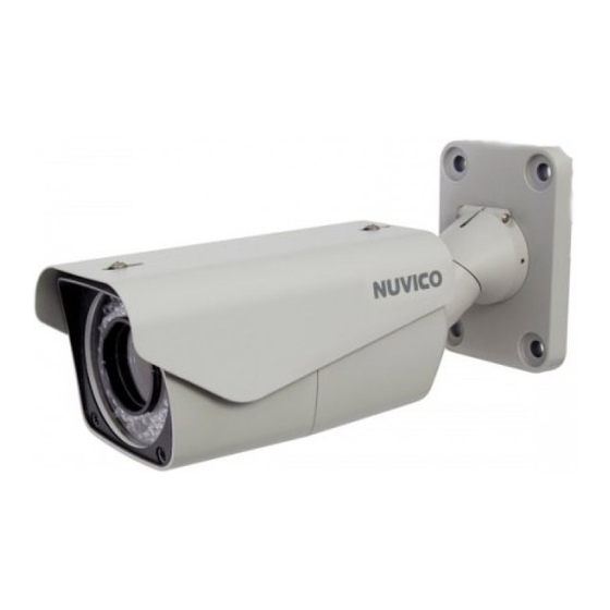
Content Verification Before installing the camera, please make sure that all of the following items are included in the box. ZoomMatic™ Series 1. ZoomMatic™ Integrated Camera 2. Sun Shield 3. Remote Controller 4. Installation Manual 5. Mounting Hardware Dimensions Unit: Inch (mm) 3.94” (100) 2.76” (70) 12.09” (307) 8.26” (210) 5.63” (143) 4.02” (102) 5.63” (143) 4.02” (102) 4.49” (114) 7.60” (193) 3.94” (100) -
Page 10: Connections & Wiring
Connections & Wiring Connecting the ZoomMatic™ Integrated Camera to the Controller Additional Controller Keyboard and a variety of external switching devices such as Multiplexers (MUXes) and Digital Video Recorders (DVRs) may be incorporated to ac- commodate the needs from a small to a large surveillance/security system. The below illustrates sample installation configuration KEYBOARD CONTROLLER... -
Page 11: Connecting The Zoommatic™ Integrated Camera Directly To The Dvr
Connections & Wiring Connecting the ZoomMatic™ Integrated Camera Directly to the DVR • Locate the RS-422 Rx+ & Rx- conductor wire from the ZoomMatic™ Integrated camera. • Connect the RS-485 Tx(+)/ Tx(-) of the DVR into Rx(+)/Rx(-) of the ZoomMatic™ Integrated camera. -
Page 12: Remote Controller Keys & Descriptions
Remote Controller Keys & Descriptions The ZoomMatic™ Integrated camera comes with a remote controller for ease of instal- lation and control. Gain access to the OSD menu to simply modify any feature settings, recall any programmed presets, modify the motion detection sensitivity, or change the IR LED intensity. POWER – Not used NUMBERS – Use Numbers when changing the ID of the remote controller. They are POWER also used to save or recall presets. Camera Address (ID) - Use CAM button to change the ID of the remote controller when controlling multiple cameras. SAVE PRESET Example: To control CAM ID#2, Press 2 and HOME PATTERN SCAN... -
Page 13: Adjusting The Lens & Setup Menu
Adjusting the Lens & Setup Menu Adjusting Via Remote Control Point the remote controller to the camera to control the zoom. Remote controller may be used to enter and make changes in the OSD Setup Menu. Adjusting Via Controller Keyboard Use the controller keyboard (CK-1000) to adjust the zoom by twisting the joystick. You can also enter and make changes in the OSD Setup Menu. Adjusting Via DVR (Digital Video Recorder) Use the DVR’s PTZ menu to adjust the zoom using the + and -. You can also enter and make changes in the OSD Setup Menu. Note: Make sure that the RS485 connection is connected to the Controller or DVR. -
Page 14: Adjusting The 3-Axis Bracket
Adjusting the 3-Axis Bracket Loosen the corresponding screws before attempting to make Pan, Tilt and Rotation adjust- ments. -
Page 15: Osd Menu Controls (On-Screen-Display)
OSD Menu Controls & Navigation 1. OSD MENU CONTROLS (On-Screen-Display) • Menu Key - Used to access Main menu. • p Up / q Down Key - Used to scroll through the desired sub-menu selection and to move the cursor up or down during the OSD menu. • t Left / u Right Key - Used to adjust the desired menu selection, and to move the cursor left or right during the OSD menu. Also used to confirm the setting changes. • ESC Key - Used to exit from the sub-menu without saving. MAIN SETUP FOCUS SPECIAL DISPLAY FUNCTION IR RADIATOR EXIT 1.1 Entering and Navigating the Menus To enter the main menu, press the [MENU] key. To enter the sub-menu, scroll down to the desired sub-menu and press the [u] RIGHT key. Scrolling the available options are accomplished by pressing the corresponding [p/ q] UP/DOWN arrow keys. -
Page 16: Osd Menu Terms & Settings
OSD Menu Terms & Settings 2. FOCUS SETUP The ZoomMatic™ Integrated camera can be set up to automatically focus to the changing environment or just once at a preset field of view. (e.g., a man walking across the monitored area closer to the camera) IMPORTANT: Continuous use of the Auto Focus feature under heavy movement conditions will significantly shorten the lifespan of the lens. -
Page 17: Wb Setup (White Balance)
OSD Menu Terms & Settings 3. WB SETUP (White Balance) The WB SETUP is used to control the white balance under different illumination sources. Adjust this setting to calibrate the camera for correct color rendering. WB SETUP MODE R GAIN B GAIN EXIT 3.1 MODE (ATW, AWC, INDOOR, OUTDOOR, MANUAL) -
Page 18: Ae Setup (Automatic Exposure)
OSD Menu Terms & Settings 4. AE SETUP (Automatic Exposure) The AE Control function is used to control the Iris, Shutter, AGC (Gain), DSS (Slow Shutter), and BRIGHTNESS. It can also be set to AUTO (recommended) or one of 3 other pre-configured settings. -
Page 19: Shutter
OSD Menu Terms & Settings 4.2 SHUTTER (1/60 a ... a F1/100,000) The SHUTTER speed can be selected according to user preference in the SHUTTER and MANUAL modes. The shutter speed of 1/60 (NTSC), or 1/50 (PAL) seconds are recom- mended for most environments. 4.3 IRIS (OPEN, CLOSED, F16.0 a ... a F1.8) The IRIS of the camera can be set to user preference in the IRIS and MANUAL modes. 4.4 AGC - Automatic Gain Control (0 ~ 30) The AGC is automatically controlled in the AUTO, SHUTTER, and the IRIS modes. You can have manual control over the AGC in the MANUAL mode only. This function is used to amplify the video signal when it falls below the set parameter. Increasing the AGC level brightens the overall screen, but a setting too high can produce noise. 4.5 DSS: Digital Slow Shutter (OFF, 2X, 4X a ... a 128X, 256X) The DSS can be set to user preference under any AE mode setting. This function is used to boost the light sensitivity of the camera by slowing down the effective shutter speed. -
Page 20: Special
OSD Menu Terms & Settings 5. SPECIAL The Special Setup is used to control the DAY/NIGHT, SENSING, SHARPNESS, COM- MUNICATION, ACCESS CONTROL, and FACTORY DEFAULT of the Integrated camera. SPECIAL SETUP BACKLIGHT DAY/NIGHT AUTO-L SHARPNESS COMMUNICATION FACTORY DEFAULT ACCESS CONTROL 5.1 BACKLIGHT (OFF, LOW, MID, HIGH). -
Page 21: Communication
OSD Menu Terms & Settings 5.4 COMMUNICATION The function is used to setup the ID, BAUDRATE, PROTOCOL, and set the TERMINATION of the ZoomMatic™ Integrated camera. COMMUNICATION BAUDRATE 9600 PROTOCOL AUTO TERMINATION SAVE and EXIT • ID: Assign the ID number to the camera. Assigning and ID number can easily identify the camera from your DVR or network. The ID number ranges from 1-99. Note: The CAMERA ID under DISPLAY must be set to ON to be visible on the screen. • BAUDRATE: Configure the camera baud rate (2400, 4800, 9600, 19200, 38400, 57600). Baudrate is set to 9600 as the factory default. • PROTOCOL: Assign the protocol to the camera. (AUTO, NUVICO, Pelco-D/P) • TERMINATION: Every device that is connected at the end of the communication data line must be terminated to prevent potential control signal errors. Switch the TERMI- NATION ON or OFF. -
Page 22: Factory Default
OSD Menu Terms & Settings 5.6 FACTORY DEFAULT This function is used to reset all the camera settings to the factory default. This will erase all ‘Camera’ and ‘Function’ programming! Everything will be erased! FACTORY DEFAULT Are you sure ? 5.5 ACCESS CONTROL (REMOTE CONTROL, PASSWORD CHECK, CHANGE PASS- WORD) This function is used to set limitations to the remote control access and to set up a password for additional security measures. ACCESS CONTROL REMOTE CONTROL PASSWORD CHECK CHANGE PASSWORD... -
Page 23: Display
OSD Menu Terms & Settings 6. DISPLAY The Display Setup is used to set the CAMERA TITLE, CAMERA ID, FUNCTION NAME, and ZOOM MAGNIFICATION of the ZoomMatic™ Integrated camera. DISPLAY CAMERA TITLE EDIT TITLE CAMERA ID FUNCTION NAME ZOOM MAGNIFICATION 6.1 CAMERA TITLE This function enables or disables the assigned CAMERA TITLE display on the main screen 6.2 EDIT TITLE... -
Page 24: Programming The Camera Title
OSD Menu Terms & Settings 6.2 EDIT TITLE (Continued..) Programming The CAMERA TITLE 1. Enter the EDIT TITLE screen by highlighting the function and pressing the [ u] RIGHT key to enter the sub-menu. 2. Once the default title appears with cursor blinking below the first letter, navigate using the [q / p / t / u] arrow key on the remote controller to the alphabetical letters, numbers, and symbols, to create a custom title moving one letter at a time to the right. (Maximum 10 characters) 3. Once the desired TITLE has been entered, press [ESC] key to save and exit. 6.3 CAMERA ID This function enables or disables the assigned CAMERA ID display on the main screen 6.4 FUNCTION NAME This function enables or disables the assigned FUNCTION NAME display on the main screen 6.5 ZOOM MAGNIFICATION This function displays the ZOOM MAGNIFICATION factor on the main screen. -
Page 25: Function
OSD Menu Terms & Settings 7. FUNCTION The Function Setup is used to set the HOME PRESET, PRESET, ALARM, MOTION, and PRIVACY MASK of the ZoomMatic™ Integrated camera. FUNCTION SETUP HOME PRESET PRESET ALARM MOTION PRIVACY MASK 7.1 HOME PRESET (FUNCTION, WAITING TIME, OPERATION) Please program the Preset prior to designating the ‘Home Preset.’ This function recalls the predefined PRESET as the default function after a prolonged period of inactivity passes. -
Page 26: Preset 1
OSD Menu Terms & Settings 7.2 PRESET (NO., FOCUS, IRIS, BACKLIGHT, TITLE, SAVE PRESET) PRESET is designed to store ZOOM, FOCUS, IRIS, and BACKLIGHT, as well as the TITLE settings to the camera memory, allowing otherwise complicated set of settings to be recalled at a touch of a button. • NO: Assign a desired PRESET number PRESET SETUP • FOCUS: Determine the FOCUS method. 1(EMPTY) (See section 1: FOCUS SETUP) FOCUS ONE-PUSH • IRIS: Select the desired IRIS mode. IRIS AUTO BACKLIGHT • BACKLIGHT: Select the desired BACKLIGHT TITLE PRESET 1 SAVE PRESET COMPENSATION mode. -
Page 27: Motion Setup
OSD Menu Terms & Settings 7.4 MOTION SETUP (OPERATION, OUTPUT, PRESET, HOLD TIME, SENSITIVITY, DETECT AREA) The ZoomMatic™ Integrated camera has built-in motion detection that allows move- ment to be observed on the screen, and be set up to trigger an ALARM or PRESET to take closer look at the subject or area being monitored. Note: A motion icon (running man) appears on the screen when movement is detected. • OPERATION: Activate the motion detection MOTION SETUP ON/OFF. OPERATION • OUTPUT: Determine whether to just display OUTPUT PRESET when motion is detected, or to trigger an HOLD TIME(SEC.) ALARM response. SENSITIVITY DETECT AREA •... -
Page 28: Privacy Mask
OSD Menu Terms & Settings 7.5 PRIVACY MASK (ZONE NO., ENABLE, MASK TONE, CONTROL AREA) Specific areas of the camera frame can be masked, or concealed for privacy. The Inte- grated camera offers masking of up to 4 unwanted areas. • ZONE NO.: Assign a ZONE number 1-4. • PRIVACY SETUP ENABLE: Activate the MASK ON or OFF. • ZONE NO. MASK SIZE: Designate the location and ENABLE size of the mask. MASK SIZE • MASK TONE MASK TONE: Designate the desired mask tone (Tint). 00 indicates a darkest tint (black) and 15, the lightest tint (white).. -
Page 29: D-Zoom
OSD Menu Terms & Settings 7.6 D-ZOOM (Digital Zoom) The ZoomMatic™ Integrated camera is equipped with both optical zoom and digital zoom to allow for maximum magnification. Once set to ON, the camera will automatically digitally magnify the image after the optical magnification has reached its limit. 8. IR RADIATOR (Smart IR) The ZoomMatic™ Integrated camera is equipped Smart IR LEDs that automati- cally detects too much IR reflection and adjusts the intensity to its most optimal levels preventing ‘Hot-spots’... -
Page 30: Zoommatic™ Integrated Camera Accessories
ZoomMatic™ Integrated Camera Accessories The following are various mounting accessories available for the ZoomMatic™ Integrated camera. Universal Corner Mount Bracket Universal Pole Mount Bracket CA-CMB CA-PMB Junction Box Multipurpose Junction Box Enclosure CA-JB CA-JB2... -
Page 31: Technical Specifications | Ntsc
Video Format NTSC Image Sensor 1/4” CCD Horizontal Resolution 580 TV Lines Day/Night Functionality Yes w/ ICR Lens Type 22X A/F Optical Zoom 3.9mm-85.8mm 16X Digital Zoom (Total: 352X), Auto Focus & Auto Iris Angle of View 49.5°(W) ~ 2.4°(T) Power IR LED IR LED Distance Up to 300ft. LED Illumination Angle 80° Min. Focus Distance Camera Setup & Zoom Control IR Remote Controller, Controller Keyboard, NUVICO DVRs Presets Communication RS-485 Sync System Internal Effective Pixels (HxV) 768(H) x 494(V) Scanning System 525 Lines. 2:1 Interlaced Electronic Shutter 1/60 ~ 1/100,000 sec. Main Video Output 1.0 Vp-p Composite, 75 ohm Service Monitor Output 1.0 Vp-p Composite, 75 ohm Minimum Illumination 0.2 Lux (Color), 0.02 Lux (B/W), 0.00 Lux (IR LED On) S/N Ratio More than 50dB (AGC Off) Camera Control & Setup... - Page 32 ZoomMatic™ and the NUVICO logos are registered trademarks of NUVICO. Version 1.0 © Copyright 2011, NUVICO. All rights reserved.
Need help?
Do you have a question about the ZoomMatic CI-Z22N-L and is the answer not in the manual?
Questions and answers