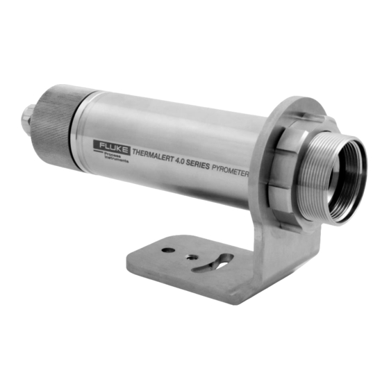
Sign In
Upload
Manuals
Brands
Fluke Manuals
Accessories
Thermalert 4.0 Series
Fluke Thermalert 4.0 Series Manuals
Manuals and User Guides for Fluke Thermalert 4.0 Series. We have
1
Fluke Thermalert 4.0 Series manual available for free PDF download: User Manual
Fluke Thermalert 4.0 Series User Manual (135 pages)
Smart Integrated Infrared Sensors
Brand:
Fluke
| Category:
Accessories
| Size: 5.11 MB
Table of Contents
Table of Contents
2
Table of Contents
3
List of Tables
8
List of Figures
8
Compliance Statement
11
Safety Information
12
Contacts
15
1 Description
16
Figure 1-1: Available Models
17
2 Technical Data
18
Measurement Specification
18
Optical Specifications
21
Electrical Specifications
23
Model 2-Wire
23
Model HART, 2-Wire
23
Model Fieldbus, 4-Wire
23
Model 6-Wire
24
Model 12-Wire
24
Environmental Specifications
25
Dimensions
26
Model 2-Wire / 6-Wire
26
Model Fieldbus, 4-Wire
26
Figure 2-1: Dimensions for the 2-Wire and 6-Wire Model
26
Figure 2-2: Dimensions for the 4-Wire Model, Fieldbus
26
Model 12-Wire
27
Figure 2-3: Dimensions for the 12-Wire Model
27
Scope of Delivery
28
3 Basics
29
Measurement of Infrared Temperature
29
Emissivity of Target Object
29
4 Environment
30
Ambient Temperature
30
Atmospheric Quality
30
Electrical Interference
30
Figure 4-1: One Earth Ground at the Sensor (Left) or at the Power Supply (Right)
30
Figure 4-2: Principle of the Galvanic Isolation for the 6-Wire Model
31
Figure 4-3: Principle of the Galvanic Isolation for the 12-Wire Model
31
5 Installation
32
Positioning
32
Distance to Object
32
Figure 5-1: Proper Sensor Placement
32
Viewing Angles
33
Figure 5-2: Acceptable Sensor Viewing Angles
33
Model 2-Wire
34
Back Panel
34
Table 5-1: Terminal Connections
34
Table 5-2: Test Modes
34
Figure 5-3: Rear Panel for 2-Wire Sensor and Emissivity Preset at 0.95
34
Cable Connection
35
Ma Single Loop
37
Figure 5-4: Principle Circuit Diagram: Infrared Sensor with Multiple Loads
38
Figure 5-5: Equivalent Circuit Diagram: Infrared Sensor with Multiple Loads
38
Ma Multiple Loops
39
Table 5-3: Power Supply Requirements for Multiple Loads
39
Alarm Output al
40
Figure 5-6: Principle Circuit Diagram: Infrared Sensor with Multiple Loads
40
Figure 5-7: Exemplary Wiring the Alarm Output al for the 2-Wire Sensor
40
Model HART, 2-Wire
41
Back Panel
41
Cable Connection
41
Ma Loop
41
Alarm Output al
41
Table 5-4: Terminal Connections
41
Figure 5-8: Rear Panel for the HART 2-Wire Model
41
Model Fieldbus, 4-Wire
42
Wiring
42
Sensor Address
42
Advanced Addressing
42
Figure 5-9: M12 Connector Socket and Pin Assignment
42
Figure 5-10: Sensor Connection to a PC Using Poe
42
Reset Addressing
43
PC Network Adapter
43
Figure 5-11: Command Prompt Window
43
ASCII Programming
45
Http Server
45
Model 6-Wire
45
Back Panel
45
Figure 5-12: Rear Panel for 6-Wire Sensor
45
Cable Connection
46
Terminal Strip
46
Analog out
46
Ma Output
46
Output
46
Table 5-5: Pin Assignment for Terminal Strip
46
Figure 5-13: Wiring Analog out as Current Output
46
TC Output
47
RS485 Communication
47
Model 12-Wire
47
Back Panel
47
Table 5-6: Pin Assignment for DIN Connector
47
Figure 5-14: Wiring Analog out as Voltage Output
47
Figure 5-15: DIN Connector Pin Layout (Pin Side)
47
FTC1 - Emissivity Setting
48
FTC2 - Background Temperature Compensation
48
Table 5-7: Ratio between Analog Input Voltage and Emissivity (Example)
48
Figure 5-16: Adjustment of Emissivity at FTC1 Input (Example)
48
Trigger Input
49
Figure 5-17: Principle of Background Temperature Compensation
49
Figure 5-18: Adjustment of Background Temperature Compensation at FTC2 Input (Example)
49
Figure 5-19: Wiring the Trigger Input
50
Figure 5-20: Resetting the Peak Hold Function
50
Figure 5-21: Holding the Output Temperature
50
Hold
50
Reset
50
Laser
51
Relay Output
51
Analog out
51
Ma Output
51
Figure 5-22: Spike Voltage Limitation for the Alarm Relay
51
Figure 5-23: Wiring Analog out as Current Output
51
Output
52
Figure 5-24: Wiring Analog out as Voltage Output
52
Model LTD-04
53
Assembly
53
Figure 5-25: Assembly of the Air Purge
53
6 Operation
54
Figure 6-1: Laser Indication
54
Figure 6-2: Averaging
55
Figure 6-3: Peak Hold
55
Figure 6-4: Valley Hold
56
Figure 6-5: Advanced Peak Hold
56
Figure 6-6: Advanced Peak Hold with Averaging
57
Figure 7-1: Network in Linear Topology (Daisy Chain)
58
Figure 7-2: RS485 Communication for 6-Wire Model
59
Figure 7-3: RS485 Communication for 12-Wire Model
59
Figure 7-4: Wiring the Sensor's RS485 Interface with USB/RS485 Converter in 2-Wire Mode
60
Figure 7-5: Wiring the Multiple Sensors Via RS485 Interface with USB/RS485 Converter in 2-Wire Mode
60
Table 8-1: Pyrometer Parameters
63
Table 8-2: Messages
63
Table 8-3: Input Data
63
Table 8-4: Output Data
63
Table 8-5: Parameter Types
64
Table 8-6: Error Codes
64
Table 9-1: Pyrometer Parameters
65
Table 9-2: Input Data
66
Table 9-3: Output Data
66
Table 9-4: Parameter Types
66
Table 9-5: Error Codes
67
Table 10-1: Sensor Information
69
Table 10-2: Overview to Temperature Hold Functions
71
Figure 11-1: Typical Installation with HART Adapter
73
Figure 12-1: Intrinsic Safety Installation with Power Supply Barrier from Company Pepperl+Fuchs (Example)
75
Table 13-1: Cable Specification
77
Table 13-2: Color Assignment to DIN Connector
77
Figure 13-1: 12-Wire Cable, High Temp Version
77
Table 13-3: Cable Specification
79
Table 13-4: Color Assignment to DIN Connector
79
Figure 13-2: 12-Wire Cable, Low Temp Version
79
Table 13-5: Available Ethernet Poe Cables
81
Figure 13-3: Ethernet Poe Cable
81
Figure 13-4: Pin Assignment (Front View)
81
Figure 13-5: Terminal Block with Wire Color Assignment
82
Figure 13-6: Terminal Block in an Enclosure
83
Figure 13-7: Industrial Power Supply
84
Figure 13-8: Power Supply with Terminal Box
85
Figure 13-9: USB/RS485 Converter
87
Figure 13-10: Poe Injector
88
Figure 13-11: Overview to Mechanical Accessories
89
Figure 13-12: Mounting Nut
90
Figure 13-13: Fixed Bracket
91
Figure 13-14: Adjustable Bracket
92
Figure 13-15: Swivel Bracket
93
Figure 13-16: Installation of the Sighting Tube
94
Figure 13-17: Dimensions for the Sighting Tube
94
Figure 13-18: Available Sighting Tubes
95
Figure 13-19: Pipe Adapter
96
Table 13-6: Protective Windows
97
Figure 13-20: Protective Window
97
Figure 13-21: Right Angle Mirror
98
Figure 13-22: Air Purge
99
Figure 13-23: Air/Water-Cooled Housing
100
Table 13-7: Minimum Device Temperatures [°C/°F]
102
Figure 13-24: Thread Adapter
103
Figure 13-25: Mounting Flange
104
Table 14-1: Troubleshooting
105
Table 14-2: Error Codes for Outputs
105
Table 14-3: Error Codes Via Digital Communication
105
Figure 15-1: Optical Diagrams LT-07 Models
107
Figure 15-2: Optical Diagrams LT-15 Models
107
Figure 15-3: Optical Diagrams LT-30 Models
108
Figure 15-4: Optical Diagrams LTB-30 Models
109
Figure 15-5: Optical Diagrams LT-50 Models
110
Figure 15-6: Optical Diagrams LT-70 Models
111
Figure 15-7: Optical Diagrams LTD-04 Models
111
Figure 15-8: Optical Diagrams P7-30 Models
112
Figure 15-9: Optical Diagrams G7-70 Models
112
Figure 15-10: Optical Diagrams G5-30 Models
112
Figure 15-11: Optical Diagrams G5-70 Models
113
Figure 15-12: Optical Diagrams MT-30 Models
114
Figure 15-13: Optical Diagrams MT-70 Models
115
Figure 15-14: Optical Diagrams P3-20 Models
116
Figure 15-15: Optical Diagrams HT-60 Models
117
Figure 15-16: Optical Diagrams 1M-150 Models
118
Figure 15-17: Optical Diagrams 2M-150 Models
119
Figure 15-18: Optical Diagrams 3M-150 Models
120
Figure 15-19: Spot Size Calculator
121
Advertisement
Advertisement
Related Products
Fluke T5-1000
Fluke T5-600
Fluke T40-LT-15-SF0-0
Fluke Thermal Imagers TiR
Fluke ThermoView Series
Fluke ThermoJacket
Fluke TB2020
Fluke TB4938
Fluke TB4012
Fluke TAP-100-2X16
Fluke Categories
Measuring Instruments
Test Equipment
Multimeter
Thermometer
Laboratory Equipment
More Fluke Manuals
Login
Sign In
OR
Sign in with Facebook
Sign in with Google
Upload manual
Upload from disk
Upload from URL