Advertisement
Quick Links
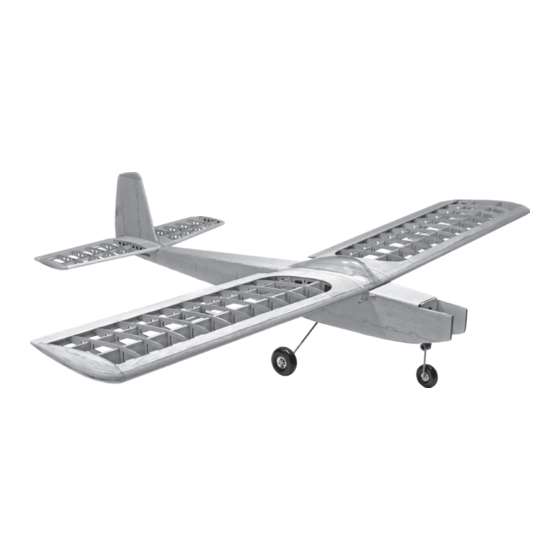
Specifications:
Wingspan: 56 in.
Wing Area: 560 sq in.
Airframe Length: 41.5 in.
Weight: 3.5 - 4.5 lb.
Using the Manual
Be sure to read each step thoroughly before you start
the step. Test-fit the parts together to make sure they
fit properly. If necessary trim to fit.
Beside each step you will notice a check box (or two).
These are so you can keep track of your progress
while building your kit. For steps that have two boxes,
as in the construction of the left and right wing halves,
these steps must be performed two times.
• Your Old School Model Works aircraft should not be
considered a toy, but rather a sophisticated, working
model that functions very much like a full-size airplane.
Because of its performance capabilities, this model, if not
assembled and operated correctly, could possibly cause
injury to yourself or spectators, and damage to property.
• You must assemble this model according to the
instructions. Do not alter or modify this model, as doing
so may result in an unsafe or un-flyable model. In a few
cases the instructions may differ slightly from the photos.
In those instances the written instructions should be
considered as correct.
• You must take time to build straight, true and strong.
• You must use a R/C radio system that is in first-
class condition, a correctly sized power system and
components
(electronics,
throughout the building process.
• You must correctly install all R/C and other components
so that the model operates correctly on the ground
and in the air. (Installation shown in the manual is a
suggestion. You may have to adjust the mounting steps
to accommodate the size of your radio equipment.)
• You must check the operation of the model before every
flight to insure that all equipment is operating and that
the model has remained structurally sound. Be sure to
check clevises or other connectors often and replace
them if they show any signs of wear or fatigue.
batteries,
wheels,
etc.)
• If you are not an experienced pilot or have not flown this
type of model before, we recommend that you get the
assistance of an experienced pilot in your R/C club for
your first flights. If you're not a member of a club, your
local hobby shop has information about clubs in your
area whose membership includes experienced pilots.
• While this kit has been flight tested to exceed normal
use, if this model will be used for extremely high stress
flying, such as racing, or if a power system larger than
one in the recommended range is used, the modeler is
responsible for taking steps to reinforce the high stress
points and/or substituting hardware more suitable for the
increased stress.
Remember: Take your time and follow
the instructions to end up with a well-
built model that is straight and true.
www.oldschoolmodels.com
Advertisement

Subscribe to Our Youtube Channel
Related Manuals for Old School Model Works FIFTY SIX


Summary of Contents for Old School Model Works FIFTY SIX
- Page 1 • Your Old School Model Works aircraft should not be considered a toy, but rather a sophisticated, working • If you are not an experienced pilot or have not flown this model that functions very much like a full-size airplane.
-
Page 2: Included Items
WARNING • Inspect your model before every flight to ensure it is airworthy. • Be aware of any other radio frequency user who may present an interference problem. READ THROUGH THIS MANUAL • Always be courteous and respectful of other users in your selected flight area. - Page 3 You’ll need a flat building surface that is a minimum of Although an easy to build kit, our Fifty Six kit is not for the novice 36” long. Position the port builder. We are assuming the builder is used to constructing balsa wing plan over the surface and kits and has the techniques and skills necessary to do so.
- Page 4 triple, and quadruple check that you have them in the correct n n Step 3 - Wing Assembly (front spar) order, then when satisfied, push the front spar into the larger Locate another SP2 from BP1 rectangular hole in each rib. The rear spar is pushed through the and this is now glued on top of smaller rectangular hole towards the rear of the ribs.
- Page 5 place between the two “fingers/fangs/points” on the back of each n n Step 13 - Wing Assembly (R3 ribs) rib. Working from one side to the other, glue the trailing edge to With the SPACERs in place, carefully align both R3 ribs and the each of the ribs, making sure that the alignment of each rib is still outermost R2 rib, then tack them in place to the spars (best to tack spot on.
- Page 6 When cured, you’ll now have a single, longer piece of sheeting. Also note that CS4 has a pre-cut hole in it. This is to allow the aileron servo wire to exit. This hole should be positioned so it’s closer to the root rib (R1).
- Page 7 Glue Note - if you prefer to make your Fifty Six a 3-channel system these, centered across the two R5 ribs as shown on the plans. (without ailerons), you can glue these strips to the trailing edge of each wing to continue on the airfoil shape of the wing.
- Page 8 the stab, then the other. Take the time to make sure everything Step 48 - Stab Assembly (ST) is aligned properly BEFORE you glue it in place, as it’s just about Sand the both ends of the stab assembly so impossible to fix if things are out of order and glued in place.
- Page 9 Step 54 - Fuse Assembly (F1/F2) Step 59 - Fuse Assembly (SS) Locate F1 from LP2 and F2 from LP4. These are Locate both SS from LP3. These glued together as shown to form the firewall. are the inner supports for the Make sure F1 is aligned with F2 and that the wing saddle.
- Page 10 cut the bottom strip first. It will start just at the outline you made, these two pieces, as it should rearwards and stop right at the start of TW1 (refer to the plans be inserted into the cutout at for these locations). The top strip starts at the drawn outline, and the front of BS.
- Page 11 fuselage, making sure the grain is cross-ways. Mark, cut and glue a from the flat of the building board to tips of the trailing edges, they portion of the sheeting in position. Repeating this technique, work should be the same distance your way forward until you almost reach F1.
- Page 12 Step 87 - Electric firewall (E1) to place - firmly seated and at the correct angle. If (and only if) you are powering your Fifty Six with an electric power Step 84 - Sanding system, you’ll need to also install...
- Page 13 Step 91 - Electric firewall (optional top sheeting) our prototype is an O.S .30 mounted on a Dave Brown Products If (and only if) you are powering your Fifty Six with an electric power engine mount (now available from Ohio Superstar as of the time system, you may want to add additional sheeting to cover the area this manual was written).
- Page 14 Included is a canopy and though it's certainly up to you if you tray by using a bit of self-adhesive hook-and-loop (not included). choose to use it, the canopy is just a defining part of the Fifty Six's' The radio's switch should be mounted to the opposite side outline, so why not use it? of the muffler (to help keep the goop out of it).
- Page 15 CAUTION! DO NOT SKIP THIS STEP! collapsed. Turn on the radio in your airplane, but do not attach the The recommended Center of Gravity (CG) range for the Fifty Six is arming switch. 3-3/4"- 3-7/8" from the leading edge of the wing, and you’ll see With your airplane on the ground, you should be able to walk 30 this marked on the fuselage plan with this symbol.
- Page 16 APPENDIX A Page 16 www.oldschoolmodels.com Construction Manual...
- Page 17 APPENDIX A APPENDIX A Construction Manual www.oldschoolmodels.com Page 17...
- Page 18 For more information on all of our other products, as well as the latest news from Old School Model Works: Please check out out website: www.oldschoolmodels.com You can reach us on Facebook: www.facebook.com/oldschoolmodelworks...
Need help?
Do you have a question about the FIFTY SIX and is the answer not in the manual?
Questions and answers