Advertisement
Quick Links
Using the Manual
Be sure to read each step thoroughly before
you start the step. Test-fit the parts together
to make sure they fit properly. If necessary
trim to fit.
Beside each step you will notice a check
box (or two). These are so you can keep
track of your progress while building your
kit. For steps that have two boxes, as in the
construction of the left and right wing halves,
these steps must be performed two times.
• Your Old School Model Works aircraft should not be
considered a toy, but rather a sophisticated, working
model that functions very much like a full-size airplane.
Because of its performance capabilities, this model, if not
assembled and operated correctly, could possibly cause
injury to yourself or spectators, and damage to property.
• You must assemble this model according to the
instructions. Do not alter or modify this model, as doing
so may result in an unsafe or un-flyable model. In a few
cases the instructions may differ slightly from the photos.
In those instances the written instructions should be
considered as correct.
• You must take time to build straight, true and strong.
• You must use a R/C radio system that is in first-
class condition, a correctly sized power system and
components
(electronics,
throughout the building process.
• You must correctly install all R/C and other components
so that the model operates correctly on the ground
and in the air. (Installation shown in the manual is a
suggestion. You may have to adjust the mounting steps
to accommodate the size of your radio equipment.)
• You must check the operation of the model before every
flight to insure that all equipment is operating and that
the model has remained structurally sound. Be sure to
check clevises or other connectors often and replace
them if they show any signs of wear or fatigue.
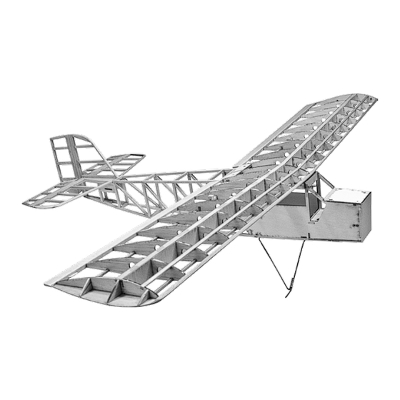
Specifications: Wingspan: 51 in. • Wing Area: 400 sq in.
Airframe Length: 33 in. • Weight: 3-3.5 lb.
batteries,
wheels,
etc.)
prototype built & flown
• If you are not an experienced pilot or have not flown this
type of model before, we recommend that you get the
assistance of an experienced pilot in your R/C club for
your first flights. If you're not a member of a club, your
local hobby shop has information about clubs in your
area whose membership includes experienced pilots.
• While this kit has been flight tested to exceed normal
use, if this model will be used for extremely high stress
flying, such as racing, or if a power system larger than
one in the recommended range is used, the modeler is
responsible for taking steps to reinforce the high stress
points and/or substituting hardware more suitable for the
increased stress.
Remember: Take your time and follow
the instructions to end up with a well-
built model that is straight and true.
www.oldschoolmodels.com
by dan gaston
Advertisement

Related Manuals for Old School Model Works Robin Hood 25


Summary of Contents for Old School Model Works Robin Hood 25
- Page 1 • If you are not an experienced pilot or have not flown this type of model before, we recommend that you get the • Your Old School Model Works aircraft should not be assistance of an experienced pilot in your R/C club for considered a toy, but rather a sophisticated, working your first flights.
-
Page 2: Included Items
WARNING We urge you to join the AMA (Academy of Model Aeronautics) and a local R/C club. The AMA is the governing body of model aviation READ THROUGH THIS MANUAL and membership is required to fly at AMA clubs. Though joining the AMA provides many benefits, one of the BEFORE STARTING CONSTRUCTION. -
Page 3: Before Starting Assembly
• Pencil or pen Let’s begin construction by working on the left (port) wing of your Robinhood 25. • Ruler • String (18” length) Prepare your work area • T-Pins • Waxed paper You’ll need a flat building surface that is a minimum of 36” long. •... - Page 4 Step 6 - Wing Assembly (attach R6) Step 12 - Wing Assembly Position the R6/R7 assembly in position. Make sure it is vertical and (attach R3) pin the rear tab to the building board. Do not glue yet. Locate one R3 rib from BP3 and two WB2 sheer webs from BP4.
- Page 5 gap between the R5 ribs, with the TC towards the inside of the Step 18 - Wing Assembly (cut trailing edge) wing. Also add glue it to where SMR touches the lower sub-spar Measure and cut one of the for a bit of extra support. 5/16”...
- Page 6 of some 30 minute epoxy. Remove the DH2 and DH1 parts, then Step 30 - Wing Assembly (center sheeting) mix up enough 30 minute epoxy to Carefully spread a thin layer of Now the center sheeting epoxy on the inside of the dihedral box of one wing half, and both applied sides of one half of DH1.
- Page 7 and WH4 from the LP4 sheet. Also, cut a 1-1/4” length from the through the wood. Instead, included 1/4” dowel and round off one of the dowel’s ends. use a few pins around the These pieces all interlock together so we suggest dry fitting these outside of FRS as shown in components the first time.
- Page 8 Step 44 - Fuselage Assembly (prepare for left side build) Step 49 - Fuselage Assembly (stab support) As mentioned before, Measure and cut the horizontal support for the stab from 1/4” the left side is built on square strip. Pin in position and glue into place. top of the right side Step 50 - Fuselage Assembly (diagonal supports) you’ve just assembled.
- Page 9 slots on FRS. TF must fit flush with the fuselage side, and former Step 61 - Fuselage Assembly (attach H2 or H2A) F3. When satisfied with the location and fit of TF, glue TF to FRS, Now is the time to make a choice. Will you hold on the front hatch but not to F3 at this time.
- Page 10 equal amounts of balsa on the insides of Step 65 - Fuselage Assembly (LG5, LG6) both sides. 1 inch Locate LG5 and LG6 Using a ruler and straight-edge, measure from sheet LP2. LG5 is and draw the guides as shown in the glued to LG4, between photo (1/2 way on the verticals, tapering the bottom longerons...
- Page 11 WH9 then lays on top of Step 81 - Stab/Elevator (S2 installs) WH8. Each of these pieces Take one of the S2 assemblies, position and glue it in place on the should be epoxied in position left tip of the stab. Then do the same with the other S2 on the right for maximum strength.
- Page 12 Step 89 - Stab/Elevator (finished) Step 98 - Rudder (RD3 & RD4 install) Once the glue has set, remove the finished elevator from the plans. Take the RD3 and RD4 assemblies, position and glue them into position. Prepare your work area Step 99 - Rudder (trailing edges) Position the fuselage side plan over the surface and tape into position.
- Page 13 Carefully sand this to match, test fitting along the way. Step 106 - Fuselage Assembly (level stab) When satisfied with the fit, place the hatch over a small piece of To attach the stab, wax paper, making sure that is upside down. Glue one H3 in each first bolt the wing of the two slots on the rear of the hatch, making sure that the H3 in place.
- Page 14 flux over the entire wire-wrap, then use a small torch (or a soldering Step 112 - Hinge the rudder iron) to securely older the wire wrap in position, securing the front Make the necessary slots/holes needed to hinge the rudder to the and rear landing gear wires into a solid, one piece unit.
- Page 15 Contact Callie Graphics at this link: https://callie-graphics.com or scan the QR code on the previous page. Note that Callie Graphics is not affiliated with Old School Model Works, nor does Old School Model Works generate any income from this partnership. Step 122 - Attach the Control Surfaces Now is the time to attach all the control surfaces to the airframe, by gluing the hinges in position.
- Page 16 Recommended Control Throws: In that Old School Model Works has no control over the final The amount of control throw should be adjusted as closely as assembly or material used for the final assembly, no liability shall be...
- Page 17 APPENDIX A Construction Manual www.oldschoolmodels.com Page 17...
- Page 18 Page 18 www.oldschoolmodels.com Construction Manual...
Need help?
Do you have a question about the Robin Hood 25 and is the answer not in the manual?
Questions and answers