Advertisement
Quick Links
Using the Manual
Be sure to read each step thoroughly before you start
the step. Test-fi t the parts together to make sure they
fi t properly. If necessary trim to fi t.
Beside each step you will notice a check box (or two).
These are so you can keep track of your progress
while building your kit. For steps that have two boxes,
as in the construction of the left and right wing halves,
these steps must be performed two times.
• Your Old School Model Works aircraft should not be
considered a toy, but rather a sophisticated, working
model that functions very much like a full-size airplane.
Because of its performance capabilities, this model, if not
assembled and operated correctly, could possibly cause
injury to yourself or spectators, and damage to property.
• You must assemble this model according to the
instructions. Do not alter or modify this model, as doing
so may result in an unsafe or un-fl yable model. In a few
cases the instructions may differ slightly from the photos.
In those instances the written instructions should be
considered as correct.
• You must take time to build straight, true and strong.
• You must use a R/C radio system that is in fi rst-
class condition, a correctly sized power system and
components
(electronics,
throughout the building process.
• You must correctly install all R/C and other components
so that the model operates correctly on the ground
and in the air. (Installation shown in the manual is a
suggestion. You may have to adjust the mounting steps
to accommodate the size of your radio equipment.)
• You must check the operation of the model before every
fl ight to insure that all equipment is operating and that
the model has remained structurally sound. Be sure to
check clevises or other connectors often and replace
them if they show any signs of wear or fatigue.
batteries,
wheels,
etc.)
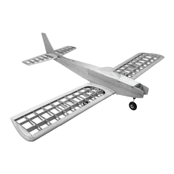
Specifi cations:
Wingspan: 56 in.
Wing Area: 560 sq in.
Airframe Length: 42.5 in.
Weight: 3.75 - 4.5 lb.
• If you are not an experienced pilot or have not fl own this
type of model before, we recommend that you get the
assistance of an experienced pilot in your R/C club for
your fi rst fl ights. If you're not a member of a club, your
local hobby shop has information about clubs in your
area whose membership includes experienced pilots.
• While this kit has been fl ight tested to exceed normal
use, if this model will be used for extremely high stress
fl ying, such as racing, or if a power system larger than
one in the recommended range is used, the modeler is
responsible for taking steps to reinforce the high stress
points and/or substituting hardware more suitable for the
increased stress.
Remember: Take your time and follow
the instructions to end up with a well-
built model that is straight and true.
www.oldschoolmodels.com
Advertisement

Subscribe to Our Youtube Channel
Related Manuals for Old School Model Works Lark


Summary of Contents for Old School Model Works Lark
- Page 1 • Your Old School Model Works aircraft should not be considered a toy, but rather a sophisticated, working • If you are not an experienced pilot or have not fl own this model that functions very much like a full-size airplane.
-
Page 2: Included Items
WARNING • Inspect your model before every fl ight to ensure it is airworthy. • Be aware of any other radio frequency user who may present an interference problem. READ THROUGH THIS MANUAL • Always be courteous and respectful of other users in your selected fl ight area. - Page 3 36” long. Position the starboard wing Although an easy to build kit, our Lark kit is not for the novice plan over the surface and tape builder. We are assuming the builder is used to constructing balsa into position.
- Page 4 (towards the wing root). When glued in place, R2A and R4A need to n n Step 3 - Wing Assembly (front spar) be perfectly aligned with top and bottom edges of their respective Locate another SP2 from BP1 ribs. Also the rear edge should be just on the edges of R2A and and this is now glued on top of R4A should be aligned with the rear spar cutouts in each rib.
- Page 5 have any extra glue fouling the holes where the dihedral braces n n Step 13 - Wing Assembly (SPACER) will slide into. Locate SPACERs from LP1. These are just as the name implies - n n Step 19 - Wing Assembly (R1A) simply spacers and should NOT Locate two of the R1A pieces from be glued into the airframe at any...
- Page 6 helps). CS3 has purposely been cut assembly from the board. Once removed, flip it over and it’s time a little long, so you'll need to trim to remove all the underside tabs that helped hold the ribs in place. it to get a perfect fit filling the gap There’s one in the front and one in the back of each rib.
- Page 7 spars. With the wing half laid on it’s top, glue these two strips to n n Step 31 - Wing Assembly (LE & TE) the R6 ribs as shown on the plans. These strips should be flush with Locate one LE and one TE from BP14. These are the lower leading the lower-most pre-cut edges of the R6 ribs.
- Page 8 Step 50 - Vertical Fin Assembly (VF15) Note - if you prefer to make your Lark a 3-channel system (without ailerons), you can glue these strips to the trailing edge of each wing Remove the pins from the vertical structure and to continue on the airfoil shape of the wing.
- Page 9 Step 58 - Vertical Fin Assembly (VF16) Step 63 - Stab Assembly (leading edges) Remove the rudder assembly and flip it over. Again, lightly sand Locate the other length of the structure so it's flat. 1/4” x 1/2” balsa strip to Then locate the other VF17 from BP17 and glue this in place over use as the leading edge of the front of the structure making sure it's perfectly aligned.
- Page 10 Step 68 - Elevator Assembly Step 74 - Fuse Assembly (F4, WH5) Locate the two extra pieces of 5/16” x 1-1/4” tapered edge stock, Locate F4 from LP2 and the WH5 as well as the length of 3/16” dowel. Cut the dowel to length, as assembly you made earlier.
- Page 11 these four mounting positions into F1. Step 83 - Fuse Assembly (fuse sides) Then use the 4 screws and t-nuts to fasten this in position. You might want Take both fuselage sides and align to use a bit of thread lock and cut away the extra length from interfering them.
- Page 12 You'll need to remove any pins/tape holding the rear of the leading edges are nicely rounded, and you might want to test fit fuselage together for the next few steps. them to the rear of the fuselage a few times as you sand, to get an idea of where you might need a bit more shaping.
- Page 13 sheeting between Step 95 - Fuse Assembly (TS2) F2. This you will need to cut Locate TS2 from BP5. As yourself from 3/32" sheeting you've done before, test fit scrap (plenty to choose from the this in place making sure all various BP sheets).
- Page 14 If you're using a glow engine to power your Lark, it is strongly spinner, we ended up cutting about 1/2" off the length of each E1. Your recommended that you fuel proof the inside of the battery mileage may vary, so do your homework before mounting these in place.
- Page 15 Although you can install the servos and control hardware after covering screw made a mark, then re-attach. Use a touch of thread-locking your Lark, we find it easier to temporarily mount everything in place compound on the screw to make sure it doesn't vibrate loose later before covering.
- Page 16 Covering included) on the axles. For a maintenance free installation, file Now it is time to cover the Lark. Remove the powerplant, main a small flat on the axle where the set screw of the wheel collar gear, nosewheel assembly, pushrods, and any other components touches.
- Page 17 Warranty Information for this purpose. Old School Model Works guarantees this kit to be free from defects in both We recommend balancing it at the material and workmanship at the date of purchase. This warranty does not cover forward point for the first flights, then moving it backward if you'd any parts damage by use or modification.
- Page 18 Page 18 www.oldschoolmodels.com Construction Manual...
- Page 19 Construction Manual www.oldschoolmodels.com Page 19...
- Page 20 Page 20 www.oldschoolmodels.com Construction Manual...
Need help?
Do you have a question about the Lark and is the answer not in the manual?
Questions and answers