Advertisement
Quick Links
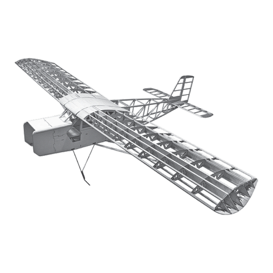
Specifications: Wingspan: 80 in. • Wing Area: 1120 sq in.
Airframe Length: 58 in. • Weight: 4.5 lbs. (framed), 8-10 lbs.(rtf)
Using the Manual
Be sure to read each step thoroughly before
you start the step. Test-fit the parts together
to make sure they fit properly. If necessary
trim to fit.
Beside each step you will notice a check
box (or two). These are so you can keep
track of your progress while building your
kit. For steps that have two boxes, as in the
construction of the left and right wing halves,
these steps must be performed two times.
• Your Old School Model Works aircraft should not be
considered a toy, but rather a sophisticated, working
model that functions very much like a full-size airplane.
Because of its performance capabilities, this model, if not
assembled and operated correctly, could possibly cause
injury to yourself or spectators, and damage to property.
• You must assemble this model according to the
instructions. Do not alter or modify this model, as doing
so may result in an unsafe or un-flyable model. In a few
cases the instructions may differ slightly from the photos.
In those instances the written instructions should be
considered as correct.
• You must take time to build straight, true and strong.
• You must use a R/C radio system that is in first-
class condition, a correctly sized power system and
components
(electronics,
throughout the building process.
• You must correctly install all R/C and other components
so that the model operates correctly on the ground
and in the air. (Installation shown in the manual is a
suggestion. You may have to adjust the mounting steps
to accommodate the size of your radio equipment.)
• You must check the operation of the model before every
flight to insure that all equipment is operating and that
the model has remained structurally sound. Be sure to
check clevises or other connectors often and replace
them if they show any signs of wear or fatigue.
batteries,
wheels,
etc.)
• If you are not an experienced pilot or have not flown this
type of model before, we recommend that you get the
assistance of an experienced pilot in your R/C club for
your first flights. If you're not a member of a club, your
local hobby shop has information about clubs in your
area whose membership includes experienced pilots.
• While this kit has been flight tested to exceed normal
use, if this model will be used for extremely high stress
flying, such as racing, or if a power system larger than
one in the recommended range is used, the modeler is
responsible for taking steps to reinforce the high stress
points and/or substituting hardware more suitable for the
increased stress.
Remember: Take your time and follow
the instructions to end up with a well-
built model that is straight and true.
www.oldschoolmodels.com
Advertisement

Related Manuals for Old School Model Works Robin Hood 80


Summary of Contents for Old School Model Works Robin Hood 80
-
Page 1: Using The Manual
• If you are not an experienced pilot or have not flown this type of model before, we recommend that you get the • Your Old School Model Works aircraft should not be assistance of an experienced pilot in your R/C club for considered a toy, but rather a sophisticated, working your first flights. -
Page 2: Included Items
WARNING We urge you to join the AMA (Academy of Model Aeronautics) and a local R/C club. The AMA is the governing body of model aviation and membership is required to fly at AMA clubs. READ THROUGH THIS MANUAL Though joining the AMA provides many benefits, one of the primary reasons to join is liability protection. -
Page 3: Before Starting Assembly
• Engine/Motor mount and mounting hardware Closely inspect the supplied laser cut parts for damage. If you find • Receiver - (4 channel minimum) any damaged or missing parts, contact us immediately. • 5 standard sized servos (4 if electric) Online Supplementary Photos •... - Page 4 board, then fit the WF3 Step 3 - Lower spar and WB3 sheer webs in Locate one of the 3/8” square place. When satisfied basswood strips. This will be with the fit and location, the lower spar. Position over glue these pieces in the plan, measure the length place.
- Page 5 WF3 and WB3 in place Step 17 - Wing Assembly (upper spar) before moving on to This next part takes a bit of time, the second. so we recommend against using For the third R5, the an instant setting glue. If you are WB2 is used as the front using CA, use a thicker formulation sheer web.
- Page 6 Step 21 - Wing Assembly (aileron leading edge) Step 25 - Wing Assembly (gussets) Locate remaining 1/4” Along the leading and trailing x 1” balsa strip from edges, there are number of G1 the previous step as gussets to be glued in place. it now becomes the These gussets can be found leading edge of the...
- Page 7 Switch to a finer grit (150-200) to smooth Step 29 - Wing Assembly (lower rear sub-spar) out the entire wing. Locate one 1/4” square balsa stick. This is used as the lower rear sub-spar. Using the same Sand excess technique you did the in past trailing edge stock.
- Page 8 left (port) wing plan. Now go back to step 3 and repeat the steps In each case, make sure halves are perfectly aligned when gluing to build the port wing. together. Be very careful to make sure you make a mirror image of the wing Step 42 - Fuselage Assembly (stab supports) tip - not another right tip.
- Page 9 Once the glue has cured, do the same with F6 positioning it in the Step 53 - Fuselage Assembly (bottom cross brace) rear slots of TRAY. Cut the bottom cross brace from some of the leftover 3/8” square basswood stock. Glue it in Step 48 - Fuselage Assembly (TRAY assembly) position as shown, underneath F6.
- Page 10 Step 58 - Fuselage Assembly (fuselage corners) Step 63 - Fuselage Assembly (F7 cross brace) Locate the 1/2” square Using 3/16” 3/8” balsa stick. Then measure basswood, measure and and cut the upper and cut the cross brace to lower corners of the front strengthen the top of F7.
- Page 11 Step 68 - Fuselage Assembly (P7) Step 74 - Fuselage Assembly (dihedral brace & cross braces) Locate both P7s from BP7. Glue Now it’s time to glue the them together to create a thicker dihedral brace into the large P7 as shown here. slots of the R0 ribs and fuse sides.
- Page 12 Step 80 - Fuselage Assembly (front hatch) Step 85 - Fuselage Assembly (F1) Locate C3 from LP10. Sand Locate F1. It is the 1/4” piece of aircraft a bevel on the three front ply, separate from the rest of the wood edges as shown here.
- Page 13 Step 89 - Fuselage Assembly (P2) Step 94 - Elevator (leading edge) Glue the P2 assembly in The two S3 and two S4 place on the underside of the assemblies should be pinned fuselage as shown. in place. Measure two lengths of 1/4 x 1/2”...
- Page 14 Step 100 - Tail surfaces (sanding) Step 105 - Fuselage Assembly (attach stab) Once the glue has set, remove the finished vertical fin and rudder Mix up a little bit of epoxy and glue the stab to the fuselage, from the plans. Now take the time to sand the horizontal stabilizer, making sure to align it up to the marks you made earlier.
- Page 15 to one side than the other. The strap should be positioned so the gear wires into a solid, one piece unit. end with the 2 closer holes is inside the fuselage, and the other When finished, do the same to the other side of the gear and you end protruding from the fuse side by a 1/4”...
- Page 16 similar posts from the remaining pieces, sanding the ends flat. good, final sanding. Make sure everything is flush and smooth, that Position the aileron servo on the bottom of the aileron servo covers the wings are airfoil shaped along their entire width and everything so the servo arm output shaft is centered in the opening.
- Page 17 Note that Callie Graphics is not affiliated with Old School Model for the throttle pushrod, Works, nor does Old School Model Works generate any income fuel lines (and ignition from this partnership. pickup wire if gas) to pass through into the fuselage.
- Page 18 By moving the position of the clevis at the control horn toward In that Old School Model Works has no control over the final the outermost hole, you will decrease the amount of control throw of the control surface.
- Page 19 APPENDIX A Construction Manual www.oldschoolmodels.com Page 19...
- Page 20 APPENDIX A Page 20 www.oldschoolmodels.com Construction Manual...
- Page 21 APPENDIX A Construction Manual www.oldschoolmodels.com Page 21...
- Page 22 Page 22 www.oldschoolmodels.com Construction Manual...
Need help?
Do you have a question about the Robin Hood 80 and is the answer not in the manual?
Questions and answers