Table of Contents
Advertisement
Advertisement
Table of Contents

Related Manuals for Huvitz HOCT-1F/1


Summary of Contents for Huvitz HOCT-1F/1
- Page 1 OPTICAL COHERENCE TOMOGRAPHY HOCT-1F/1 SERVICE MANUAL...
- Page 2 HUVITZ reserves the right to make changes in its products or product specifications at any time and without prior notice, and is not required to update this documentation to reflect such changes.
-
Page 3: Table Of Contents
Optical Coherence Tomography HOCT-1F / 1------------------------------------------------------------------------------------- CONTENT 1. SAFETY PRECAUTIONS............................. 4 1.1 Overview ................................4 2. Symbol Information ..............................5 2.1 Usage Precautions ............................... 7 2.2 Environmental Considerations ........................... 10 2.3 Safety Precautions ............................. 12 3. INTRODUCTION ................................. 14 System Outline ..............................14 Intended Use .............................. - Page 4 -------------------------------------------------------------------------------------Optical Coherence Tomography HOCT-1F / 1 8. Exploded Diagram..............................59 8.1 COVER ASSY ..............................59 8.2 UNCOVER ASSY ............................... 60 8.3 BASE ASSY ................................ 61 8.4 PC BOX ASSY ..............................62 8.5 MOVING BASE ASSY ............................63 8.6 HEAD REST ASSY ............................. 64 8.7 LCD ASSY ................................
-
Page 5: Safety Precautions
Optical Coherence Tomography HOCT-1F / 1------------------------------------------------------------------------------------- 1. SAFETY PRECAUTIONS 1.1 Overview Safety is everyone’s responsibility. The safe use of this instrument is largely dependent upon the installers, users, operators, and managers. It is prerequisite to read and understand these specifications before installing, using, cleaning, fixing or revising. -
Page 6: Symbol Information
-------------------------------------------------------------------------------------Optical Coherence Tomography HOCT-1F / 1 2. Symbol Information The International Electro technical Commission (IEC) has established a set of symbols for medical electronic equipment which classify a connection or warn of any potential hazards. The classifications and symbols are shown below. - Page 7 Optical Coherence Tomography HOCT-1F / 1------------------------------------------------------------------------------------- CE for RoHS RoHS Directive Compliance 2011/65/EU WEEE indicating separate collection for electrical and electronic equipment...
-
Page 8: Usage Precautions
This instrument has been developed and tested according to safety standards as well as national and international standards. This guarantees a very high degree of safety for this device. HUVITZ is legally required to inform the users of all the information regarding safety. Observance of the instructions is the requirement for the safety. Therefore, please read carefully all instructions before switching on this instrument. - Page 9 Optical Coherence Tomography HOCT-1F / 1------------------------------------------------------------------------------------- CAUTION During the Anterior segment image operation, pull the joystick toward the operator before adjusting the alignment. Move the body to align patient’s eye. Move the body slowly while watching patient’s eye and body, because working distance is just 15mm that the front lens is very close to patient's eye.
- Page 10 -------------------------------------------------------------------------------------Optical Coherence Tomography HOCT-1F / 1 CAUTION The equipment is a Class I LED Product. The LED used for the equipment is safe under expected use conditions including situation such as looking into the LED using optical equipment. However, observe the following precautions when using the equipment ...
-
Page 11: Environmental Considerations
Where the instrument is exposed to chemical material or explosive gas. Be cautious so that things like dust and metal do not fall inside the instrument. Don’t disassemble or open the product. HUVITZ does not take responsibility for the possible problems... - Page 12 -------------------------------------------------------------------------------------Optical Coherence Tomography HOCT-1F / 1 Be careful not to block the fan of the instrument. Don’t plug the AC power cable into the outlet unless all parts of the instrument are completely connected. Otherwise, it will cause severe damage on the instrument. Pull out the power cable with holding the plug, not the cord.
-
Page 13: Safety Precautions
11. This instrument must be connected with the accessories supplied by HUVITZ. If you are to use other accessories, their safety or usability must be checked and proved by their manufacturers or HUVITZ. - Page 14 -------------------------------------------------------------------------------------Optical Coherence Tomography HOCT-1F / 1 16. Before you use, check the exterior of the instrument and its conditions. 17. Do not block any ventilation outlet necessary for proper heat dissipation. 18. If smoke, sparks or any abnormal noise or smell is noticed coming from the instrument, please switch the power off immediately and pull out the plug.
-
Page 15: Introduction
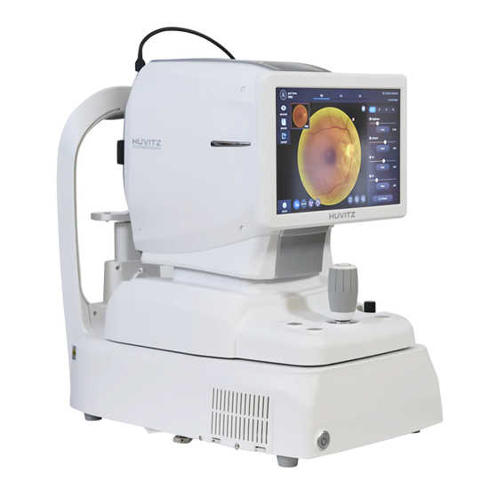
3. INTRODUCTION 3.1 System Outline The Huvitz Optical Coherence Tomography HOCT-1F, HOCT-1 is a non-contact, high-resolution tomographic and bio-microscopic imaging device. It is indicated for in-vivo viewing, axial cross-sectional and three dimensional imaging, color fundus imaging(HOCT-1F only) and measurement of posterior ocular structures, including the retina, retinal nerve fiber layer, ganglion cell plus inner plexiform layer, ganglion cell complex, macula, optic nerve head. -
Page 16: Operating Principles
-------------------------------------------------------------------------------------Optical Coherence Tomography HOCT-1F / 1 3.6 Operating Principles Fundus image 3.6.1 The anterior of an eye is illuminated by IR light, the posterior of an eye is illuminated by an infrared light and a white LED, of which lightings are emitted by the fundus illumination optical system. The fundus observation/photography optical system forms and makes an image with image sensors, which images are observed and manipulated with the display panel. -
Page 17: System Overview
Optical Coherence Tomography HOCT-1F / 1------------------------------------------------------------------------------------- 4. System Overview 4.1 Configuration and Functions ■ Front View Part Name Description Display Monitor for displaying captured image and user interface icon. Chinrest button Button for moving chinrest up and down. Joystick for aligning body to patient’s eye. Joystick Button for capturing image. - Page 18 -------------------------------------------------------------------------------------Optical Coherence Tomography HOCT-1F / 1 ■ Rear View...
- Page 19 Optical Coherence Tomography HOCT-1F / 1------------------------------------------------------------------------------------- Part Name Description Forehead rest Rubber for fix patient’s head. Headrest External LED External LED for fixing patient’s eyes. Chinrest For fixing patient’s chin. Lens for passing illumination light from body and Objective lens reflected light from patient’s eye.
-
Page 20: Optical System
-------------------------------------------------------------------------------------Optical Coherence Tomography HOCT-1F / 1 4.2 Optical System ⑫ ③ ⑤ ⑬ ④ ⑪ ⑨ ⑭ ⑩ ⑥ ② ⑧ ○ ⑦ ① ⑮ ○ ○ ○ ○ ○ ○ ○ ○ ○ ○ ○ ○ ⑥ ○ ○ ⑦... - Page 21 Optical Coherence Tomography HOCT-1F / 1------------------------------------------------------------------------------------- 4-2-1. List of Optical Components Patient’s Eye Objective Lens Cornea Mirror Cornea Lens Cornea Camera Scan mirror Return Mirror Hole Mirror W.D LED Fundus Diopter Lens Color Fundus Camera IR Fundus Camera IR Fundus Lens Color Fundus Lens Fundus Zoom Lens Fixation Mirror...
- Page 22 -------------------------------------------------------------------------------------Optical Coherence Tomography HOCT-1F / 1 4-2-2. Light Paths of the System A: Col or F undu s O bse rv ati on channel ○ ○ ○ ○ ○ ○ ○ (○ B: I R F undus O b serv at i on channel ...
-
Page 23: Electrical Construction Diagram
Optical Coherence Tomography HOCT-1F / 1------------------------------------------------------------------------------------- 4.3 Electrical construction diagram 4-3-1. Power input electrical block diagram ○ Power switch ON: DC5VSB(5V standby power) on ○ Po wer b ut t on on DC 12V on: sy st em powe r up... - Page 24 -------------------------------------------------------------------------------------Optical Coherence Tomography HOCT-1F / 1 4-3-2. System functional block diagram...
- Page 25 Optical Coherence Tomography HOCT-1F / 1------------------------------------------------------------------------------------- 4-3-3. Description of wire harness connection of Main Board/head optics...
- Page 26 -------------------------------------------------------------------------------------Optical Coherence Tomography HOCT-1F / 1 Connect Description (Connector number) Target connector HARNESS(MB(J1) TO AAM POWER(CN12)) AAM CN12 HARNESS(MB(J2) TO FUN CAM POWER) Color camera J4 HARNESS(MB(J4) TO TOUCH IF) Touch interface B/D HARNESS(MB(J5) TO BIF DATA) Base interface B/D CN5 HARNESS(MB(J6) TO AAM DATA) AAM B/D J4 HARNESS(MB(J7) TO FLASH LED)
- Page 27 Optical Coherence Tomography HOCT-1F / 1------------------------------------------------------------------------------------- 4-3-4. Description of wire harness connection of AAM board...
- Page 28 -------------------------------------------------------------------------------------Optical Coherence Tomography HOCT-1F / 1 Connect Description (Connector number) Target connector HARNESS(BIF TO X ENC PI) X encoder/PI HARNESS(BIF TO X ENC PI) X encoder/PI HARNESS(BIF TO Z ENC PI) Z encoder/PI HARNESS(BIF TO Z ENC PI) Z encoder/PI CN10 HARNESS(AAM(CN10) TO JOYSTICK) Joystick...
- Page 29 Optical Coherence Tomography HOCT-1F / 1------------------------------------------------------------------------------------- 4-3-5. Description of wire harness connection of Base interface B/D(B) Connect Description (Connector number) Target connector HARNESS(BIF(CN1) TO SMPS 12V) SMPS 12V HARNESS(AAM(CN17) TO BIF AAM CN17 POWER) HARNESS(BIF(CN3) TO PC POWER) PC 12V HARNESS(BIF(CN4) TO PC COM1) PC COM1 HARNESS(MB(J5) TO BIF DATA)
- Page 30 -------------------------------------------------------------------------------------Optical Coherence Tomography HOCT-1F / 1 4-3-6. Description of wire harness connection of PC interface B/D(G) Connect Description (Connector number) Target connector HARNESS(CN1 to LCD lvds) LCD module HARNESS(BIF(CN6) TO PC IF DATA) Base interface B/D CN6 HARNESS(PC IF(CN3) TO PC LVDS) PC motherboard HARNESS(PC IF(CN4) TO PC PC motherboard...
-
Page 31: Checking And Testing
Optical Coherence Tomography HOCT-1F / 1------------------------------------------------------------------------------------- 5. Checking and Testing 5.1 OCT checking OCT Scan Signal Test Categories Contents .- At ‘Spectrometer Calibration’ of an app ‘Device_Calibrator.exe’ .- Set ‘Line Camera Control’ to 23k, That makes a scanning speed 23k. .- Press ‘Step Motor’... - Page 32 -------------------------------------------------------------------------------------Optical Coherence Tomography HOCT-1F / 1 OCT Scan Signal Test Categories Contents Procedures .- At ‘Spectrometer Calibration’ of an app ‘Device_Calibrator.exe’ to check .- Check values of a ‘cornea ref mirror’ and a ‘cornea ref mirror’ at a ‘System calibration’ page. .- Go into a “Scan Signal Test”...
- Page 33 Optical Coherence Tomography HOCT-1F / 1------------------------------------------------------------------------------------- Tested Example...
- Page 34 -------------------------------------------------------------------------------------Optical Coherence Tomography HOCT-1F / 1 OCT Scan Pattern Test for Macular Patterns Settings A scanning should be done as the following settings, and a tomography image should be shown clearly. Macular Scan Criteria: Y axis resolution should be 1024 Line Settings: Range: 6, Overlap:30, Direction: V, Enface: Off, Sensitivity: Normal...
- Page 35 Optical Coherence Tomography HOCT-1F / 1------------------------------------------------------------------------------------- OCT Scan Pattern Test for Optic Disk Patterns Settings A scanning should be done as the following settings, and a tomography image Optic Disk Scan should be shown clearly. Radial Settings: Range: 9, A-Scan: 512, Overlap: 5, Enface: On, Sensitivity: Ultra Fine A scanning should be done as the following settings, and a tomography image should be shown clearly.
- Page 36 -------------------------------------------------------------------------------------Optical Coherence Tomography HOCT-1F / 1 OCT Scan Pattern Test for Cornea Patterns Settings A scanning should be done as the following settings, and a tomography image Cornea Scan should be shown clearly. Line Settings: Range: 6, Overlap: 30, Direction: H, Enface: Off Sensitivity: Normal A scanning should be done as the following settings, and a tomography image should be shown clearly.
- Page 37 Optical Coherence Tomography HOCT-1F / 1------------------------------------------------------------------------------------- OCT Scan Range Patterns Settings .- Place a jig with +33D M/E and -33D M/E on a ‘Chinrest’ .- Align & focus with + 33D M/E. .- Click (+) button at an additional lens icon to insert a plus lens. .- Click an ‘Optimize’...
-
Page 38: Fundus Checking
-------------------------------------------------------------------------------------Optical Coherence Tomography HOCT-1F / 1 5.2 Fundus checking Resolution Test Patterns Settings .- Place a jig to check a fundus resolution. Procedures .- Align and focus with a resolution M/E to test .- Illuminate a back side of the M/E with an external fixation LED without a LED cover. .- Press a joystick to take a picture. - Page 39 Optical Coherence Tomography HOCT-1F / 1------------------------------------------------------------------------------------- Diopter Range Test Patterns Settings .- Place a jig with +33D M/E and -33D M/E on a ‘Chinrest’ .- Click (+) button at an additional lens icon to insert a plus lens. .- Align & focus with + 33D M/E. Procedures .- Press a joystick to take a picture.
- Page 40 -------------------------------------------------------------------------------------Optical Coherence Tomography HOCT-1F / 1 Small Pupil Test Patterns Settings .- Place a jig with pupil size 3.2mm on a ‘Chinrest’ .- Align & focus with a M/E that has a pupil size 3.3mm. Procedures .- Press a joystick to take a picture. to test .- Click a ‘Small pupil’...
- Page 41 Optical Coherence Tomography HOCT-1F / 1------------------------------------------------------------------------------------- F.O.V Test Patterns Settings .- step 1: Fasten a FOV jig into an objective lens. .- step 2: Adjust a fundus flash 0. .- step 3: Press a joystick to take a picture. Procedures .- step 4: Check whether the image taken is placed at center, covers the specified FOV.
-
Page 42: Alignments & Focusing Test
-------------------------------------------------------------------------------------Optical Coherence Tomography HOCT-1F / 1 5.3 Alignments & Focusing Test FOV Test of IR Image Patterns Settings .- step 1: Fasten a FOV jig into an objective lens. .- step 2: Look at an IR live image. .- step 3: Check whether the image taken is placed at center, covers the specified FOV. Procedures .- step 5: If not, go into a ‘factory setup’... - Page 43 Optical Coherence Tomography HOCT-1F / 1------------------------------------------------------------------------------------- IR Image Test Patterns Settings .- step 1: Align and focus with a human’s eye. .- step 2: Look at an IR live image and check whether an optic disk and vessels are visible or not. Procedures .- step 3: If not, go into a ‘factory setup’...
- Page 44 -------------------------------------------------------------------------------------Optical Coherence Tomography HOCT-1F / 1 Anterior Image Test Patterns Settings .- Place pupil size 4.0 M/E on a chinrest. Procedures .- Go into ‘Kerato Calibration’ page at a device_calibrator.exe. to test .- Check all display options and look at the size of spots. Criteria : Criteria For Mirering Dots and Focus Dots...
- Page 45 Optical Coherence Tomography HOCT-1F / 1------------------------------------------------------------------------------------- Auto Focus Test Patterns Settings .- Place pupil size 4.0 M/E on a chinrest. Procedures .- Click an auto tracking icon to turn on auto tracking function. to test Alignment Criteria: .- Move a body to 4mm off from a center which is marked with a cyan circle in a screen.
-
Page 46: Installation Procedure
-------------------------------------------------------------------------------------Optical Coherence Tomography HOCT-1F / 1 6. Installation Procedure 6.1 System installation ① Place the main body unit on a stable table. ② Loosen the two packing lock screw under the main body. Packing lock ③ Unscrew the user lock lever on the body. Joystick User lock ④... - Page 47 Optical Coherence Tomography HOCT-1F / 1------------------------------------------------------------------------------------- ⑦ If needed, connect external devices. Open ‘COVER BASE VENT’ on the left bottom of base with screw driver. Connect communication cable of external device. Close ‘COVER BASE VENT’ with screw driver. COVER BASE VENT ⑧...
- Page 48 -------------------------------------------------------------------------------------Optical Coherence Tomography HOCT-1F / 1 ⑭ Check there is no error during initialize process. Wait for until the initialization is complete. ⑮ Check the movement of body with joystick. Also, check the movement of motorized chinrest with chinrest button . Chinrest Chinrest button Joystic...
-
Page 49: Operation Software
Optical Coherence Tomography HOCT-1F / 1------------------------------------------------------------------------------------- 6.2 Operation Software ① Input user ID and password for login. ② Press resist patient icon ( ) and input patient information. If patient is resisted already, skip this step. ③ Select patient and check patient information is correct. ④... - Page 50 -------------------------------------------------------------------------------------Optical Coherence Tomography HOCT-1F / 1 ⑤ Enter observation mode by pressing measure icon ( The screen of observation mode is as follow.
-
Page 51: Setup Mode
Optical Coherence Tomography HOCT-1F / 1------------------------------------------------------------------------------------- 6.3 SETUP Mode [To choose the section to setup] -. Setup mode consists of five sections : System, Patient, Measure, Scan Pattern, and Analysis. You can select the section to setup from the left side. -. - Page 52 -------------------------------------------------------------------------------------Optical Coherence Tomography HOCT-1F / 1 2. Patient Settings Patient List Size Number of patients to be displayed per pages Today List Today List(List of patients visited today) settings The function to set the prefix of the automatically PID Prefix generated patient ID The function to set the postfix of the automatically PID Postfix...
- Page 53 Optical Coherence Tomography HOCT-1F / 1------------------------------------------------------------------------------------- 4. Scan Pattern Settings default pattern domain scan Pattern Domain measurement to be either macular, disc, or anterior. Macular Pattern Set the default scan pattern of the macular domain Disc Pattern Set the default scan pattern of the disc domain Set the default scan pattern of the anterior Anterior Pattern 5.
-
Page 54: Maintenance
-------------------------------------------------------------------------------------Optical Coherence Tomography HOCT-1F / 1 7. Maintenance 7.1 After operation Exit HOCT software and Power off. ① Select the Patient information icon ( ) in the upper left corner of the screen. ❶ ② Select the Previous screen icon ( ) in the upper left corner of the screen. - Page 55 Optical Coherence Tomography HOCT-1F / 1------------------------------------------------------------------------------------- ④ Selecting POWER OFF icon( ) shows a pop-up window show below. ⑤ Checking the Packing Mode will move Chinrest and the body of HOCT to the lowest position before Power off (This is for packaging.) NOTE Be sure to select the Packing Mode in order to place the equipment in the packing box.
-
Page 56: Cleaning
4. Others Cover device with dustcover for unused storage for a long time. ① Clean headrest and chinrest with alcohol before sending device to authorized agent or Huvitz for ② maintenance. rubber ring inserted to conceal the wires may be out during use. It can be used either by ③... -
Page 57: Replacement Of Consumables And Fuse
Optical Coherence Tomography HOCT-1F / 1------------------------------------------------------------------------------------- 7.3 Replacement of consumables and fuse Replacing chinrest paper Pull out two fixing pins from chinrest. ① Put a new chinrest paper on the chinrest. ② ③ Insert two fixing pins into the chinrest paper hole. Attach the chinrest paper to the chinrest. -
Page 58: How To Pack The Device
-------------------------------------------------------------------------------------Optical Coherence Tomography HOCT-1F / 1 7.4 How to pack the device 1. Make sure to shut down the device with ‘Packing Mode’. Refer to “7.1. After operation” 2. Tidy the device up in reverse order of system setup. Refer to “6.1. System installation” Make sure to fasten two ‘Packing lock’... - Page 59 Optical Coherence Tomography HOCT-1F / 1------------------------------------------------------------------------------------- 6. Put down the device while checking the device direction. 7. Insert the foams while checking front and back side. Back Foam Front Foam 8. Close the top foam and put accessories to the right position. Top Foam 9.
-
Page 60: Exploded Diagram
-------------------------------------------------------------------------------------Optical Coherence Tomography HOCT-1F / 1 8. Exploded Diagram 8.1 COVER ASSY ⑫ ⑬ ⑩ ⑧ ⑥ ③ ⑤ ⑦ ⑨ ⑪ ⑭ ④ ① ② CODE PART NAME Quantity REMARK 2000A001287 W2_COVER-BASE-FRONT W2EHAR0059 HARNESS(SOFT SWITCH LINK TO SOFT SWITCH) 2000A001288 W2_COVER-BASE-LEFT 2000A001289... -
Page 61: Uncover Assy
Optical Coherence Tomography HOCT-1F / 1------------------------------------------------------------------------------------- 8.2 UNCOVER ASSY ③ ② ① ④ ⑤ ⑧ ⑦ ⑥ CODE PART NAME Quantity REMARK 3099A000094 LENS-CAP-37MM 1330A000038 W2_OT-LCD-SUPPORT W2EHAR0072 HARNESS(MB TO OPTICAL FAN) W2MASSY002 W2_OPTICAL-ASSY W2MASSY054 W2_LCD-ASSY W2MASSY004 W2_BA-BASE-ASSY W2MASSY005 W2_MO-BASE-ASSY W2MASSY006 W2_HR-HEAD-REST-ASSY... -
Page 62: Base Assy
-------------------------------------------------------------------------------------Optical Coherence Tomography HOCT-1F / 1 8.3 BASE ASSY ⑬ ⑫ ⑩ ⑪ ⑧ ⑨ ⑦ ③ ④ ⑥ ⑤ ② ① CODE PART NAME Quantity REMARK 1200A00A201 PACKING_LOCK_KNOB 1200A000364 W2_BA-BASE-PLATE 1210A000870 W2_BA-HEXA-SUPPORT 1200A000366 W2_BA-BASE-PLATE-SUPPORT-R 76010010002 SWITCH(ON-OFF) 79050010004 AC INLET FILTER 1200A000365 W2_BA-BASE-PLATE-SUPPORT-L 1330A000025... -
Page 63: Pc Box Assy
Optical Coherence Tomography HOCT-1F / 1------------------------------------------------------------------------------------- 8.4 PC BOX ASSY ⑤ ⑥ ⑨ ⑧ ① ③ ② ⑩ ④ ⑦ CODE PART NAME Quantity REMARK 79990010011 79990010014 1310A000183 W2_BA-COOLING-FAN-GRILL 3024A000089 W2_BA-PC-BOX-1 3024A000090 W2_BA-PC-BOX-2 76SOL6M0001 FRAME GRABBER W2EPCB0017 PCB ASSY(PC IF-100) W2EPCB0019 PC MOTHER BOARD 62020010008... -
Page 64: Moving Base Assy
-------------------------------------------------------------------------------------Optical Coherence Tomography HOCT-1F / 1 8.5 MOVING BASE ASSY ④ ③ ⑧ ⑤ ⑨ ⑥ ② ⑦ ① CODE PART NAME Quantity REMARK 1200A000372 W2_MO-BASE-PLATE 1250A000063 W2_SPECTRO-RUBBER A8MASSY005 A8_JOYSTICK-ASSY W2MASSY014 W2_XYZ-MOVING-ASSY W2MASSY015 W2_SPECTRO-ASSY W2MASSY016 W2_POLA-ASSY W2MASSY017 W2_REFFERENCE-ASSY W2MASSY018 W2_MO-LOCK-A-ASSY W2MASSY019 W2_SLD-ASSY... -
Page 65: Head Rest Assy
Optical Coherence Tomography HOCT-1F / 1------------------------------------------------------------------------------------- 8.6 HEAD REST ASSY ⑥ ③ ④ ⑦ ⑧ ② ⑤ ① ⑨ CODE PART NAME Quantity REMARK 1110MS00004 W2_HR-HEAD-REST 2000A001298 W2_HR-HEAD-REST-COVER 2040A000123 W2_HEAD-REST-RUBBER 3004A000266 W2_HEAD-REST-SILICON-COVER W2EPCB0018 PCB ASSY(W2_CRPI-010) W2MASSY035 W2_HR-LED-BASE-ASSY 2000A00M004 M0_CHINREST 1130A000007 W2_HR-NECK W2EHAR0061 HARNESS(BIF(CN11) TO CR MOT) -
Page 66: Lcd Assy
-------------------------------------------------------------------------------------Optical Coherence Tomography HOCT-1F / 1 8.7 LCD ASSY ⑦ ⑥ ⑤ ④ ③ ② ① CODE PART NAME Quantity REMARK 2000A001292 W2_COVER-LCD-FRONT 72050010004 1330A000030 W2_LCD-BASE-PLATE 3022A000044 B-1479 W2EPCB0020 TOUCH IF BOARD G3MASSY825 G3_LCD-HINGE 2000A001291 W2_COVER-LCD-BACK... -
Page 67: Troubleshooting
Optical Coherence Tomography HOCT-1F / 1------------------------------------------------------------------------------------- 9. Troubleshooting System power up sequence performed as follows Power switch on Power control button on system boot Measurement software initialization Power on failure [How to reset CMOS Bios ] ① Unlock screw shown in the circle. - Page 68 -------------------------------------------------------------------------------------Optical Coherence Tomography HOCT-1F / 1 ② Press two hooks and pull forward to open ‘W2_COVER-BASE-VENT'. W2_COVER-BASE-VENT ③ Unlock the screw to remove stopper. ④ Slide CMOS reset switch to right side and wait at least 10 seconds. ⑤ Slide CMOS reset switch to left side and lock the stopper as original. CMOS reset switch stopper stopper...
- Page 69 Optical Coherence Tomography HOCT-1F / 1------------------------------------------------------------------------------------- (2) LCD monitor display error Embedded PC bios screen does not display (3) system boot error. Windows boot fail - check PC box SSD connection - backup user data if possible - reinstall disk image file - replace SSD if the error persists.
- Page 70 -------------------------------------------------------------------------------------Optical Coherence Tomography HOCT-1F / 1 error Mainboard status check Mainboard device initialization identify the separate error code for the device init failed sequence fail source of the error Color camera sensor init Color camera to PC USB connection Color camera to PC USB cable failed error check color camera power...
- Page 71 Optical Coherence Tomography HOCT-1F / 1------------------------------------------------------------------------------------- (7) Fundus camera related errors Fundus camera is not displayed Flash strobe light does not strobed Error Description possible defect point Fundus camera USB connection check (FTDI USB 3.0 driver check in device Fundus camera image is manager) fundus camera images display...
-
Page 72: Replacement
-------------------------------------------------------------------------------------Optical Coherence Tomography HOCT-1F / 1 10. Replacement 10.1 SMPS 1) Check the power switch on the bottom right of base is off. (O position) 2) Disconnect the power cable from the power inlet. Power switch Power inlet 3) Align left/right index mark (B) and front index mark (A) of body and base with joystick. Joystick 4) Lift two Packing locks under the bottom and turn them counterclockwise to lock the device (Important). - Page 73 Optical Coherence Tomography HOCT-1F / 1------------------------------------------------------------------------------------- 5) Lean the device as shown below with caution. 6) Unscrew four bolts in the circle as shown below. 7) Pull 'W2_BA-SMPS-PLATE' out with caution. When, cut off the cable tie at the right side as shown below and uncouple the connector. W2_BA-SMPS-PLATE...
- Page 74 -------------------------------------------------------------------------------------Optical Coherence Tomography HOCT-1F / 1 8) Pull out with caution. 9) Unlock four bolts in the circle as shown below. 10) Uncouple harness connector to separate SMPS. SMPS 11) Change the SMPS with new one. 12) Reassemble in reverse order. Be careful when insert the SMPS ASSY into the main body.
-
Page 75: Pc Mother Board
Optical Coherence Tomography HOCT-1F / 1------------------------------------------------------------------------------------- 10.2 PC MOTHER BOARD 1) Check the power switch on the bottom right of base is off. (O position) 2) Disconnect the power cable from the power inlet. Power switch Power inlet 3) Remove Bolt caps and unscrew as shown below. 4) Remove Bolt caps and unscrew as shown below. - Page 76 -------------------------------------------------------------------------------------Optical Coherence Tomography HOCT-1F / 1 5) Press two hooks and pull forward to open ‘W2_COVER-BASE-VENT'. W2_COVER-BASE-VENT 6) Lift slightly and pull 'W2_COVER-BASE-FRONT' forward while lifting Joystick slightly. W2_COVER-BASE-FRONT 7) Uncouple harness connector of the power button as shown below.
- Page 77 Optical Coherence Tomography HOCT-1F / 1------------------------------------------------------------------------------------- 8) Unscrew two bolts as shown below. 9) Disconnect main cable (use screw driver) and two USB cables. 10) Pull ‘PC BOX ASSY’ out slightly as shown below. Unscrew four bolts with screw driver and disconnect the cables.
- Page 78 -------------------------------------------------------------------------------------Optical Coherence Tomography HOCT-1F / 1 11) Pull ‘PC BOX ASSY’ out of the main body. PC BOX ASSY 12) Unscrew nine bolts as shown below. 13) Lift ‘PC BOX ASSY COVER’ up to open.
- Page 79 Optical Coherence Tomography HOCT-1F / 1------------------------------------------------------------------------------------- 14) Change ‘PC MOTOR BOARD’ with new one. 15) Reassemble in reverse order. Make sure that the cables not to touch the cooling fans. Refer to picture shown below to tidy up the cables. PCB ASSY (PC IF-100) Cooling FAN PC MOTHER...
-
Page 80: Lcd Panel
-------------------------------------------------------------------------------------Optical Coherence Tomography HOCT-1F / 1 10.3 LCD PANEL 1) Refer to “10.2 PC MOTHER BOARD change” to disassemble bottom part. PC BOX ASSY 2) Unscrew two bolts as shown below. 3) Disconnect two connectors as shown below. - Page 81 Optical Coherence Tomography HOCT-1F / 1------------------------------------------------------------------------------------- 4) Remove four ‘Bolt caps’ and unscrew bolts as shown below. Then separate covers (left and rights). 5) Remove four ‘Bolt caps’ and unscrew bolts as shown below. Then separate cover. 6) Remove four ‘Bolt caps’ and unscrew bolts as shown below. Then separate cover.
- Page 82 -------------------------------------------------------------------------------------Optical Coherence Tomography HOCT-1F / 1 7) Remove four ‘Bolt caps’ and unscrew bolts as shown below. Then separate cover. 8) Unscrew four bolts and separate the plate as shown below. 9) Remove two bolts and then separate B-1479 as shown below. B-1479...
- Page 83 Optical Coherence Tomography HOCT-1F / 1------------------------------------------------------------------------------------- 10) Disconnect lower side harness as shown below. 11) Unscrew six bolts as shown below. 12) Disconnect ‘LCD ASSY’ from the main body. Be sure to be cautious with the cables. 13) Remove six ‘Bolt caps’ and remove bolts as shown below. Then separate the cover.
- Page 84 -------------------------------------------------------------------------------------Optical Coherence Tomography HOCT-1F / 1 14) Separate ‘LCD cover’ forcing the thumbs to outside and the other fingers to inside. Be cautious the hooks not to be damaged. 15) Disconnect three connectors as shown below. TOUCH-IF-BOARD 16) Be sure to disconnect the cable while the harness locker locked screw as shown below. Locked Unlocked Harness can be connected or disconnected...
- Page 85 Optical Coherence Tomography HOCT-1F / 1------------------------------------------------------------------------------------- 17) Unscrew twelve bots and separate the plate. These screws are different type from others and be cautious not to be mixed with others. W2_LCD-BASE-PLATE 18) Change LCD Panel with new one. 19) Reassemble in reverse order.
-
Page 86: Calibration
-------------------------------------------------------------------------------------Optical Coherence Tomography HOCT-1F / 1 11. Calibration 11.1 System Calibration Note: Huvitz recommends verifying the following calibration of the system once per year. (1) SLD optical power a. Measurement instrument: Newport Corporation Model PMKIT-06-01 (Model 843-R optical power meter + Model 818-SL low power detector) -measurement center wavelength: 840nm -Place the Detector at the front of the objective lens at patient side.. - Page 87 Optical Coherence Tomography HOCT-1F / 1------------------------------------------------------------------------------------- Turn on SLD by pressing OCT SLD On button High Code: coarse adjustment(higher value means lower optical power) Low Code1,2: fine adjustment(higher value means lower optical power) after modifying codes , press load button to adjust optical power set optical power to 600~650uW range.
- Page 88 -------------------------------------------------------------------------------------Optical Coherence Tomography HOCT-1F / 1 - press oct focus button - By changing polarization motor position, the spectrum change. - find median peak motor position of spectrum peak level of all polarization motor position - the level of peak spectrum is within 1000-1300 range. - If spectrum does not meet above condition, change the reference ND filter - at the found median spectrum level of polarization motor position, adjust following reference mechanism to maintain constant peak level of spectrum over all reference motor position...
-
Page 89: Device Calibrator
Optical Coherence Tomography HOCT-1F / 1------------------------------------------------------------------------------------- 11.2 Device Calibrator 1) OCT Device Calibrator Categories Contents Mainboard Mode for testing the USB communication channels between PC and HOCT main board, and testing Test the devices connected to HOCT main board such as motors, fixation, LED lights, and etc.. Long Run Mode for long-running tests of major operations such as Auto Tracking, OCT scans, Fundus Test... - Page 90 -------------------------------------------------------------------------------------Optical Coherence Tomography HOCT-1F / 1 2) System Configuration...
- Page 91 Optical Coherence Tomography HOCT-1F / 1------------------------------------------------------------------------------------- 3) Factory Setup Categories Contents System LEDs Set the System LED’s parameters Fundus Flash Set the Fundus Flash Level and Auto flash Auto Enhancement Set the parameters for Fundus Auto Enhancement and Kernal Size(Edge Sharpen) Fixation Led Set the parameters for Fixation Led, such as Brightness, Period.
-
Page 92: Specifications And Accessories
-------------------------------------------------------------------------------------Optical Coherence Tomography HOCT-1F / 1 12. Specifications and Accessories 12.1 Standard Accessories Chinrest paper Touch pen Power cable Fuse (250V T 3.15A) Dust cover External LED Blower User manual Packing lock cap anterior headrest rubber Anterior segment adapter USB memory (optional) (optional) (optional) -
Page 93: Specifications
Optical Coherence Tomography HOCT-1F / 1------------------------------------------------------------------------------------- 12.2 Specifications Principle Spectral domain OCT, Fundus digital photography Light source 840 nm Scan speed Max. 68,000 A-scan/sec. Resolution in tissue 20 um(Lateral), 7 um(z-axis) at index 1.36 Scan Range X: 6 ~ 12 mm, Y: 6 ~ 9 mm, Z: 2.34 mm Display resolution X: 5.85 um, Y: 23.40 um, Z: 3.05 um Minimum pupil diameter... -
Page 94: Drawings Of System
-------------------------------------------------------------------------------------Optical Coherence Tomography HOCT-1F / 1 12.3 Drawings of System... -
Page 95: Emc Information
Optical Coherence Tomography HOCT-1F / 1------------------------------------------------------------------------------------- 13. EMC Information Manufacturer announcement – electromagnetic waves trouble • Electromagnetic waves trouble HOCT-1/1F should be used in the below mentioned electromagnetic wave environment. HOCT-1/1F purchaser or user needs to confirm whether HOCT-1/1F is used in this type of environment. Trouble test Question of appropriateness RF emissions CISPR 11... - Page 96 -------------------------------------------------------------------------------------Optical Coherence Tomography HOCT-1F / 1 • Electromagnetic waves tolerance HOCT-1/1F is to be used in the below mentioned electromagnetic wave environment. HOCT-1/1F purchaser or user needs to confirm whether HOCT-1/1F is sued at this environment. IEC 60601 Tolerance test Appropriateness level test conditions 3 Vrms...
-
Page 97: Service Information
Parts below are consumable in their characteristics, or the quality of them shall degraded after the long time use. User should not replace them by him or herself. Please contact to Huvitz`s agent for the replacement if these parts are consumed enough or degraded by the longtime use.
Need help?
Do you have a question about the HOCT-1F/1 and is the answer not in the manual?
Questions and answers