
Related Manuals for Huvitz HDR-7000


Summary of Contents for Huvitz HDR-7000
- Page 1 ------------------------------------------------------------------ HDR-7000 Operator’s Manual Operator’s Manual Digital Refractor HDR-7000 ОсОО «МЕДОФФ» www.medoff.net...
- Page 2 HUVITZ reserves the right to make changes in its products or product specifications at any time and without prior notice, and is not required to update this documentation to reflect such changes.
-
Page 3: Table Of Contents
------------------------------------------------------------------ HDR-7000 Operator’s Manual CONTENTS Introduction ......................9 1.1. Outline of the Instrument ..................9 1.2. Classification ...................... 10 1.3. Certification ......................10 Safety Information ....................11 2.1. Introduction ......................11 2.2. Safety Symbols ....................12 2.3. Environment Factors..................13 2.4. - Page 4 HDR-7000 Operator’s Manual ------------------------------------------------------------------ 5.4.2. Accessories for Operation Panel and Junction Box ........30 5.4.3. Optional accessories .................. 31 5.5. System Installation ..................... 32 Basic Operations ....................33 6.1. Operation of the Keypad Buttons ............... 33 6.2. Operation of the Touch Screen Buttons ............. 44 Menu Selection .....................
- Page 5 ------------------------------------------------------------------ HDR-7000 Operator’s Manual 9.1. Editing User-Designable Program ..............77 9.2. Editing User-Designable Unit Test ..............88 Editing Messages ....................95 10.1. Introduction ......................95 10.2. How to Use Virtual Keyboard ................96 10.3. Editing Program Name ..................100 10.4.
- Page 6 HDR-7000 Operator’s Manual ------------------------------------------------------------------ 12.1.2. Jackson Cross Cylinder Test(AXIS) for Right Eye ........121 12.1.3. Jackson Cross Cylinder Test(CYL) for Right Eye ........122 12.1.4. Red/Green Test for Right Eye ..............123 12.1.5. Checking The Visual Acuity for Right Eye ..........124 12.1.6.
- Page 7 ------------------------------------------------------------------ HDR-7000 Operator’s Manual 13.8. Positive Relative Convergence Test ..............145 13.9. Cylinder Axis Test .................... 147 13.10. Cylinder Power Test ..................149 13.11. Red/Green Test ....................150 13.12. Jackson Cross Cylinder Test ................151 13.13. Dual Cross Cylinder Test ................. 153 13.14.
- Page 8 HDR-7000 Operator’s Manual ------------------------------------------------------------------ 14.2. Print on the Paper .................... 188 14.3. Print on the Screen ..................195 Maintenance ....................... 196 15.1. Replacing Printing Paper ................. 196 15.2. Replacing Fuse ....................197 15.3. Cleaning ......................198 15.4. Storage ......................198 15.5.
-
Page 9: Introduction
It is connected to the operation panel via the junction box and is controlled by the operation panel. The operation panel is the main controller of HDR-7000 system. It controls the refractor body, chart-presenting device, and also receives data transmitted from Auto Ref/Keratometer(RK), Auto Lensmeter(LM), or a PC interfaced with Digital Refraction System. -
Page 10: Classification
HDR-7000 Operator’s Manual ------------------------------------------------------------------ 1.2. Classification Classification Under the Provision if 93/42/EEC (MDD): Class I Protection Against Electrical Shock: Class I Applied Parts: Type B applied parts. Protection against harmful ingress of water: Ordinary, IPX0 Degree of safety in the presence of a flammable anesthetics mixture with air or with oxygen or with nitrous oxide: Not suitable for use in the presence of a flammable anesthetics mixture with air or with oxygen or with nitrous oxide. -
Page 11: Safety Information
------------------------------------------------------------------ HDR-7000 Operator’s Manual Safety Information 2.1. Introduction Safety is everyone’s responsibility. The safe use of this equipment is largely dependent upon the installer, user, operator, and maintainer. It is imperative that personnel study and become familiar with this entire manual before attempting to install, use, clean, service or adjust this equipment and any associated accessories. -
Page 12: Safety Symbols
HDR-7000 Operator’s Manual ------------------------------------------------------------------ 2.2. Safety Symbols The International Electro technical Commission (IEC) has established a set of symbols for medical electronic equipment, which classify a connection or warn of any potential hazard. The classifications and symbol s are shown below. -
Page 13: Environment Factors
------------------------------------------------------------------ HDR-7000 Operator’s Manual 2.3. Environment Factors Avoid the following environments for operation or storage: Where the equipment is exposed to water vapor. Don’t operate equipment with a wet hand. Where the equipment is exposed to direct sunlight. Where the temperature changes extremely. - Page 14 HDR-7000 Operator’s Manual ------------------------------------------------------------------ Where equipment is exposed to chemical material or explosive gas. Be careful not to be inserted dust, especially, metal. Don’t disassemble the product or open. We aren’t responsible for it for nothing. Be careful not to close the fan located on the lateral or rear side of the equipment.
-
Page 15: Safety Precaution
The equipment must be operated only by, or under direct supervision of a properly trained and qualified person. Modifications of this equipment may only be carried out by Huvitz’s service technicians or other authorized persons. Customer maintenance of this equipment may only be performed as stated in the Operator’s Manual and Service Manual. - Page 16 HDR-7000 Operator’s Manual ------------------------------------------------------------------ with the device(s). Such tampering will forfeit any right to claim under warranty. This equipment may only be used together with accessories supplied by Huvitz. If the customer makes use of other accessories, use them only if their safe usability under technical aspect has been proved and confirmed by Huvitz or the manufacturer of the accessory.
- Page 17 ------------------------------------------------------------------ HDR-7000 Operator’s Manual "Use only with Huvitz Co., Ltd. Model Digital Refractor HDR-7000(JB) Power supply" when Operating the HDR-7000 and HDR-7000(OP). For Instruments with 115 or 230 input Voltage Switch, be sure to set the input- voltage switch to the voltage of the area where the instruments is being used.
- Page 18 Any other device for Digital Refractor HDR-7000(JB) installation should be compliant with relevant IEC standard. CAUTION Do NOT use 200-240 Vac power input for HDR-7000(JB) in the region of North America under the authority of UL. ОсОО «МЕДОФФ» www.medoff.net...
-
Page 19: Features
As a result, HDR-7000 system makes office environment more clean and modest. Because 1 or more(up to 8) HDR-7000 system and 1 or more(up to 4 each) LM/RK are connected without any additional equipment, high utilization and low cost can be achieved. - Page 20 HDR-7000 Operator’s Manual ------------------------------------------------------------------ properly set at any states. HDR-7000 system supports wide visual acuity up to 40’ Touch Screen supports various functions of the Operation Panel by using touch-pen with ease. Dialog-driven menu and simple function keys make it easy to access complicated faculties.
-
Page 21: Notes For Using The Instrument
------------------------------------------------------------------ HDR-7000 Operator’s Manual Notes for Using the Instrument Do not hit or drop the instrument. The instrument may be damaged if it receives a strong impact. The impact can damage the function of this instrument. So handle with care. -
Page 22: Configurations
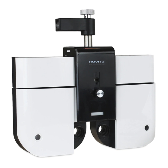
Also various accessories are summarized in the later part. 5.1. Digital Refractor Digital Refractor is most important part of the HDR-7000 system, and it is installed on a unit table like the Huvitz’s CRT or CST series models. ⑧... -
Page 23: Detail Explanation
------------------------------------------------------------------ HDR-7000 Operator’s Manual ⑨ ⑩ ⑪ ⑭ ⑫ ⑬ 5.1.1. Detail Explanation ① PD & Convergence Controller Part: the part which controls a pupil distance (PD) and the near point convergence. ② Disk Controller Part: the parts which control the disks and the disk lenses. -
Page 24: Junction Box (Jb)
HDR-7000 Operator’s Manual ------------------------------------------------------------------ ⑤ Forehead Rest Adjustment Knob: Used to move the Forehead Rest forward and backward in order to adjust the vertex distance (VD). ⑥ Near Point Rod Fixation Point: the place which affix the near point rod. -
Page 25: Detail Explanation
------------------------------------------------------------------ HDR-7000 Operator’s Manual ① ⑧ ⑦ ⑥ ⑤ ④ ③ ② 5.2.1. Detail Explanation ① Connector for Digital Refractor Port to connect the Junction Box to the Digital Refractor. ② Connector for Operation Panel Port to connect the Junction Box to the Operation Panel. -
Page 26: Operation Panel (Op)
HDR-7000 Operator’s Manual ------------------------------------------------------------------ ⑤ Connector for Global System network CAN-based instrument Port to connect the Local system to Global system network. Port to connect a terminator for termination. ⑥ Switch for Input Power Voltage ⑦ Switch for Power On/Off ⑧... -
Page 27: Detail Explanation: Front Side
------------------------------------------------------------------ HDR-7000 Operator’s Manual ⑥ ④ ⑤ 5.3.1. Detail Explanation: Front side ① LCD display & Touch Panel: This screen is for information about the optometry data and procedures. Touch screen provides that it will be able to select the buttons at the screen. -
Page 28: Detail Explanation: Rear Side
HDR-7000 Operator’s Manual ------------------------------------------------------------------ ① ② 5.3.2. Detail Explanation: Rear side ① Connector for the Junction Box: Port to connect the Operation Panel to the Junction Box. ② Connector for S/W upgrade: This port is used for downloading and upgrading the Operation Panel firmware. -
Page 29: Various Accessories
------------------------------------------------------------------ HDR-7000 Operator’s Manual 5.4. Various Accessories ※This section introduces the various accessories included for HDR-7000 system. 5.4.1. Accessories for Digital Refractor ① Forehead rest (1EA) ② Face shield (4EA) : 2EA attached, 2EA as spare ③ Near Point Card (1EA) ④... -
Page 30: Accessories For Operation Panel And Junction Box
HDR-7000 Operator’s Manual ------------------------------------------------------------------ 5.4.2. Accessories for Operation Panel and Junction Box Accessories for Operation Panel ① Printer Paper (3EA) : 1EA loaded in the printer, 2EA as spare ② Interface cable (1EA) : OP ↔ JB, 15-pin D-SUB Accessories for Junction Box ③... -
Page 31: Optional Accessories
------------------------------------------------------------------ HDR-7000 Operator’s Manual 5.4.3. Optional accessories ① Convert Box for Auto Ref/Keratometer ② Convert Box for Auto Lensmeter ③ Convert Box for PC ④ Terminator ⑤ Interface Cables for a Converter Box ↔ Converter Box: 9-pin D-SUB, 2m LM/RK/PC ↔... -
Page 32: System Installation
HDR-7000 Operator’s Manual ------------------------------------------------------------------ 5.5. System Installation Step 1 Check the instruments and its accessories listed in 5.4 and prepare them for installation. Step 2 Connect the Digital Refractor to the Junction Box (JB) with 24-pin DVI interface cable. Be sure not to connect or disconnect instruments to the junction Box while the power is on. -
Page 33: Basic Operations
------------------------------------------------------------------ HDR-7000 Operator’s Manual Basic Operations HDR-7000 system is constructed to manipulate essential functions using the dial, the buttons and the touch panel buttons on the operation panel. The dial, the buttons and the touch panel buttons have almost same functions. As user like to do, can manipulate it with ease. - Page 34 - (TIP) This button is useful if you are confused to find the exit method in certain dialog or screen. On behalf of pressing some buttons aimlessly to exit with luck, HDR-7000 system provides the [ESC] button consistently. In other words, whenever the [ESC] button is pressed, it goes to the main display without exception.
- Page 35 ------------------------------------------------------------------ HDR-7000 Operator’s Manual Unit Test button (TEST) - You can choose one from the 29 system-providing unit tests or from the 35 user-defined tests. Pressing the [CUSTOM] button in the Chart area of LCD Screen, it selects the user-defined test list directly.
- Page 36 - (TIP) You may change the behavior of [CLEAR] button as either ‘SOFT’ reset or ‘HARD’ reset in the page 7 of the system configuration menu. ‘HARD’ reset initializes the HDR-7000 physically from the beginning, not ОсОО «МЕДОФФ» www.medoff.net...
- Page 37 ------------------------------------------------------------------ HDR-7000 Operator’s Manual just removes the lenses and clears the data on the display. Print, Load and Mode Selection buttons - Prints the measured results. - Prints the results from other instruments if appropriate system option is set. - By setting the system option, Auto Clear, as ‘YES’, the whole test results are cleared automatically after printing out as just the way the [CLEAR] button works.
- Page 38 - Receives data from the RK/LM by pressing the [LOAD] button. - The transferred data to HDR-7000 system will be queued in regular sequence and the received data list up to now can be verified by selecting LM and RK in “Transferred Data”...
- Page 39 And then [LM] or [RK] lists will come out straightly - The more easy method to load from RK or LM is available. As you already have seen, HDR-7000 system supports stand alone mode. In stand lone mode, if either [RK] or [LM] button is pressed without entering “Transferred Area”(i.e.
- Page 40 Likewise, the [SET] buttons in the mask area can be pressed for setting up - HDR-7000 system provide [SET] button for the user confirmation. Almost every dialog box or menu selection supports [SET] button.
- Page 41 [ALT] button with user-defined buttons in the chart area combination makes the execution of the user-defined unit test possible. Like this, HDR-7000 system has arranged the function buttons very intuitively. Thus, it will be worth to try to make the [SHIFT] button with any other button combination by way of trial if necessary, case-by-case.
- Page 42 HDR-7000 Operator’s Manual ------------------------------------------------------------------ 16) Dial - Changes the field value(s), such as S, C, A, by the increment value selected - In the MENU mode, using menu item selection, changing option, and so on. - If [SHIFT] + Dial button pressed, can be configure Dial Click Configuration dialog box.
- Page 43 ------------------------------------------------------------------ HDR-7000 Operator’s Manual ОсОО «МЕДОФФ» www.medoff.net...
-
Page 44: Operation Of The Touch Screen Buttons
Now, it is time to discuss the features and functions of each touch buttons on the screen. As HDR-7000 system is made to maximize user’s convenience, you have only to be fully aware of these basic descriptions to proceed into basic optometry. - Page 45 ------------------------------------------------------------------ HDR-7000 Operator’s Manual - A: Cylinder Axis (R / L / OU) - ADD: Additional Power (R / L / OU) - VA: Visual Acuity (R / L / OU) - BIBO: Horizontal Prism (R / L / OU)
- Page 46 HDR-7000 Operator’s Manual ------------------------------------------------------------------ - To unlink VA charts (i.e. only chart is displayed, and other functions related with VA chart are disabled), press VA chart with the [SHIFT] button. - Sets red/green filter on a presented visual acuity chart. Pressing the button again removes the red/green filter set previously.
- Page 47 ------------------------------------------------------------------ HDR-7000 Operator’s Manual function is useful when explaining to customer with pointer at the screen. Buttons for Aux. Lenses - If “Aux. Lenses” is selected by lens touch button of the touch screen, without changing the current state, auxiliary lenses can be placed in the right/left eyes.
- Page 48 6ΔBU, Horizontal Maddox and Green Filter in the left eye only. The others can match for both eyes. [Table 1 shows auxiliary lenses usable with HDR-7000 system] NOTE 10ΔBl prism lens can be complemented with the prism value between 0 and 5. You may change this value in the "System Config"...
- Page 49 ------------------------------------------------------------------ HDR-7000 Operator’s Manual PD Input button (PD) - Press the [R]/[L] button of touch screen in the PD area to enter PD control mode for Right/Left eye and turn on the LED for VD check simultaneously. - To control R/L PD, press the data value of [R], [L] area and change by the dial.
-
Page 50: Menu Selection
HDR-7000 Operator’s Manual ------------------------------------------------------------------ Menu Selection HDR-7000 system supports various functions through menu selection. To select menu, just press the [MENU] button and press the Menu item of the touch screen. Otherwise, use the arrow buttons or the dial to move and the [SET] button to select. Menu item are as follows. -
Page 51: Test Result
------------------------------------------------------------------ HDR-7000 Operator’s Manual 7.1. Test Result If “Test Result” of the touch screen is selected (or pushing the [SET] button after selecting the desired item) use the arrow button or dial, the results can be verified by four ways in each near and far mode. Toggling near or far mode can be processed using the function button, [FAR] or [NEAR]. - Page 52 HDR-7000 Operator’s Manual ------------------------------------------------------------------ Also you can change the prism display on the table: To see the prism values in rectangular coordination (X/Y), press [X/Y] with [SHIFT]. To see the prism values in polar coordination (r/θ), press [r/ θ] with [SHIFT].
- Page 53 ------------------------------------------------------------------ HDR-7000 Operator’s Manual LIST2 : ADD, VA, BI/BO, BD/BU, NPC, NPA, Fusion (Worth 4 Dots), Stereo, Minute Stereo, and Aniseikonia. LIST3 : BLUR, BREAK, RECOVERY, NPC, NPA, Fusion (Worth 4 Dots), Stereo, Minute Stereo, and Aniseikonia. ОсОО «МЕДОФФ» www.medoff.net...
- Page 54 HDR-7000 Operator’s Manual ------------------------------------------------------------------ PRISM : Results of Schober, Von Graefe, Aniseikonia, Polarized Cross with the Fixation Point Test, Maddox Test, NRC and PRC Tests ОсОО «МЕДОФФ» www.medoff.net...
- Page 55 ------------------------------------------------------------------ HDR-7000 Operator’s Manual For your information, these are no separate menu but if the [PRINT] button is pressed during table view, the measured results will be printed on the paper via the built-in thermal printer. It goes through “Test Result” display in place of the direct printing on paper if “Preview List”...
- Page 56 HDR-7000 Operator’s Manual ------------------------------------------------------------------ Trial Lens Data: illustrates required information in brief to set up the trial lens. It also visually displays the S-C-A, BI/BO, BD/BU, PD values and the dominant eye. Ref. & Kerato Data: illustrates the Ref. & Kerato Data to the screen. It also visually displays the S-C-A-S.E power-R1/R2, PD values and the dominant eye.
- Page 57 ------------------------------------------------------------------ HDR-7000 Operator’s Manual ОсОО «МЕДОФФ» www.medoff.net...
-
Page 58: System Config
HDR-7000 Operator’s Manual ------------------------------------------------------------------ 7.2. System Config See chapter 8.2 “Description of options” for more information. ОсОО «МЕДОФФ» www.medoff.net... -
Page 59: Edit Program
------------------------------------------------------------------ HDR-7000 Operator’s Manual 7.3. Edit program See chapter 9.1 “Editing User-Designed Program” for more information. ОсОО «МЕДОФФ» www.medoff.net... -
Page 60: Edit Test
HDR-7000 Operator’s Manual ------------------------------------------------------------------ 7.4. Edit Test See chapter 9.2 “Editing User-Designed Unit Test” for more information. ОсОО «МЕДОФФ» www.medoff.net... -
Page 61: Edit Message
------------------------------------------------------------------ HDR-7000 Operator’s Manual 7.5. Edit Message See chapter 10 “Edit Message” for more information. ОсОО «МЕДОФФ» www.medoff.net... -
Page 62: Gallery
7.6. Gallery HDR-7000 system supports various kinds of near charts and images in the Operation Panel. There are unique vision test functions and it will be able to the test of near vision with various kind of near charts. In addition, it is possible to explain the customer about various of the ametropia or the disease. -
Page 63: Configuring The System
------------------------------------------------------------------ HDR-7000 Operator’s Manual Configuring the System HDR-7000 system provides various kinds of system configuration menu. Thus it is able to optimize optometry environment. You may start configuration by pressing the [MENU] button. Then select “System Config” of the touch screen. It is composed of 6pages and the major categories are as follows: “LENS &... -
Page 64: Button Operations
HDR-7000 Operator’s Manual ------------------------------------------------------------------ 8.1. Button operations Button operations for system configuration are introduced briefly. Moving: [BACK] and [NEXT] buttons of the touch screen are for moving page by page. Up and Down arrow buttons in the mask area are for moving field by field. - Page 65 ------------------------------------------------------------------ HDR-7000 Operator’s Manual Then, At one time will be disappears expanded combo-box and will be changed item value. ОсОО «МЕДОФФ» www.medoff.net...
-
Page 66: Description Of Options
HDR-7000 Operator’s Manual ------------------------------------------------------------------ 8.2. Description of Options Let’s find out which options are provided by each page. 8.2.1. Page 1 - LENS & DATA MANIPULATION (1) ① SPH step: sets the basic step for a SPH value. Choose one among 0.12D, 025D and 0.50D. -
Page 67: Lens & Data Manipulation (2)
------------------------------------------------------------------ HDR-7000 Operator’s Manual Try turning the dial while pressing the [SHIFT] button to make use of this option. ⑧ Δ Step [SHIFT]: sets the basic step for a prism value when the [SHIFT] button is pressed with, Choose one among 0.5Δ, 1.0Δ and 2.0Δ. Default value is 1.0 Δ. - Page 68 HDR-7000 Operator’s Manual ------------------------------------------------------------------ ① S.C: Auto Occlusion: assigns YES or NO whether auto occlusion for patient will be executed when the SPH and CYL lenses are changed by high diopter. Default value is YES. ② CC Type: sets the default cross cylinder lens type for the cross cylinder tests.
-
Page 69: Test & Data Manipulation (1)
------------------------------------------------------------------ HDR-7000 Operator’s Manual 8.2.3. Page 3 – TEST & DATA MANIPULATION (1) ① Δ Display: assigns the notational method for prism display. X/Y(Cartesian coordination) or r/θ(polar coordination) can be chosen. Default value is X/Y. ② Blur/Break/Recovery: specifies whether to display the function keys for executing NRC and PRC test on the horizontal prism adjustment mode that is entered by pressing the [BIBO] button. - Page 70 HDR-7000 Operator’s Manual ------------------------------------------------------------------ from the measurement(s) data, it can estimate expected VA of patient. So, it can present a VA chart and mask the expected line of the chart automatically. Unaided VA is estimated by the RK data and aided VA by the difference between the RK and LM data.
-
Page 71: Test & Data Manipulation (2)
------------------------------------------------------------------ HDR-7000 Operator’s Manual 8.2.4. Page 4 – TEST & DATA MANIPULATION (2) ① Default Program: assigns the system default program that is executed when the [START] button is pressed. Headed by STANDARD, up to 10 user-defined programs are available for the selection. Default value is STANDARD. - Page 72 HDR-7000 Operator’s Manual ------------------------------------------------------------------ result of Stereo & Minute Stereo Tests when the tests are executed. YES or NO can be chosen. Default value is YES. ④ Input Coincidence: specifies whether to display the function keys for inputting the result of Aniseikonia Test when the test is executed. YES or NO can be chosen.
-
Page 73: Test Environment
------------------------------------------------------------------ HDR-7000 Operator’s Manual 8.2.5. Page 5 - TEST ENVIRONMENT ① Beep Sound: specifies whether the beep sound will be turned on or off. ON or OFF can be chosen. Default value is ON ② Screen Off: specifies the activation time of the screen saver. Choose one from 0 minute (inactive) up to 1 hour at intervals of 5 minutes. -
Page 74: Print Option
HDR-7000 Operator’s Manual ------------------------------------------------------------------ ④ Date Display: specifies date format shown on the left-top area display. Choose one among ‘DD/MM hh:mi (12H)’, ‘DD/MM hh:mi (24H)’, ‘DD/MM’, ‘MM/DD hh:mi (12H)’, ‘MM/DD hh:mi (24H)’, ‘MM/DD’ and ‘NONE’. Default value is ‘DD/MM hh:mi (12H)’. DD stands for date, MM for month, hh for hour and mi for minute. - Page 75 ------------------------------------------------------------------ HDR-7000 Operator’s Manual subjective test. Choose One among ALL (all the data), W/O UNAIDED VA (without result unaided visual acuity), W/O BIN VF (without results of the visual function test ), SUBJ & FIN ONLY (showing only the SUBJ and FIN information) and OFF (without any subjective test).
- Page 76 HDR-7000 Operator’s Manual ------------------------------------------------------------------ ОсОО «МЕДОФФ» www.medoff.net...
-
Page 77: Editing User-Designable Program & Test
------------------------------------------------------------------ HDR-7000 Operator’s Manual Editing User-Designable Program & Test If user-designable programs are made matching for the doctor to use them and the purpose of the program in advance, the training cost will be greatly reduced and the inspection will be processed more quickly. You will catch two hares at a time. Unit test can be reformed to operator‘s capabilities and thus provides amazing enlargement. - Page 78 HDR-7000 Operator’s Manual ------------------------------------------------------------------ In the editing display, the Program name and the step are appeared on the top area. The first number stands for the current step and the second number following “/” for the whole steps. For instance, if the user-designable program has 10 steps all together and the current step is the 4th, “4/10”...
- Page 79 ------------------------------------------------------------------ HDR-7000 Operator’s Manual The [BACK] button of the touch screen in the bottom line goes to the previous step and the [NEXT] button to the next step. The [ADD] button adds a new step behind the last one and the [INS] button insert a new step before the current one. Press the [OK] button to confirm after defining program functions through all steps.
- Page 80 HDR-7000 Operator’s Manual ------------------------------------------------------------------ : Thumbnail window page down : [ADD] button : [DEL] button : select to each step The option elements for designing a user-defined program in the left-top side of the window are as follows: Test: the chart of the system test to apply. If ‘Test’ item is changed, related Chart, Data Element, Cross Cylinder, Fogging and Auxiliary Lens items will be changed at a time if possible.
- Page 81 ------------------------------------------------------------------ HDR-7000 Operator’s Manual Eye: assigns BIN(OU), LEFT or RIGHT. Press the combo-box button of the touch screen or press the [R], [OU] or [L] button to select this. Cross Cylinder: assigns 0.25, 0.50 or DUAL Cross Cylinder. Press the combo- box button of the touch screen to select this or press [1], [2] buttons to select this field.
- Page 82 HDR-7000 Operator’s Manual ------------------------------------------------------------------ Press the Letter Chart in initial display. Then the Test item changes to [VA- Letter] and the Chart item to [Letter-6]. Choose the Test and turn the dial to change Test and Chart Items. The simplified method is that press the Chart button of the touch screen and turn the dial to assign [BIN(OU)].
- Page 83 ------------------------------------------------------------------ HDR-7000 Operator’s Manual Let’s enter the third step. Similarly, press the [ADD] button to add the new display for the user-defined program. Push the Dots Group Chart in this display and the Chart item to [Dots Group]. After selecting the chart, subsequently choose the Test Mode (Dist.) combo-box button of the touch screen and select...
- Page 84 HDR-7000 Operator’s Manual ------------------------------------------------------------------ The 4th step. Also press the [ADD] button to add a new display for the user- defined program. Push the Dots Group Chart in this display. Because we are planning to measure not AXIS but CYL, push the Dots Group Chart once more to change the Test item and the Chart item to [Dots Group].
- Page 85 ------------------------------------------------------------------ HDR-7000 Operator’s Manual This is the 5th step. Repeat the procedures in 1). ОсОО «МЕДОФФ» www.medoff.net...
- Page 86 HDR-7000 Operator’s Manual ------------------------------------------------------------------ Since we have finished all steps, press [OK] button of the touch screen to save and exit. Push [SHIFT] + [START] button to see the program list which we composed just before and choose “CUSTOM-A” to launch this program in practice.
- Page 87 ------------------------------------------------------------------ HDR-7000 Operator’s Manual The next hint is how to apply the mask shifting button is pressed after spreading VA chart, right/left and up/down movements can be done naturally for the mask setting. The last hint is the various shortcuts. For example, if user wants to assign the left eye to the Eye item, just press the [L] button instead of turning the dial.
-
Page 88: Editing User-Designable Unit Test
HDR-7000 Operator’s Manual ------------------------------------------------------------------ 9.2. Editing User-Designable Unit Test If the user-defined program can be understood as it is, the Unit Test edition is not so hard. After pressing the [MENU] button and select “Edit Test” item of the touch screen to enter the Unit Test program editing function. - Page 89 ------------------------------------------------------------------ HDR-7000 Operator’s Manual If “CUSTOM-A1” is selected, the display similar to the user-defined program editing described in chapter 9.1 will appear. However the [BACK], [NEXT], [ADD], [INS] buttons are nowhere. But, it cab be operate using the buttons of thumbnail area. The Chart can be directly chosen.
- Page 90 HDR-7000 Operator’s Manual ------------------------------------------------------------------ touch screen select [NEAR] or [FAR] Data Element: assigns SPH, CYL, AXS, ADD, VA, BIBO, BDBU or ADDVA. Press the combo-box button of the touch screen or press the [S], [C], [A], [ADD], [VA], [BIBO], [BDBU] or [N ADD VA] button.
- Page 91 ------------------------------------------------------------------ HDR-7000 Operator’s Manual At first hand, press the Landolt-ring Chart button. The chart with 0.9(25 in 20/20, 7.5 in 6/6) will be suitable matching for the patient’s visual acuity. And press the Red/Green filter for Red/Green filter masking. At this point apply fog by about [0.5D] degree after selecting Fogging in the left window.
- Page 92 HDR-7000 Operator’s Manual ------------------------------------------------------------------ button and press [CUSTOM] button of the touch screen and select it. Let’s take another example. Use a Number Chart when processing the Dual Cross Cylinder Test. After pressing the [MENU] buttons, select “ Edit Test ” item of the touch screen and select one of the Unit Test item so as to enter the Unit Edit Test.
- Page 93 You may be worried that the test combined with the basic buttons might be gone away if a unit test is made like this. However, HDR-7000 system prevents not to override the system-provided basic tests absolutely. Therefore there is no situation on earth that basic test of your system could not be processed by your accidental or intentional mistakes.
- Page 94 HDR-7000 Operator’s Manual ------------------------------------------------------------------ ОсОО «МЕДОФФ» www.medoff.net...
-
Page 95: Editing Messages
------------------------------------------------------------------ HDR-7000 Operator’s Manual 10. Editing Messages 10.1. Introduction HDR-7000 system has the virtual keyboard to rewrite the message. You can edit the following message. Program Name: to change user defined program name Test Name: to change user defined unit test name... -
Page 96: How To Use Virtual Keyboard
HDR-7000 Operator’s Manual ------------------------------------------------------------------ 10.2. How to Use Virtual Keyboard You can edit message by pressing the button on the virtual keyboard. The virtual keyboard is composed of ‘SAVE’, ‘EXIT’ button, Message area, and Keyboard buttons. You can rewrite the message by using the virtual keyboard buttons as shown at the Figure. - Page 97 ------------------------------------------------------------------ HDR-7000 Operator’s Manual When you press the key on the virtual keyboard, the characters display on the Message area. If the last character is reached in the end of Message area, the control panel warns you using beep sound.
- Page 98 HDR-7000 Operator’s Manual ------------------------------------------------------------------ ОсОО «МЕДОФФ» www.medoff.net...
- Page 99 ------------------------------------------------------------------ HDR-7000 Operator’s Manual In addition, you can also use Keypad buttons. You can erase the part of or whole message by using [ ] or [ ] button. When you press [ ] button, the letter before the cursor is deleted and when you press [ button, the letter on the cursor is erased.
-
Page 100: Editing Program Name
HDR-7000 Operator’s Manual ------------------------------------------------------------------ 10.3. Editing Program Name We recommend that you rename the user-defined program to prevent confusion. For example, if you name CUSTOM-A “Children PROGRAM”, you can easily understand the program. It is better to understand to use “My Own Standard” rather than “CUSTOM-B”. -
Page 101: Editing Test Name
------------------------------------------------------------------ HDR-7000 Operator’s Manual 10.4. Editing Test Name Press [MENU] and select “Edit Message” and “Test Name” in order to edit the user- defined test name. Select the test name of the touch screen you want to edit. When you select ‘CUSTOM A1’, the initial program name ‘CUSTOM A1’ displays on the Message area of the virtual keyboard. -
Page 102: Editing Guide Message
60 characters at every test guide message. But, you cannot edit the system provided test guide message. Because of the long length of the guide message, the HDR-7000 system provides the function to copy and paste the message. Press [SYSTEM] button of the touch screen... - Page 103 ------------------------------------------------------------------ HDR-7000 Operator’s Manual in “Guide Message” editing mode to open the list of the system test guide message. Choose the test guide message you need and press [COPY] button of the touch screen to copy the message. Return to the test guide list by pressing [CUSTOM] button of the touch screen.
-
Page 104: Editing Shop Name
HDR-7000 Operator’s Manual ------------------------------------------------------------------ 10.6. Editing Shop Name You can print the prescription data including your shop name or telephone number. Press [MENU] and select “Edit Message” and “Shop Name” to write the printer footer. You can write maximum 72 characters in three rows. Press ‘SAVE’ button of the virtual keyboard to save the message. -
Page 105: Examination Modes
RK and LM measurement, in each mode and switching among memorized data with one touch of button for comparing those patient data. There are six different modes available on HDR-7000. EMPTY mode: This mode is the system default dummy mode where unclassified measurement may be memorized. - Page 106 HDR-7000 Operator’s Manual ------------------------------------------------------------------ To enter this mode, press the [SUBJ] button. At the first selection of this mode, one of the measurements from LM, RK, or previous mode is copied to SUBJ mode according to the system configuration. For more information, see the chapter 8 “Configuring the System”.
-
Page 107: Why Examination Mode Is Important
LCD screen beforehand have already been overwritten. However, with your smart HDR-7000 system, just press the [RK] button and change into RK mode then you can check the RK data with ease and convenient manner. - Page 108 HDR-7000 Operator’s Manual ------------------------------------------------------------------ Now, you curiously want to glance over the data from LM. As you know, by simply applying 2), just press the [LM] button right now to change mode and then read the data from LM. That’s all enough.
- Page 109 ------------------------------------------------------------------ HDR-7000 Operator’s Manual [SUBJ] mode you can change modes (SUBJ, RK, LM) freely and consequently compare SUBJ, RK, and LM values without the loss of data. [FIN] mode helps you to calibrate the final results for prescription. And also...
-
Page 110: Data Duplication
HDR-7000 Operator’s Manual ------------------------------------------------------------------ Various inspecting modes play an important role not to lose patient’s optometry information and hold data for each mode. Therefore, it is clear that they are inevitable when you gather and analyze all the information. And, each of the modes can be selected by the tab button of the touch screen. -
Page 111: Warnings On Mode
------------------------------------------------------------------ HDR-7000 Operator’s Manual 2) Starting from the [LM] data After changing mode into [LM], load data from a lensmeter. And then press [SUBJ] button to make automatic copy of the [LM] data into [SUBJ] mode. Also, you can see that changing into [SUBJ] mode is needed for preserving the reference data instead of working in [LM] mode. -
Page 112: Measuring Near And Far Vision
HDR-7000 Operator’s Manual ------------------------------------------------------------------ finally corrected state (FIN). By changing the ‘SUBJ Startup’ option in the system option, you can modify from which mode data will be duplicated when the [SUBJ] button is pressed. Options are as in the following figure. - Page 113 HDR-7000 system is designed to measure both near and far vision. If the [FAR] or [NEAR] button of the touch screen or [ADD] button is pressed, changing mode and tilting by Digital Refractor for measuring near vision occur automatically.
- Page 114 You can make a choice under your condition. Age data can be inputted after the [AGE] button of the touch screen is pressed. HDR-7000 system also provides automatic increase and decrease of the tilting angle, which result in saving of measurement time.
-
Page 115: Other Temporal Examination Modes
------------------------------------------------------------------ HDR-7000 Operator’s Manual After entering the near vision mode (including [ADD] mode), you measure how much degree your patient can see the chart by lowering the rod with near distance chart. Additional spherical power can also be inserted necessary. -
Page 116: Aux Off Mode
Digital Refractor. This makes patients comfortable especially when the RK/LM data is input manually because there is no auto ref/keratometer or auto lensmeter connected to HDR-7000 system. You can input S/C/A/ADD/VA/Prism data in this mode. -
Page 117: Add Off Mode
------------------------------------------------------------------ HDR-7000 Operator’s Manual 11.5.3. ADD OFF Mode ADD OFF mode temporarily removes addition power from the lens unit, Digital Refractor. If you press [ADD] button twice, it enters the ADD OFF mode. Pressing the [ADD] button again restores the system to the previous mode. -
Page 118: Prism Off Mode
HDR-7000 Operator’s Manual ------------------------------------------------------------------ 11.5.4. PRISM OFF Mode PRISM OFF mode temporarily removes prism power from the lens unit, Digital Refractor. If you press [BIBO] or [BDBU] button twice, it enters the PRISM OFF mode. Pressing the [BIBO] or [BDBU] button again restores the system to the previous mode. -
Page 119: Standard Program & Functions
By the system –defined program, operators can enjoy the various inspections provided with HDR-7000 system. Accordingly, this chapter explains the basic recipes for how to use HDR-7000 system and program execution methods by exploring the system- defined program carefully from beginning to end. -
Page 120: Adjustment Of The Sph-Cyl-Axis Values For Right Eye
HDR-7000 Operator’s Manual ------------------------------------------------------------------ 12.1.1. Adjustment of the SPH-CYL-AXIS Values for Right Eye The first step for the system-defined program is to coordinate the SPH-CYL-AXIS values for the right eye. Initial field value is adjusted to SPH for both eyes. Push the [R] or [L] button to enter monocular test mode and then modify SPH according to the patient’s condition. -
Page 121: Jackson Cross Cylinder Test(Axis) For Right Eye
------------------------------------------------------------------ HDR-7000 Operator’s Manual 12.1.2. Jackson Cross Cylinder Test(AXIS) for Right Eye The second step is to calibrate the AXIS value for the right eye minutely on the base of the resultant SPH-CYL-AXIS values from step 1. Press the [1]/[2] buttons that toggles the lens flipping during Jackson Cross Cylinder Test, and ask which status appears clearer. -
Page 122: Jackson Cross Cylinder Test(Cyl) For Right Eye
HDR-7000 Operator’s Manual ------------------------------------------------------------------ 12.1.3. Jackson Cross Cylinder Test(CYL) for Right Eye The third step is to calibrate the CYL value for the right eye minutely on the base of the resultant SPH-CYL-AXIS values from step 1. Press the [1]/[2] buttons that toggles the lens flipping during Jackson Cross Cylinder Test, and ask which status appears clearer. -
Page 123: Red/Green Test For Right Eye
------------------------------------------------------------------ HDR-7000 Operator’s Manual 12.1.4. Red/Green Test for Right Eye The fourth step is to calibrate the SPH value minutely for the right eye on the base of the resultant the SPH-CYL-AXIS values from step 1. First, ask your patient on which background he/she can see the letters more clearly, the green background or the red one. -
Page 124: Checking The Visual Acuity For Right Eye
HDR-7000 Operator’s Manual ------------------------------------------------------------------ 12.1.5. Checking The Visual Acuity for Right Eye Now, we finished the monocular test for the right eye, verify the right spherical power one more time. Use mask for the foregoing inspection if necessary. ОсОО «МЕДОФФ» www.medoff.net... -
Page 125: Adjustment Of The Sph-Cyl-Axis Values For Left Eye
------------------------------------------------------------------ HDR-7000 Operator’s Manual 12.1.6. Adjustment of the SPH-CYL-AXIS Values for Left Eye The sixth step is to coordinate the SPH-CYL-AXIS values for the left eye. See 12.1.1, Adjustment of the SPH-CYL-AXIS Values for Right Eye. 12.1.7. Jackson Cross Cylinder Test(AXIS) for Left Eye The seventh Step is to calibrate minutely the AXIS value for left eye on the base of the resultant SPH-CYL-AXIS value from step 6. -
Page 126: Jackson Cross Cylinder Test(Cyl) For Left Eye
HDR-7000 Operator’s Manual ------------------------------------------------------------------ Test(AXIS) for Right Eye. 12.1.8. Jackson Cross Cylinder Test(CYL) for Left Eye The eighth Step is to calibrate the CYL value minutely for the left eye on the base of the resultant SPH-CYL-AXIS value from step 6. See 12.1.3, Jackson Cross Cylinder Test(CYL) for Right Eye. -
Page 127: Checking The Visual Acuity For Binocular Vision
------------------------------------------------------------------ HDR-7000 Operator’s Manual the power on the clearer seeing eye until the patient reports equal blurriness. But, in case it’s impossible to achieve equal blurriness, leave the dominant eye with a bit clearer vision. 12.1.12. Checking The Visual Acuity for Binocular Vision Now, we finished the binocular balance test, verify the right and left spherical power one more time. -
Page 128: Horizontal Coincidence Test At Far
HDR-7000 Operator’s Manual ------------------------------------------------------------------ 12.1.13. Horizontal Coincidence Test at Far It performs an inspection using the horizontal coincidence chart among the binocular tests. According to the guide, execute the phoria and the coincidence test (optional) and then record the test results. See 13.24, Horizontal Coincidence Test for further information. -
Page 129: Near Addition Test With Fused Cross Cylinder Lenses
------------------------------------------------------------------ HDR-7000 Operator’s Manual and then record the test results. See 13.25, Vertical Coincidence Test for further information. 12.1.15. Near Addition Test with Fused Cross Cylinder Lenses It checks the Cross Grid Accommodation in near mode. According to the guide increase or decrease the ADD value. -
Page 130: Near Visual Acuity Test
HDR-7000 Operator’s Manual ------------------------------------------------------------------ 12.1.16. Near Visual Acuity Test It performs the Near VA with ADD test. See 13.1, ‘Near Visual Acuity Test’. ОсОО «МЕДОФФ» www.medoff.net... -
Page 131: Near Horizontal/Vertical Von Graefe Test
------------------------------------------------------------------ HDR-7000 Operator’s Manual 12.1.17. Near Horizontal/Vertical Von Graefe Test It performs Near Distance Horizontal and Vertical Von Graefe Test. According to the guide, do the phoria test. See 13.22, ‘Horizontal Von Graefe Test’ and 13.23, ‘Vertical Von Graefe Test’. - Page 132 HDR-7000 Operator’s Manual ------------------------------------------------------------------ Now, we have completed the standard tests including monocular correction (right) monocular correction (left) Binocular Balance Test Binocular Visual Function Test near distance test. ОсОО «МЕДОФФ» www.medoff.net...
-
Page 133: System-Providing Unit Tests
------------------------------------------------------------------ HDR-7000 Operator’s Manual 13. System-Providing Unit Tests There are total 29 system-providing unit tests available in HDR-7000 system. If you press [TEST] button, you can see the following list. We describe here each test to be referred to for the real optometry process. - Page 134 HDR-7000 Operator’s Manual ------------------------------------------------------------------ Dominant Eye for Phoria: Determining Dominant Eye for Phoria Hor. Maddox Rod: Horizontal Maddox Rod Test Vert. Maddox Rod: Vertical Maddox Rod Test Binocular Balance: Polarized Binocular Balance Test Polarized Red/Green : Polarized Red/ Green Test...
- Page 135 ------------------------------------------------------------------ HDR-7000 Operator’s Manual ОсОО «МЕДОФФ» www.medoff.net...
-
Page 136: Near Visual Acuity Test
HDR-7000 Operator’s Manual ------------------------------------------------------------------ 13.1. Near Visual Acuity Test - Objective: To inspect the Near VA with ADD - Chart: Near Distance chart - Auxiliary Lens: None - Expectation: To inspect Near VA with ADD for the right or left eye or for both eyes. - Page 137 ------------------------------------------------------------------ HDR-7000 Operator’s Manual Press the [N ADD VA] button and then the [NPC] button of the touch screen. Alternately, press the [TEST] button and then select “ Near Point of Converg ” item of the touch screen to execute this test.
-
Page 138: Near Point Of Accommodation Test
HDR-7000 Operator’s Manual ------------------------------------------------------------------ 13.3. Near Point of Accommodation Test - Objective: To measure the Near Point of Accommodation during the subjective test. - Chart: Near Distance chart - Auxiliary Lens: None - Expectation: To obtain the Near point of Accommodation for the right or left eye or for both eyes. -
Page 139: Near Addition Test With Fused Cross Cylinder Lenses
------------------------------------------------------------------ HDR-7000 Operator’s Manual 13.4. Near Addition Test with Fused Cross Cylinder Lenses - Objective: To correct the ADD according to the accommodation using Cross Grid - Chart: Near Distance (Cross Grid) chart - Auxiliary Lens: None - Expectation: To make the horizontal and vertical rods have the same clarity and the same width similar to Far Cross Grid Test. - Page 140 HDR-7000 Operator’s Manual ------------------------------------------------------------------ Cross Grid chart at 40cm. Alternately, press the [TEST] button and then select “Near ADD” of the touch screen to execute this test. Press the [R], [L], [OU] button to select the field to measure. Change the ADD value till the horizontal and vertical rods have the same clarity and width.
-
Page 141: Negative Relative Accommodation Test
------------------------------------------------------------------ HDR-7000 Operator’s Manual 13.5. Negative Relative Accommodation Test - Objective: To measure the Negative Relative Accommodation Test during the subjective test. - Chart: Near Distance chart - Auxiliary Lens: None - Expectation: To obtain BLUR and RECOVERY value for the right or left eye or for both eyes. -
Page 142: Positive Relative Accommodation Test
HDR-7000 Operator’s Manual ------------------------------------------------------------------ 13.6. Positive Relative Accommodation Test - Objective: To measure Positive Relative Accommodation during the subjective test. - Chart: Near Distance chart - Auxiliary Lens: None - Expectation: To obtain BLUR and RECOVERY value for the right or left eye or for both eyes. - Page 143 ------------------------------------------------------------------ HDR-7000 Operator’s Manual Press the [N ADD #] button and then the [PRA] button of the touch screen. Alternately, press the [TEST] button and then select “Positive Relative Accomm.” Item of the touch screen to execute this test. Press the [R], [L], [OU] button to select the field to measure.
-
Page 144: Negative Relative Convergence Test
HDR-7000 Operator’s Manual ------------------------------------------------------------------ 13.7. Negative Relative Convergence Test - Objective: To measure the Negative Convergence during the subjective test. - Chart: Near Distance chart - Auxiliary Lens: None - Expectation: To obtain BLUR, BREAK and RECOVERY value for the right or left eye or for both eyes. -
Page 145: Positive Relative Convergence Test
------------------------------------------------------------------ HDR-7000 Operator’s Manual At this time, turn the dial clockwise to subtract the BI prism. Press the [OK] button of the touch screen when the charts come together. All done. 13.8. Positive Relative Convergence Test - Objective: To measure the Positive Relative Convergence test during the subjective test. - Page 146 HDR-7000 Operator’s Manual ------------------------------------------------------------------ Press the [F/N] button of the touch screen to select near or far mode. Press the [BIBO] button and then the [PRC] button of the touch screen. Alternately, press the [TEST] button and then select “Positive Relative Convrg.”...
-
Page 147: Cylinder Axis Test
------------------------------------------------------------------ HDR-7000 Operator’s Manual 13.9. Cylinder Axis Test - Objective: To obtain maximum corrected monocular CYL value during the subjective test using the Clock Dial chart by 30˚steps. - Chart: Clock Dial chart - Auxiliary Lens: None - Expectation: All the rods on the screen can be seen uniformly clear. - Page 148 HDR-7000 Operator’s Manual ------------------------------------------------------------------ [TEST] button and then select “ Cylinder Test-Axis ” Item of the touch screen to execute this test Press the [R] or [L] button to select the desired field Press the [S] button to enter the spherical power mode and then apply fog till the numbers outside the Clock Dial appears to be clear.
-
Page 149: Cylinder Power Test
------------------------------------------------------------------ HDR-7000 Operator’s Manual 13.10. Cylinder Power Test - Objective: To obtain the maximum corrected monocular CYL value during the subjective test the Clock Dial chart. - Chart: Clock Dial chart - Auxiliary: None - Expectation: All the rods on the screen can be seen uniformly clear. -
Page 150: Red/Green Test
HDR-7000 Operator’s Manual ------------------------------------------------------------------ 13.11. Red/Green Test - Objective: To verify the maximum corrected monocular SPH value during the subjective test using the Red/Green chart. - Chart: Red/Green chart - Auxiliary Lens: None - Expectation: The letters on the red and green ground can be seen uniformly clear. -
Page 151: Jackson Cross Cylinder Test
------------------------------------------------------------------ HDR-7000 Operator’s Manual WARNING You should not ask the patient like “ which letters do you see more clearly, on the red ground or on the green one? ” According to the patient’s corrected visual acuity, in case of 1.0 (20 in 20/20, 6 in 6/6), ask concretely like “ On which ground do you see the number 2, 9 more clearly, red or green? ”... - Page 152 HDR-7000 Operator’s Manual ------------------------------------------------------------------ - Objective: To obtain the maximum corrected monocular CYL and AXIS values during the subjective test using the Jackson Cross Cylinder. - Chart: Dots Group chart - Auxiliary Lens: Cross Cylinder Lens (025/050) - Expectation: The Dots Group Chart can be seen uniformly clear in spite of the up and down movement of the Cross Cylinder.
-
Page 153: Dual Cross Cylinder Test
------------------------------------------------------------------ HDR-7000 Operator’s Manual This test is ended if there is no difference in the result of the button [1] and [2]. 13.13. Dual Cross Cylinder Test - Objective: To obtain the maximum corrected monocular CYL and AXIS during the subjective test using Dual Cross Cylinder. - Page 154 HDR-7000 Operator’s Manual ------------------------------------------------------------------ Press the Dots Group Chart to enter the Cross Cylinder test mode. Alternately, press the [TEST] button and then select “Cross Cyl. Test-Axis” Item of the touch screen to execute this test. Select the desired field by pressing the [R] or [L] button.
-
Page 155: Cross Grid Test For Distance
------------------------------------------------------------------ HDR-7000 Operator’s Manual 13.14. Cross Grid Test for Distance - Objective: To obtain the maximum corrected monocular SPH using Far Cross Grid chart. (Accommodation) - Chart: Cross Grid for Distance chart (with CCP-3100, CDC-4000 only) - Auxiliary Lens: Fixed Cross Cylinder Lens - Expectation: The Horizontal and Vertical rods can be seen uniformly distributed and equally clear. - Page 156 HDR-7000 Operator’s Manual ------------------------------------------------------------------ Press Cross Grid for Distance chart to enter this mode. Alternately, press the [TEST] button and then select “Cross Grid for Dist” Item of the touch screen to execute this test. Select the desired field by pressing [R] or [L] button.
-
Page 157: Dominant Eye Test For Phoria
------------------------------------------------------------------ HDR-7000 Operator’s Manual WARNING You should correctly set astigmatism axis and cylindrical power before doing this test to prevent the influence of direct or indirect astigmatism. 13.15. Dominant Eye Test for Phoria - Objective: To find the dominant eye for phoria since the patient with phoria has dominant eye in a slightly different way compared to a normal case. - Page 158 HDR-7000 Operator’s Manual ------------------------------------------------------------------ Maddox Rod. - Chart: Maddox Rod chart - Auxiliary Lens: Horizontal Maddox (right), Rotary Prism (left) - Expectation: The vertical rod for the right eye is united with the Maddox Chart for the left eye. - Operation Sequence: Press the Maddox Chart to enter the Maddox Rod Test mode.
-
Page 159: Vertical Maddox Test
------------------------------------------------------------------ HDR-7000 Operator’s Manual 13.17. Vertical Maddox Test - Objective: To execute a vertical Phoria test during the subjective test using the Maddox Rod chart. - Chart: Maddox Rod chart - Auxiliary Lens: Rotary prism (right), Vertical Maddox (left) - Expectation: The horizontal rod for the left eye is united with the Maddox Chart for the right eye. - Page 160 HDR-7000 Operator’s Manual ------------------------------------------------------------------ To enter this mode, press the Maddox Chat twice, or press the [BDBU] button and then press The Maddox chart, or press [SHIFT] button and the Maddox chart at a time. The prism change window is presented in the left-top area and the Guide Window in the right-top area.
-
Page 161: Polarized Binocular Balance Test
------------------------------------------------------------------ HDR-7000 Operator’s Manual 13.18. Polarized Binocular Balance Test - Objective: To adjust binocular balance during the subjective test - Chart: Polarized Binocular Balance chart - Auxiliary Lens: 135˚Polarizing Filter (right), 45˚ Polarizing Filter (left) - Expectation: The upper row for the right eye and the lower row for the left eye appear to be similarly clear. - Page 162 HDR-7000 Operator’s Manual ------------------------------------------------------------------ WARNING If the patient has the dominant eye and the difference is equal to or less than 0.22D (maximum 0.5D), The polarized Binocular Balance Test may be omitted because the patient has of course the better sight with the dominant eye.
-
Page 163: Polarized Red/Green Test
------------------------------------------------------------------ HDR-7000 Operator’s Manual 13.19. Polarized Red/Green Test - Objective: To adjust the monocular and binocular balance at the same time during the subjective test. - Chart: Polarized Red/Green chart - Auxiliary Lens: 135˚ Polarizing Filter (right), 45˚ Polarizing Filter (left) - Expectation: The upper row for the right eye and the lower row for the left eye can be seen uniformly clear. - Page 164 HDR-7000 Operator’s Manual ------------------------------------------------------------------ After pressing the [L] button, If the left side (red) is seen more clearly, turn the dial clockwise (“-“ direction). If the right side (green) is seen more clearly, turn the dial counterclockwise (“+” direction). Adjust the binocular balance after the right and left maximum corrected monocular SPH values are balanced.
-
Page 165: Worth 4 Dots Test
------------------------------------------------------------------ HDR-7000 Operator’s Manual 13.20. Worth 4 Dots Test - Objective: To find suppression during the subjective test. It is possible to check the internal or external phoria. - Chart: Worth-4-Dots chart - Auxiliary Lens: Red Filter (right), Green Filter (left) - Expectation: To check how many dots can be seen. - Page 166 HDR-7000 Operator’s Manual ------------------------------------------------------------------ Vision of patient Analysis Details 4 spots : red, : green, : pink or red/green alternately Fusion red: When the right eye is dominant., green: When the left eye is dominant 3 spots Right eye is...
-
Page 167: Schober Test
------------------------------------------------------------------ HDR-7000 Operator’s Manual 13.21. Schober Test - Objective: To execute a phoria test during the subjective test using the Schober chart - Chart: Schober chart (with CCP-3100, CDC-4000 only) - Auxiliary Lens: Red Filter (right), Green Filter (left), Binocular Rotary Prism - Expectation: To make the cross mark (for the right eye) placed the center of the circle. - Page 168 HDR-7000 Operator’s Manual ------------------------------------------------------------------ If “Under”: the right eye with hyperphoria. Press the Schober chart or the [BDBU] button once more and then the dial counterclockwise till the cross mark falls to the center of the circle. 10. After finishing this test, press the [OK] button of the touch screen to save (each...
-
Page 169: Horizontal Von Graefe Test
------------------------------------------------------------------ HDR-7000 Operator’s Manual Vision of patient Heterophoria Correction Method The cross mark is to the right Turn the dial clockwise to add of the circle Esophoria the BO prism till the cross mark comes to the center of the circle. - Page 170 HDR-7000 Operator’s Manual ------------------------------------------------------------------ Press the Von Graefe Chart to enter the horizontal phoria mode. Alternately, press the [TEST] button and then select “ Hor. Von Graefe ” Item of the touch screen to execute this test. Ask the patient as follows; “Are the two vertical rods vertically aligned?”...
- Page 171 ------------------------------------------------------------------ HDR-7000 Operator’s Manual WARNING If you make use of an old-fashioned chart projector or a mirror chart not supporting the Von Graefe Chart, you can imitate the horizontal Von Graefe chart as follows; 1. Spread a general chart readable to patient such as number, Landolt Ring, Snellen E.
-
Page 172: Vertical Von Graefe Test
HDR-7000 Operator’s Manual ------------------------------------------------------------------ 13.23. Vertical Von Graefe Test - Objective: To execute a vertical phoria test during the subjective test using Von Graefe chart. - Chart: Vertical Von Graefe chart - Auxiliary Lens: Rotary prism (right), 10ΔBI prism (left) - Expectation: To make the right and left horizontal rod becomes horizontally aligned in the center. -
Page 173: Horizontal Coincidence Test
------------------------------------------------------------------ HDR-7000 Operator’s Manual 13.24. Horizontal Coincidence Test - Objective: To execute the Coincidence and a horizontal phoria test during the subjective test using Coincidence chart - Chart: Horizontal Coincidence chart - Auxiliary Lens: 135˚ Polarizing Filter (right), 45˚ Polarizing Filter (left) - Expectation: The upper frame for the right eye and the lower frame for the left eye form an ideal square. - Page 174 HDR-7000 Operator’s Manual ------------------------------------------------------------------ To enter this mode, press the Coincidence chart. Alternately, press the [TEST] button and then select “Hor. Conincidens” Item of the touch screen to execute this test. Ask the patient as follows; “Can you see a square with a point at the center?”...
-
Page 175: Vertical Coincidence Test
------------------------------------------------------------------ HDR-7000 Operator’s Manual 13.25. Vertical Coincidence Test - Objective: To execute a vertical phoria test during the subjective test using the Coincidence chart - Chart: Vertical Coincidence chart - Auxiliary Lens: 135˚ Polarizing Filter (right), 45˚ Polarizing Filter (left) - Page 176 HDR-7000 Operator’s Manual ------------------------------------------------------------------ To enter this mode, press the Coincidence chart twice or [SHIFT] and Coincidence chart at a time. Alternately, press the [TEST] button and then select “Vert. Conincidens” Item of the touch screen to execute this test.
-
Page 177: Polarized Cross Test
------------------------------------------------------------------ HDR-7000 Operator’s Manual 13.26. Polarized Cross Test - Objective: To execute a phoria test during the subjective test using the polarized Cross chart without the fixation Point chart - Chart: Cross without the Fixation Point chart - Auxiliary Lens: 135˚ Polarizing Filter (right), 45˚ Polarizing Filter (left) - Expectation: The upper-right cross mark for the right eye and the lower-left cross mark for the left eye are overlapped into one ideal cross. - Page 178 HDR-7000 Operator’s Manual ------------------------------------------------------------------ To enter this mode, press the Polarized Cross Chart twice or the [SHIFT] button and the Polarized Cross Chart at a time. Alternately, press the [TEST] button and then select “Pola Cross” Item of the touch screen to execute this test.
-
Page 179: Polarized Cross Test With Fixation Point
------------------------------------------------------------------ HDR-7000 Operator’s Manual 13.27. Polarized Cross Test with Fixation Point - Objective: To execute the phoria test during the subjective test using the Polarized Cross chart with the Fixation Point chart. - Chart: Polarized Cross with the Fixation Point chart - Auxiliary Lens: 135˚... - Page 180 HDR-7000 Operator’s Manual ------------------------------------------------------------------ To enter this mode, press the Polarized Cross Chart. Alternately, press the [TEST] button and then select “Pola Cross w/ Fix” Item of the touch screen to execute this test. Ask the patient as follows; “Can you see one ideal cross mark?”...
- Page 181 ------------------------------------------------------------------ HDR-7000 Operator’s Manual ОсОО «МЕДОФФ» www.medoff.net...
- Page 182 HDR-7000 Operator’s Manual ------------------------------------------------------------------ Vision of patient Heterophoria Details Turn the dial clockwise to add the BO prism Esophoria till the vertical bar comes to the center of the horizontal bar. Turn the dial counterclockwise to add the BI Exophoria prism till the vertical bar comes to the center of the horizontal bar.
-
Page 183: Stereo Test
------------------------------------------------------------------ HDR-7000 Operator’s Manual 13.28. Stereo Test - Objective: To execute the Stereo test during the subjective test. - Chart: Stereo chart - Auxiliary Lens: 135˚ Polarizing Filter (right), 45˚ Polarizing Filter (left) - Expectation: The upper rod for the right eye appears to be closer to the patient than the lower rod for the left eye. -
Page 184: Minute Stereo Test
HDR-7000 Operator’s Manual ------------------------------------------------------------------ 13.29. Minute Stereo Test - Objective: To execute the Minute Stereo Test during the subjective test. - Chart: Minute Stereo chart - Auxiliary Lens: 135˚ Polarizing Filter (right), 45˚ Polarizing Filter (left) - Expectation: Starting from the central fixation point, clockwise, the next rods pair appear to be more and more close and clear to the patient than the previous one. - Page 185 ------------------------------------------------------------------ HDR-7000 Operator’s Manual “Minute Stereo” Item of the touch screen to execute this test. Ask the patient as follows; “How do you see the rods from the upper rods in 12 o’clock direction to 3, 6 and 9 o’clock directions one after another with the fixation point at the center?”...
- Page 186 HDR-7000 Operator’s Manual ------------------------------------------------------------------ ОсОО «МЕДОФФ» www.medoff.net...
-
Page 187: Examination Results And Printout
After finishing all the inspection processes, you may print the results either on the screen or on the paper. Since HDR-7000 system provides various options to save printing paper, refer the related Chapter 8, Configuring the System with this chapter. -
Page 188: Print On The Paper
HDR-7000 Operator’s Manual ------------------------------------------------------------------ + [PRINT]. Then the summarized results will be shown either in table and graphical form on the LCD screen. We will discuss printing on paper in 14.2 and printing on screen in 14.3. 14.2. Print on the Paper If you configure options do as to carry out all the inspections and print all the results thoroughly, the printing results would be of great amount. - Page 189 ------------------------------------------------------------------ HDR-7000 Operator’s Manual Patient’s identifier Patient’s name and sex Inspection Date and TIME Patient’s age and the dominant eye PD (near/Far) Unaided Visual Acuity NEAR Data from Lensmeter (Aided) Visual Acuity Data from Refractometer ОсОО «МЕДОФФ» www.medoff.net...
- Page 190 HDR-7000 Operator’s Manual ------------------------------------------------------------------ Data from Subjective Test Additional Visual Acuity Visual Acuity NEAR Visual Acuity Final Data Additional Visual Acuity Visual Acuity ОсОО «МЕДОФФ» www.medoff.net...
- Page 191 ------------------------------------------------------------------ HDR-7000 Operator’s Manual NEAR Visual Acuity Binocular Visual Function Test Schober Von Graefe Coincidence ОсОО «МЕДОФФ» www.medoff.net...
- Page 192 HDR-7000 Operator’s Manual ------------------------------------------------------------------ Polarized Cross without Fixation Point Polarized Cross with Fixation Point Maddox Rod NEAR Schober Von Graefe Coincidence Polarized Cross without Fixation Point Polarized Cross with Fixation Point Maddox Rod ОсОО «МЕДОФФ» www.medoff.net...
- Page 193 ------------------------------------------------------------------ HDR-7000 Operator’s Manual Fusion Stereo Minute Stereo Aniseikonia NEAR Fusion Data from Keratometry Test Time ОсОО «МЕДОФФ» www.medoff.net...
- Page 194 HDR-7000 Operator’s Manual ------------------------------------------------------------------ As we stated before, normally you don’t have to print so many results like the previous sample. Thus, remove the unessential options in system configuration. Enter page 6, PRINT OPTION in system configuration menu to turn on and off the following options as your needs.
-
Page 195: Print On The Screen
14.3. Print on the Screen If [SHIFT] + [PRINT] button is pressed, the summarized information will be shown on the LCD screen. HDR-7000 system shows the results divided into NEAR and FAR in a condensed from and helps display conversion by using function buttons. -
Page 196: Maintenance
HDR-7000 Operator’s Manual ------------------------------------------------------------------ 15. Maintenance 15.1. Replacing Printing Paper Replace the roll of printing paper as soon as possible after the red line appears on the paper according to the procedure below: Tilt the LCD monitor 90° degree to open the printer cover. -
Page 197: Replacing Fuse
------------------------------------------------------------------ HDR-7000 Operator’s Manual INFORMATION Use a thermal printing paper of width 57mm and diameter of roll 25mm. 15.2. Replacing Fuse Power Connector Fuse Holder [Junction Box] Turn off and disconnect the power cord. Pull out the fuse holder. Replace old fuse(s) with new one(s). -
Page 198: Cleaning
15.4. Storage If the instrument, HDR-7000 Digital Refractor, is not to be used for a long time, it is recommended to disconnect the power supply and protect the Refractor Body with dust cover. -
Page 199: Disposal
------------------------------------------------------------------ HDR-7000 Operator’s Manual 15.5. Disposal NOTE To dispose the instrument, accessories, and components, follow local governing ordinances and recycling plans regarding disposal or recycling of instrument or device components. Especially a lithium battery may pollute the environment if the instrument or a lithium battery is abandoned. -
Page 200: Troubleshooting
HDR-7000 Operator’s Manual ------------------------------------------------------------------ 16. Troubleshooting 16.1. Digital Refractor doesn’t work at all Check if power cord is connected correctly. Check if the 24-pin and 15-pin cables for the Refractor Body and the Operation Panel are connected correctly. Check if any of the fuses in the Junction Box is blown off. -
Page 201: Chart Presenting Device Doesn't Respond To Operation Panel
BPS: 9600 RS232C: LMTORK Check if the Converter Box connecting the auto ref/keratometer or the auto lensmeter to HDR-7000 Junction Box is turned on. Since old models don’t supply power to Converter Box through serial interface cable, appropriate ОсОО «МЕДОФФ» www.medoff.net... -
Page 202: All The Polarization Tests Are Not Working
HDR-7000 Operator’s Manual ------------------------------------------------------------------ power adaptor should be connected to Converter Box(MRK-3100P, HRK- 7000/7000A, CLM-3100P/4000, HLM-7000 or newer models supply power to Converter Box.) 16.7. All the polarization tests are not working Check if the vinyl sticker on the chart reflection plate is removed. -
Page 203: Specifications
------------------------------------------------------------------ HDR-7000 Operator’s Manual 17. Specifications Measurement Range -29.00 ~ +26.75D (Regular) Spherical Lens -19.00 ~ +16.75D(During XC or prism tests) (0.12/0.25/0.5/1/2/3/4D increments) 0.00 ~ ±8.75D (0.25/0.5/1/2/3D increments) Cylinder Lens Cylinder Axis 0˚~ 180˚ (1/ 5/ 15˚ increments) 48 ~ 80mm (0.5/1mm increments) - Page 204 HDR-7000 Operator’s Manual ------------------------------------------------------------------ . Digital Refractor : 9V 2A, 17V 5A Power Supply . Operation Panel : 9V 1A, 12V 1.2A, 5V 3A . Junction Box : 100~120/200~240 V~ 2A 50/60Hz Auxiliary Lenses Occluding Aperture ∅2mm Pinhole Lens Maddox Rod...
-
Page 205: Components And Options
------------------------------------------------------------------ HDR-7000 Operator’s Manual 18. Components And Options 18.1. Standard Package Components Refractor Body(HDR-7000 Digital Refractor) 1 EA Operation Panel(HDR-7000 Digital Refractor(OP)) 1 EA Junction Box(HDR-7000 Digital Refractor(JB)) 1 EA Forehead Rest 1 EA Face Shield 4 EA Near Point Card... -
Page 206: Optional Interface Package
HDR-7000 Operator’s Manual ------------------------------------------------------------------ 18.2. Optional interface Package Auto Ref/Keratormeter Package RK-type Converter Box 1 EA Interface Cable(4-pin CAN) 1 EA Interface Cable(9-pin D-SUB) 1 EA Power Adaptor 1 EA Terminator 1 EA Auto Lensmeter Package LM-type Converter Box 1 EA... -
Page 207: Service Information
Descriptions of Problem: in detail Date of Purchase: Dealer’s Name: Dealer Address: Dealer Phone No.: Model No.: Serial No.: Huvitz recommends customers to fill up the above form after purchase and retain this manual as a permanent record of purchase.) ОсОО «МЕДОФФ» www.medoff.net... - Page 208 HDR-7000 Operator’s Manual ------------------------------------------------------------------ Contact us at: HUVITZ Co., Ltd. Tel: +82-31-442-8868 Huvitz B/D, 689-3 Geumjeong-dong Fax: +82-31-442-8619 Gunpo-si Gyeonggi-do, 435-862, http://www.huvitz.com Republic of Korea e-mail: info@huvitz.com ОсОО «МЕДОФФ» www.medoff.net...
Need help?
Do you have a question about the HDR-7000 and is the answer not in the manual?
Questions and answers