Table of Contents
Advertisement
Advertisement
Table of Contents

Related Manuals for Huvitz HDR-9000


Summary of Contents for Huvitz HDR-9000
- Page 1 Service Manual Digital Refractor HDR-9000 HUVITZ Co. Ltd.
- Page 2 - 1 -...
-
Page 3: Table Of Contents
Contents Contents ..............................2 1. Introduction ............................4 2. Before Getting Started ........................5 2.1 Checking Software Versions ...................... 5 2.2 Setting-Up System Parameters ....................6 2.3 Using Engineer Mode ........................ 7 3. Confirmation Check Procedure ......................9 3.1 Purpose of Confirmation Check ....................9 3.2 Confirmation Check ........................ - Page 4 Appendix ............................. 42 Checking Software Versions ....................42 System Setting ........................44 Communication ........................47 Calibrating Touch Pad ......................51 Using Engineer Mode ......................53 Upgrading Software ......................65 - 3 -...
-
Page 5: Introduction
1. Introduction This manual provides information about maintenance on HUVITZ refractor Model HDR-9000. For correct maintenance, it is necessary to understand this manual thoroughly before beginning any treatment on the instrument. In case the instrument cannot be repaired by the procedures described in this manual, contact and inform our technical service department of the detailed information about your problem with product number and software version. -
Page 6: Before Getting Started
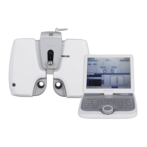
Technical Support Department at Huvitz. HDR-9000 Digital Refractor is consists of three parts, Refractor Body, Operation Panel and Junction Box. The Refractor Body is functionally divided into three parts, upper head, right and left battery. -
Page 7: Setting-Up System Parameters
2.2 Setting-Up System Parameters It is very common to interface HDR-9000 Digital Refractor with several different optometric instruments. But it varies from customer to customer that what kinds of and how many instruments are interfaced with. So it’s required for the engineer who installs and sets up refraction system at customer’s place to set up initial system parameters according to customer ’s needs and environment. -
Page 8: Using Engineer Mode
Refer to appendix for more detailed information about system setting. There are more parameters that customer can set up according to his or her flavor. Just refer to the Operator’s Manual and find the chapter that explains ‘System Configuration’ menu. 2.3 Using Engineer Mode When you’re referring this manual you may often encounter parts that ask you to execute ‘Engineer Mode’... - Page 9 [Engineer Mode] Refer to appendix for more detailed information about this mode. - 8 -...
-
Page 10: Confirmation Check Procedure
3. Confirmation Check Procedure 3.1 Purpose of Confirmation Check The purpose of inspecting the Huvitz product before taking it out for installation at customer’s place is to find out possible defects or changes on original alignment made on them during the shipping and to confirm the settings for normal operation. -
Page 11: Post Aging Test Procedures For The Refractor Body
Press FAR and NEAR button on the display several times. Check if the Refractor Body is converging correctly. Stop this step when the HDR-9000 Refractor Body is in FAR mode. ③ Check the initialization sequences again. Turn off the power. -
Page 12: Checking Procedures For The Operation Panel
Skip SPH and CYL lenses by pressing ‘+’ button 4 times. Check the auxiliary lenses one by one by comparing the lenses in the test windows of Refractor Body with the information on the LCD of the Operation Panel. ... - Page 13 3.2.4 Checking Procedures for Data Communication ① Checking with Ref/Keratometer. - Check the Option menu of MRK or HRK for the communication. Set the BPS option to 9600. - Measure a model eye or a patient. - Press PRINT button for transferring the measured data. - Press RK button with SHIFT pressed on the Operation Panel after the MRK or HRK finishes printing.
- Page 14 ⑤ Checking with HDC-7000~ 9000 - Check the System Settings menu of the Operation Panel for HDC-7000. Set the Chart Connection option to SERIAL or IR. Set the Chart Device option to HDC-7000. - Store the change by pressing the button OK or “HOME” button on the display. - Press some chart buttons and check the response of HDC-7000.
-
Page 15: Disassembling Procedure And Parts Description
4. Disassembling procedure and Parts Description 4.1 Removing the Covers - Unscrew the M3 set screw in the Forehead Adjustment Knob first. - Remove the Forehead Adjustment Knob. M3 set Screw Forehead Adjustment Knob - Remove the HEADREST. - Remove the EYE-COVE R. - Remove the BOLT-CAP with pincette. - Page 16 - Unscrew 3- M2.6 screws and remove the CABLE-COVER. - Unscrew 8- M2.6 screws and remove the CASE-R / CASE-L. CABLE COVER CASE-R CASE-L - 15 -...
- Page 17 - Unscrew - M2.6 screws and remove BACK-CAP BACK-CAP - 16 -...
- Page 18 - Unscrew 3- M2.6 screws and remove TOP-FRONT-CASE TOP-FRONT-CASE - 17 -...
- Page 19 - Unscrew 6- M2.6 screws and remove INNER-CASE-L / INNER-CASE-R INNER-CASE-L INNER-CASE-R - 18 -...
-
Page 20: Replacing The Circuit Board
4.2 Replacing the Circuit Board - Make it sure to turn off the power before removing the covers or replacing the circuit board. - Disconnect all the connectors from the circuit board and unscrew 6 screws. PCB ASSY(RBH300) - 19 -... -
Page 21: Description Of Parts
4.3 Description of Parts 4.3.1 Disk Assembly – Patient’s Side Cylinder Axis Motor Ass’y Cylinder Axis PI Ass’y MOTOR BOARD MOTOR BOARD DISK ASSY SUB1 GEAR 120 ASSY CONNECTION GEAR SERIES Frame Sub Ass’y - 20 -... -
Page 22: Disk Assembly - Examiner's Side
4.3.2 Disk Assembly – Examiner’s Side Outer Prism PI Ass’y Inner Prism Motor Ass’y Outer Prism Motor Ass’y Disk_4 Motor Ass’y SUB1 GEAR 120 ASSY Disk_6 Motor Ass’y Disk_5 Motor Ass’y - 21 -... -
Page 23: Sub1 Gear 120 Ass'y
4.3.3 SUB1 GEAR 120 ASS’Y PART NAME M2*5 Screw main_shaft_fixer Teflon_dia24*dia15*T0.1 sub1_gear120 NTB1024 sub_gear_axis - 22 -... -
Page 24: Sub1 Gear 120 Dual Ass'y
4.3.4 SUB1 GEAR 120 DUAL ASS’Y PART NAME sub_gear_2_shaft sub1_gear120 Teflon_dia24*dia15*T0.1 main_shaft_fixer NTB1024 M2*5 Screw - 23 -... -
Page 25: Hall Sensor Ass'y
4.3.5 HALL Sensor Ass’y Holes for Disk Ass’y on right-hand Holes for Disk Ass’y on left-hand PART NAME Flat M3*6 Screw PCB ASSY magnet sensor guide - 24 -... -
Page 26: Replacement Procedure Of Sensors
Before replacing any sensor, PI or HALL sensor, contact the customer service department at Huvitz and get enough information and instructions. Turn off the power and remove the covers of both the upper head and right or left body. - Page 27 - Turn on the power and check if the initialization sequence is performed correctly. All the open apertures of the disks should be aligned concentric after the initialization sequence. Otherwise contact the customer service department at Huvitz for further measurement and instructions.
- Page 28 Incorrect Position Correct Position Open Aperture in a disk which Open Apertures is off-centric. of 5 disks All Open Apertures are concentric Incorrect Position Correct Position Open Aperture of Disk #5 Open Aperture of Disk #6 All Open Apertures are concentric - 27 -...
-
Page 29: Disassembling The Operation Panel
4.5 Disassembling the Operation Panel Removing procedure for the bottom case of the Operation Panel - 28 -... -
Page 30: Removing The Lcd Panel Cover Of The Operation Panel
4.6 Removing the LCD Panel Cover of the Operation Panel - 29 -... -
Page 31: Replacing Printing Paper
4.7 Replacing Printing Paper Replace the roll of printing paper as soon as possible after the red line appears on the paper according to the procedure below: Tilt the LCD monitor 90° degree to open the printer cover. Pull the opening lever on the printer cover. Pull the remaining paper out. -
Page 32: Disassembling The Junction Box
4.8 Disassembling the Junction Box - 31 -... -
Page 33: Cleaning The Lenses In The Refractor Body
4.9 Cleaning the Lenses in the Refractor Body HDR-9000 Digital Refractor is designed to allow service engineers cleaning the lenses inside for maintenance. To clean the lenses in the Refractor Body, just follow the sequence below. (1) Remove the cover glasses from both the patient’s and the examiner ’s side so that a service engineer have access to the internal lenses. - Page 34 (2) Check the connection and turn on the Digital Refractor. If it has no problem during its initialization sequence, proceeds to the next cleaning procedure. (3) Execute the Engineer Menu mode on the Operation Panel. Refer to appendix for detailed information about entering and operating functions of Engineer Menu mode. (4) Execute the Lens Check function in the Engineer Menu mode.
-
Page 35: Trouble Shooting
5. Trouble shooting 5.1 Wiring Diagram and Board Description 5.1.1 Operation Panel Wiring Diagram - 34 -... - Page 36 Board Description Item Code Description Remarks D6EPCB0006-AA PCB ASSY D6, OP MAINBOARD, ROBASE-100 D6, OP LCD TOUCH BOARD, D6EPCB0008-AA PCB ASSY ROTOUCH-100 D6, OP SWITCH BOARD, D6EPCB0007-AA PCB ASSY ROSWITCH-100 TPH(THERMAL 6400TPH0641-A SMP640UG PRINTER HEAD) CLAA104XA02CW(CPT), H3104A- 7202LGRCLH3-B LCD MONITOR HDN3D62 6440ERO205B-A ENCODER...
-
Page 37: Refractor Body
5.1.2 Refractor Body Wiring Diagram - 36 -... - Page 38 J8,AXIS J12,PI-AXIS J1,SPH0 J3,CYL0 J2,SPH1 J13,hall sensor J10,inner prism J11,PI-outer prism J9,outter prism J5,CYL1 J15,PI-inner prism J7,XC J6,SPECIAL Board Description Item Description Remarks PCB ASSY REFRACTOR BODY HEAD (RBH-100) HARNESS ASSY STEP MOTOR-PD HARNESS ASSY STEP MOTOR-TILT HARNESS ASSY PI-PD HARNESS ASSY PI-TILT...
- Page 39 HARNESS ASSY FOREHEAD CHECK LED HARNESS ASSY CHART LED HARNESS ASSY IR TRANSMIT LED HARNESS ASSY PI-FOREHEAD-CHECK PCB ASSY INFRA RED BOARD (IRB-002) PCB ASSY BLUE LED BOARD (BLUE-V101) PCB ASSY (BPLED-100) POWER LED BOARD, W222, BPLED-100 MOTOR(STEP) 25BY48L HARNESS ASSY HEAD TO MOTOR BOARD PCB ASSY REFRACTOR BODY UPPER LEFT (RBM-UL-100)
-
Page 40: Junction Box
5.1.3 Junction Box Wiring Diagram - 39 -... - Page 41 Board Description Item QTY Description Remarks INLET(SWITCH) KMF1.1163.11 with FUSE / SWITCH HARNESS ASSY D6, HDR-9000 Inlet to SMPS HARNESS ASSY D6, JB Inlet to Earth SMPS RPS-60-15, Meanwell PCB ASSY D6, JUNCTIONBOX BOARD HARNESS ASSY D6, JB SMPS to Junction Board JUNCTION - JB LCAN 1 / D1 공용...
- Page 42 - 41 -...
-
Page 43: Appendix
Appendix A. Checking Software Versions HDR-9000 Digital Refractor consists of 6 different units, three units in Refractor Body, two units in Operation Panel and one unit in Junction Box. The Refractor Body includes PD & Tilting unit, right-hand lens unit, and left-hand lens unit. The Operation Panel includes button &... - Page 44 The version information on the display means below. GUI App Version : software version of main GUI unit of the Operation Panel BtnBase Version : software version of button and communication unit of the Operation Panel RB-PT Version : software version of PD & Tilting unit of the Refractor Body ...
-
Page 45: System Setting
B. System Setting HDR-9000 Digital Refractor provides to aid the user or the engineer who installs the system to set up some basic and crucial system parameters. The system parameter divided two pages and provides 6 parameters to setting-up. ... - Page 46 (1) Setting chart device Select the chart device name which is connected to the Digital Refractor. Then touch the “Proceed” icon on the dialog box. (2) Setting chart connection type (serial / IR) Select how the chart device is connected and interfaced with the Digital Refractor. Then touch the “Proceed”...
- Page 47 Select the type of chart device and controller type which is connected to the Digital Refractor. Then touch the “Proceed” icon on the dialog box. The chart type should also be identical to that of chart device. The option list is consisted depending on the chart device type selected in the first step. For example, if CDC-4000 is selected for chart device, option list in this step would not include CN and R type as CDC-4000 does not support these types.
-
Page 48: Communication
C. Communication HDR-9000 Digital Refractor provides to aid the user or the engineer who installs the system to set up the communication parameters for wifi and serial connection. The communication parameters divided two pages. 1page is about the wifi connection and 2page is about the serial connection. - Page 49 AP Name(SSID) part is the part that selects the access point for the wifi to connect with, and the name of the wireless router that is used normally. The following pop-up screen appears when the Find button on the right is pressed on, and user can see the list that can be selected presently. AP Password part sets the ap’s password set above.
- Page 50 Virtual keyboard’s UI is as shown on the above diagram. It is possible to enter the necessary value by touching the screen. To save the value, press on the “SAVE” button at the upper part of the keyboard’s right side. When “EXIT” is pressed on, it ends without getting saved. The below IP Address, Subnet Mask and Default gateway are the detailed setting that is vitalized when the connection part setting is “ON”...
- Page 51 SERIAL CONNECTION It is possible to configure parameters of each serial ports. Actually, it is for the direct ports of the junction box. According to the configuration of each ports, direct1, drect2, and pc, it is able to communicate with other devices(RK, LM,..) as their serial configuration. - 50 -...
-
Page 52: Calibrating Touch Pad
D. Calibrating Touch Pad If the touch position is not recognized correctly, you should calibrate it. To execute the calibration function, follow the sequence below. Press TEST button with ALT button on the Main Menu screen. If and when it is hardly possible to execute the touch calibration function, we placed into the function on the Main Menu screen. - Page 53 [Confirm Screen] When you complete inputting five times, it displays the button five times. To complete the calibration, You have to click the button five times within 20 seconds. Otherwise go back to the previous screen(Guide mark). Pressing both the five buttons within 20 seconds, it complete the touch calibration.
-
Page 54: Using Engineer Mode
E. Using Engineer Mode (1) Entering The Mode Before executing the Engineer Menu mode, close or exit other menu mode or dialog window, and make it in the main examination mode like below. [Main Examination Mode] Pressing buttons on the Operation Panel according to following sequence leads to entering the ‘Engineer Mode’. - Page 55 [Engineer Mode] (2) Using Check Lens Function This function is to aid service engineer checking the status or cleaning lenses in the Refractor Body by allowing it inserts lenses one by one and disk by disk. Touching the “CheckLens” button on the display executes the Lens Check function.
- Page 56 [Dialog box - Lens Check] In this function mode, buttons for serving lens operation are like below. : Select right or both or left Refractor Body : change disk selection (Dial) : changes lens selection - 55 -...
- Page 57 Disk Selection Both sides of Information the Refractor Body Lens Selection Lens Names Number - 56 -...
- Page 58 (3) Using Ping Test Function This function is to aid service engineer checking the status of communication between Operation Panel and other devices such as Refractor Body, chart. Touching the ‘Ping Test’ button on the display executes the Ping Test function for communication status check. To end using this function and to return to the menu mode, press the MENU button on the keypad of Operation Panel or press OK/Cancel button on the display.
- Page 59 (Dial) : changes option value. : start a ping test. Testing Target Acknowledge Count Repeating Count Negative Acknowledge Count Timeout Count NAK or TIMEOUT gives the count information about how many times it failed communicating bi-directionally with a testing target. Incomplete connection of cable, electronic noise on any point in-between the path between Operation Panel and test target, unstable status of power supply, certain defect or damage in any circuitry may cause unsuccessful communication.
- Page 60 (4) Using Test Mode Function This function is to aid service engineer checking the status of sensors and the movement of motors in the Refractor Body. Touching the ‘Test Mode’ button on the display executes the Test Mode menu. To end using this function and to return to the menu mode, press the MENU button on the keypad of Operation Panel or press OK/Cancel button on the display.
- Page 61 ‘Ref.Body’, ‘Motor No’, ‘Reference’ and ‘Sensor’. (Dial) : changes option value. : start executing auto-detection of motor origin. The “Ref.Body” option gives a chance to select the target refractor, right or left. The “Motor No” option is given to select the target motor in the selected refractor including all the motors for driving 6 different disks, 3 different axis, pd and convergence.
- Page 62 On the contrary, “ON+28” means that the origin of target motor is detected and it is close to the maximum value of sensor as much as 28. The maximum value of sensor differs depending on the type of sensor. Normally the value of sensors for disk position do not exceed 30 and that of sensors for axis, pd, tilting do not exceed 1000.
- Page 63 (5) Using Check Button Test Function This function is to aid service engineer checking the status of keypad in the Operation Panel whether buttons are working properly or not. Touching the ‘Check Button’ button on the display executes the Button Test menu. To end using this function and to return to the menu mode, press the MENU button on the keypad of Operation Panel or press OK/Cancel button on the display.
- Page 64 [Dialog box - Button Test] This function mode checks buttons by instructing the operator to press button which name is displayed on the dialog box. It decides a button is not working properly after giving 3 times of trial when input button is not matching the instructed button name. It displays the results of the test when all the buttons are tested.
- Page 65 (6) Using Gear Test Function This function is to aid service engineer checking the status of Motors and Gears in the Refractor Body. Touching the ‘Gear Test’ button on the display executes the Button Test menu. [Dialog box - Gear Test] (7) Exiting The Menu The “HOME”...
-
Page 66: Upgrading Software
F. Upgrading Software HDR-9000 Digital Refractor is consists of three parts, Refractor Body, Operation Panel and Junction Box. The Refractor Body is functionally divided into three parts, upper head, right and left battery. Each part of them has its own driving mechanism and driving software. The Operation Panel is functionally divided into two parts, GUI and communication interface.
Need help?
Do you have a question about the HDR-9000 and is the answer not in the manual?
Questions and answers