Sign In
Upload
Manuals
Brands
YOKOGAWA Manuals
Transmitter
DPharp EJX Series
YOKOGAWA DPharp EJX Series Manuals
Manuals and User Guides for YOKOGAWA DPharp EJX Series. We have
8
YOKOGAWA DPharp EJX Series manuals available for free PDF download: User Manual, Installation Manual, Manual
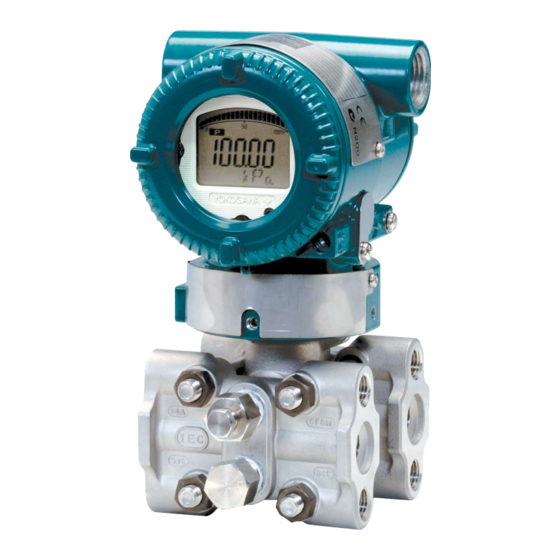
YOKOGAWA DPharp EJX Series User Manual (150 pages)
Digital Remote Sensor
Brand:
YOKOGAWA
| Category:
Transmitter
| Size: 10 MB
Table of Contents
Table of Contents
2
1 Introduction
7
Regarding this Manual
8
Trademarks
9
Safe Use of this Product
9
Warranty
10
2 Handling Cautions
11
Model and Specifications Check
11
Unpacking
11
Storage
12
Selecting the Installation Location
12
Pressure Connection
12
Waterproofing of Cable Conduit Connections and DRS Cable
13
Restrictions on Use of Radio Transceivers
13
Insulation Resistance and Dielectric Strength Test
13
Installation of an Explosion-Protected Instrument
14
FM Approval
14
ATEX Certification
19
Iecex Certification
22
Name Plate
25
3 Component Description
26
High Pressure Side Transmitter (Master)
26
Low Pressure Side Transmitter (Slave)
27
4 Installation
28
Precautions
28
Mounting
28
Connecting the DRS Cable
31
Mounting the C10FR Flushing Connection Ring
31
Mounting to Pressure Detector Section
31
Mounting to Process Flange
32
Affixing the Teflon Film
33
Tank Spud Mounting Method
33
Rotating Transmitter Section
35
Changing the Direction of Integral Indicator
35
5 Wiring
36
Wiring Precautions
36
Selecting the Wiring Materials
36
Connections of External Wiring to Terminal Box
36
Power Supply Wiring Connection
36
External Indicator Connection
36
Connecting The Hart Configuration Tool
37
Check Meter Connection
37
Wiring
37
Loop Configuration
37
Wiring Installation
37
DRS Cable Connection
38
Wiring through a Cable Gland
38
Wiring through a Wiring Metal Conduit
41
Removing DRS Cable with Cable Gland
41
Removing DRS Cable Running through a Wiring Metal Conduit
41
Fixing the DRS Cable
42
Grounding
42
Power Supply Voltage and Load Resistance
42
6 Operation
43
Preparation for Starting Operation
43
Zero Point Adjustment
44
Starting Operation
45
Shutting down Operation
45
Venting or Draining Transmitter Process-Detector Section
45
Draining Condensate from C10FR Flushing Connection Ring
46
Venting Gas from C10FR Flushing Connection Ring
46
Local Parameter Setting
47
Local Parameter Setting (LPS) Overview
47
Activating Local Parameter Setting
49
Parameter Setting Review
49
Tag Number Configuration
50
Differential Pressure Unit Configuration
50
Differential Pressure Lrv/Urv Configuration
50
Damping Time Constant Configuration
51
Output Mode Configuration
52
Display Out 1 Configuration
52
Re-Range By Applying Actual Pressure (Lrv/Urv)
52
Save or Cancel
52
Abort Configuration
53
Abort Configuration (Menu)
53
Abort Configuration (Parameter)
53
Local Parameter Setting Lock
53
Others
53
7 HART Communication
54
Connection
54
Integral Indicator Display at Power-On
54
Aligning Configuration Tool DD And Device Revision
55
Setting Parameters Using The Dtm
55
Connecting Dpharp And Configuration Tool
56
Setting Parameters
56
Menu Tree
56
DD and DTM Menu Tree
56
Basic Setup
57
Setting Process Variables
57
Tags and Device Information
57
Measuring Range
58
Unit
58
Differential Pressure Damping Time Constant
59
Output Mode
59
Output Signal Low Cut
60
Detail Setup
61
Pressure Damping Time Constant
61
Pressure Signal Setup
61
Bi-Directional Flow Measurement Setup
62
Impulse Line Connection Orientation Setup
62
Analog Signal Variable Range Setup
63
Integral Indicator Display Mode
63
Integral Indicator Setup
63
Display Temperature Unit Setup
65
Zero Point Adjustment and Span Adjustment
65
Analog Output Adjustment
68
CPU Error Burnout Switch and Hardware Write Protection
69
External Switch Mode
69
Software Write-Protect
69
Signal Characterizer Setup
70
Alarm Setup
71
Test Output, Simulation, and Squawk
72
Burst Mode
73
Multidrop Mode
79
Diagnostics
81
Self-Diagnostics
81
Checking Using the HART Configuration Tool
81
Checking with Integral Indicator
81
Status Information
81
NE107 Status Information
82
Advanced Diagnostics
83
What Is the Multi Sensing Process Monitoring Function
83
Impulse Line Blockage Detection
84
Blockage Determination
86
Combination of the Reference Value and Blockage Detection Result
87
Operation Parameters
89
Operating Procedure
91
Alert and Alarm Setup
92
Condition Confirmation
94
Checking the Blockage Detection Operating Capacity
95
Reference Value Acquisition
95
ILBD Execution
96
Tuning
96
ILBD Parameter List
98
Resetting the Reference Value
98
Heat Trace Monitoring
101
Alarm Generation
102
Flg Temp Coef Setting
102
Heat Trace Monitoring Parameter List
103
8 Maintenance
104
Overview
104
Calibration Instrument Selection
104
Calibration
106
Disassembly and Reassembly
107
Replacing the Integral Indicator
107
Replacing The Cpu Board Assembly
108
Cleaning and Replacing the Capsule Assembly
109
Troubleshooting
110
Basic Troubleshooting
110
Troubleshooting Flowcharts
110
Alarms and Countermeasures
112
9 Parameter Summary
128
10 General Specifications
141
Appendix 1. Safety Instrumented Systems Installation
142
A1.1 Scope and Purpose
142
A1.2 Using the Transmitter for an SIS Application
142
A1.2.1 Safety Accuracy
142
A1.2.2 Diagnostic Response Time
142
A1.2.3 Setup
142
A1.2.4 Required Parameter Settings
142
A1.2.5 Proof Testing
142
A1.2.6 Repair and Replacement
143
A1.2.7 Startup Time
143
A1.2.8 Firmware Update
143
A1.2.9 Reliability Data
143
A1.2.10 Lifetime Limits
144
A1.2.11 Environmental Limits
144
Application Limits
144
A1.3 Definitions and Abbreviations
144
A1.3.1 Definitions
144
A1.3.2
144
Abbreviations
144
Appendix 2. ILBD Check List
145
Revision Information
150
Advertisement
YOKOGAWA DPharp EJX Series User Manual (131 pages)
Fieldbus Communication Type
Brand:
YOKOGAWA
| Category:
Transmitter
| Size: 1 MB
Table of Contents
Table of Contents
2
1 Introduction
7
Regarding this Manual
7
Safe Use of this Product
8
Warranty
9
ATEX Documentation
9
2 Handling Cautions
11
Installation of an Explosion-Protected Instrument
11
FM Approval
11
CSA Certification
13
CENELEC ATEX Certification
14
3 About Fieldbus
18
Outline
18
Internal Structure of EJX
18
System/Network Management VFD
18
Function Block VFD
18
Logical Structure of each Block
18
Wiring System Configuration
18
4 Getting Started
19
Connection of Devices
19
Host Setting
20
Bus Power on
21
Integration of DD
21
Reading the Parameters
21
Continuous Record of Values
22
Generation of Alarm
22
5 Configuration
23
Network Design
23
Network Definition
23
Definition of Combining Function Blocks
24
Setting of Tags and Addresses
25
Communication Setting
26
VCR Setting
26
Function Block Execution Control
27
Block Setting
27
Link Object
27
Trend Object
28
View Object
28
Function Block Parameters
32
6 Explanation of Basic Items
33
Outline
33
Setting and Changing Parameters for the Whole Process
33
SENSOR Transducer Block
33
Functional Block
33
Block Mode
33
Functions Relating to Pressure/Differential Pressure
34
Functions Relating to Static Pressure
35
Functions Relating to Capsule and Amplifier Temperature
36
Block_Err
36
Xd_Error
36
LCD Transducer Block
37
Outline of the Functions
37
Block Mode
37
Display Contents of the Integral Indicator
37
Example Displays of the Integral Indicator
38
Procedure to Set the Built-In Display
39
Units that Can be Displayed on the LCD by the Automatic Link Function
41
AI Function Block
42
Function Blocks
42
Block Mode
42
Io_Opts
42
Status_Opt
42
Out_D
43
Basic Parameters of the AI Block
43
7 In-Process Operation
44
Mode Transition
44
Generation of Alarm
44
Indication of Alarm
44
Alarms and Events
44
Simulation Function
45
8 Device Information
46
Device Status
46
Status of each Parameter in Failure Mode
49
9 Parameter Lists
51
Resource Block
51
SENSOR Transducer Block
53
LCD Transducer Block
57
Al Function Block
59
10 General Specifications
61
Standard Specifications
61
OPTIONAL SPECIFICATIONS (for Explosion Protected Type)
61
Appendix 1. Signal Characterizer (SC) Block
64
A1.1 Schematic Diagram of Signal Characterizer Block
64
Input/Output Parameters
64
A1.2 Input Section
66
A1.2.1 Determining the Mode
66
A1.2.2 Judging BLOCK_ERR
66
A1.3 Line-Segment Factor Determination Section
67
A1.3.1 Conditions for Configuring Valid Coefficients
67
A1.4 List of Signal Characterizer Block Parameters
69
A1.5 Application Example
70
A1.5.1 Input Compensation
70
A1.5.2 Calorie Flow Compensation
70
A1.5.3 Backward Control
70
Appendix 2. Integrator (IT) Block
72
A2.1 Schematic Diagram of Integrator Block
72
A2.2 Input Process Section
73
A2.2.1 Determining Input Value Statuses
73
A2.2.2 Converting the Rate
73
A2.2.3 Converting Accumulation
74
A2.2.4 Determining the Input Flow Direction
74
A2.3 Adder
75
A2.3.1 Status of Value after Addition
75
A2.3.2 Addition
75
A2.4 Integrator
76
A2.5 Output Process
77
A2.5.1 Status Determination
77
A2.5.2 Determining the Output Value
78
A2.5.3 Mode Handling
79
A2.6 Reset
80
A2.6.1 Reset Trigger
80
A2.6.2 Reset Timing
80
A2.6.3 Reset Process
81
A2.7 List of Integrator Block Parameters
82
Appendix 3. Input Selector (IS) Block
84
A3.1 Input Selector Function Block Schematic
84
A3.2 Input Section
86
A3.2.1 Mode Handling
86
A3.2.2 MIN_GOOD Handling
86
A3.3 Selection
87
A3.3.1 OP_SELECT Handling
87
A3.3.2 SELECTION Handling
88
A3.4 Output Processing
94
A3.4.1 Handling of SELECTED
94
A3.4.2 out Processing
95
A3.4.3 Status_Opts
96
A3.5 List of Input Selector Block Parameters
96
A3.6 Application Example
97
Appendix 4. Arithmetic (AR) Block
98
A4.1 Arithmetic Function Block Schematic
98
A4.2 Input Section
99
A4.2.1 Main Inputs
99
A4.2.2 Auxiliary Inputs
99
A4.2.3 Input_Opts
100
A4.2.4 Relationship between the Main Inputs and PV
100
A4.3 Computation Section
101
A4.3.1 Computing Equations
101
A4.3.2 Compensated Values
101
A4.3.3 Average Calculation
101
A4.4 Output Section
101
A4.4.1 Mode Handling
102
A4.4.2 Status Handling
102
A4.5 List of the Arithmetic Block Parameters
103
Appendix 5. Pid Block
105
A5.1 Function Diagram
105
A5.2 Functions of PID Block
105
Algorithm
105
A5.7 Control Action Bypass
105
A5.10 Bumpless Transfer
105
A5.11 Setpoint Limiters
105
A5.12 External-Output Tracking
105
A5.13 Measured-Value Tracking
105
A5.17 Mode Shedding Upon Computer Failure
105
A5.4.1 PV-Proportional and -Derivative Type PID (I-PD) Control Algorithm
108
A5.17.1 Shed_Opt
112
A5.18 Alarms
112
A5.18.1 Block Alarm (BLOCK_ALM)
112
A5.18.2 Process Alarms
112
A5.19 Example of Block Connections
113
A5.20 View Object for PID Function Block
113
Appendix 6. Link Master Functions
115
A6.1 Link Active Scheduler
115
A6.2 Link Master
115
A6.3 Transfer of las
116
A6.4 LM Functions
117
A6.5 LM Parameters
118
A6.5.1 LM Parameter List
118
A6.5.2 Descriptions for LM Parameters
120
A6.6 Faqs
122
Appendix 7. Software Download
123
A7.1 Benefits of Software Download
123
A7.2 Specifications
123
A7.3 Preparations for Software Downloading
123
A7.4 Software Download Sequence
124
A7.5 Download Files
124
A7.6 Steps after Activating a Field Device
125
A7.7 Troubleshooting
126
A7.8 Resource Block's Parameters Relating to Software Download
126
A7.9 System/Network Management VFD Parameters Relating to Software Download
128
A7.10 Comments on System/Network Management VFD Parameters
129
Relating to Software Download
129
Revision Record
131
YOKOGAWA DPharp EJX Series User Manual (65 pages)
Low Flow Transmitter
Brand:
YOKOGAWA
| Category:
Transmitter
| Size: 5 MB
Table of Contents
Table of Contents
2
Introduction
5
Regarding this Manual
6
Trademarks
6
Safe Use of this Product
7
Warranty
9
Handling Cautions
10
Model and Specifications Check
10
Unpacking
10
Storage
11
Selecting the Installation Location
11
Pressure Connection
11
Waterproofing of Cable Conduit Connections
12
Restrictions on Use of Radio Transceivers
12
Insulation Resistance and Dielectric Strength Test
12
Installation of an Explosion-Protected Instrument
13
FM Approval
13
CSA Certification
15
CSA Explosionproof Type
16
ATEX Certification
18
Electrical Connection
21
Name Plate
22
Operation
22
Maintenance and Repair
22
Iecex Certification
23
EMC Conformity Standards
25
Pressure Equipment Directive (PED)
26
EU Rohs Directive
26
Safety Requirement Standards
26
Component Names
27
Installation
28
Precautions
28
Mounting
28
Changing the Manifold Assembly
29
Swapping the High/Low-Pressure Side Connection
29
Rotating Transmitter Section
30
Changing the Direction of Integral Indicator
30
Installing Impulse Piping
31
Process Piping Installation Precautions
31
Connecting Process Piping to the Transmitter
31
Routing the Process Piping
31
Process Piping Connection Examples
32
Wiring
33
Wiring Precautions
33
Selecting the Wiring Materials
33
Connections of External Wiring to Terminal Box
33
Power Supply Wiring Connection
34
External Indicator Connection
34
Communicator Connection
34
Check Meter Connection
34
Status Output Connection
35
Wiring
35
Loop Configuration
35
Wiring Installation
36
Flameproof Type
36
Grounding
37
Power Supply Voltage and Load Resistance
37
Operation
38
Preparation for Starting Operation
38
Zero Point Adjustment
40
Adjusting Zero Point for Differential Pressure Transmitters
40
Starting Operation
41
Shutting down Operation
41
Transmitter Measurement Range (Determining Differential Pressure Range)
42
Determining the Differential Pressure Range
42
Example of Calculation
43
Venting or Draining Transmitter Pressure-Detector Section
45
Draining Condensate
45
Venting Gas
45
Local Parameter Setting
46
Local Parameter Setting (LPS) Overview
46
Activating Local Parameter Setting
48
Parameter Setting Review
48
Loop Test Configuration
49
Tag Number Configuration
49
Pressure Unit Configuration
49
Pressure Lrv/Urv Configuration
50
Damping Time Constant Configuration
50
Output Mode Configuration
50
Display out 1 Configuration
50
Re-Range by Applying Actual Pressure (LRV/URV)
51
Device Information Display
51
Save or Cancel
51
Abort Configuration
52
Abort Configuration (Menu)
52
Abort Configuration (Parameter)
52
Local Parameter Setting Lock
52
Others
52
Maintenance
53
Overview
53
Calibration Instruments Selection
53
Calibration
53
Disassembly and Reassembly
55
Replacing the Integral Indicator
55
Replacing the CPU Board Assembly
56
Replacing the Process Connector Gaskets
56
Cleaning Manifold Assembly and Replacing Orifice
57
Cleaning and Replacing the Capsule Assembly
58
Troubleshooting
59
Basic Troubleshooting
59
Troubleshooting Flowcharts
60
Alarms and Countermeasures
62
General Specifications
63
Revision Information
64
Advertisement
YOKOGAWA DPharp EJX Series Manual (45 pages)
HART Communication Type
Brand:
YOKOGAWA
| Category:
Transmitter
| Size: 1 MB
Table of Contents
Table of Contents
2
1 Introduction
4
Regarding this Manual
4
Safe Use of this Product
5
Warranty
5
ATEX Documentation
6
Matching of Communicator DD and Instrument DD
7
2 Conditions of Communication Line
8
Interconnection between Dpharp and the HART Communicator
8
Communication Line Requirements
8
Power Supply Voltage and Load Resistance
8
3 Operation
9
Basic Operation of the 275 HART Communicator
9
Keys and Functions
9
Display
10
Calling up Menu Addresses
10
Entering, Setting, and Sending Data
11
Parameter Usage and Selection
12
Menu Tree
13
Basic Setup
14
Tag and Device Information
14
Unit
14
Range Change
15
Keypad Input
15
Apply Values
16
Output Mode
17
Damping Time Constant Setup
17
Output Signal Low Cut Mode Setup
18
Impulse Line Connection Orientation Setup
18
Detailed Setup
19
Bi-Directional Flow Measurement
19
Integral Indicator Display Mode
19
Integral Indicator Scale Setup
20
Unit for Displayed Temperature
22
Unit for Displayed Static Pressure
22
Test Output
23
Sensor Trim
24
Zero Trim
24
Auto Sensor Trim
25
Full Sensor Trim
25
Manual Sensor Trim
25
Reset Trim Adjustment to Factory Setting
26
Sensor Trim for Static Pressure
26
Trim Analog Output
26
Burst Mode
28
Multidrop Mode
29
External Switch Mode
30
CPU Failure Burnout Direction and Hardware Write Protect
30
Software Write Protect
31
Entering Password to Enable the Parameter Changes
31
Releasing Password
31
Setting Password
31
Software Seal
32
Signal Characterizer
32
Process Alarm
33
Status Output (Option Code AL)
34
Capillary Fill Fluid Density Compensation
35
4 Self-Diagnostics
37
Identify Problems by Using the Communicator
37
Checking with Integral Indicator
37
Alarm Message Summary
38
Alarms and Countermeasures
38
5 Parameter Summary
40
Appendix 1. Safety Instrumented Systems Installation
42
Revision Record
45
YOKOGAWA DPharp EJX Series User Manual (38 pages)
BRAIN Communication Type
Brand:
YOKOGAWA
| Category:
Transmitter
| Size: 1 MB
Table of Contents
Table of Contents
2
1 Introduction
4
Regarding this Manual
4
Safe Use of this Product
5
Warranty
5
ATEX Documentation
6
2 Conditions of Communication Line
7
Connecting the BT200
7
Communication Line Requirements
7
Power Supply Voltage and Load Resistance
7
3 Operation
8
BT200 Operating Procedures
8
Key Layout and Screen Display
8
Operating Key Functions
9
Alphanumeric Keys and Shift Keys
9
Function Keys
9
Calling up Menu Addresses Using the Operating Keys
10
Printout (for BT200 Printer Option)
10
Setting Parameters Using the BT200
11
Parameter Usage and Selection
11
Menu Tree
12
Setting Parameters
13
Tag No. Setup
13
Calibration Range Setup
13
Damping Time Constant Setup
14
Output Mode and Integral Indicator Display Mode Setup
15
Output Signal Low Cut Mode Setup
15
Integral Indicator Scale Setup
16
Unit Setup for Displayed Temperature
17
Operation Mode Setup
17
Impulse Line Connection Orientation Setup
18
CPU Failure Burnout Direction and Hardware Write Protect
18
Software Write Protect
18
Output Status Setup When a Hardware Error Occurs
19
Bi-Directional Flow Measurement Setup
19
Range Change While Applying Actual Inputs
20
Sensor Trim
21
Test Output Setup
24
Signal Characterizer
24
Process Alarm
25
Status Output (Option Code AL)
25
Capillary Fill Fluid Density Compensation
26
Adjustment Information and User Memo Fields
27
Displaying Data Using the BT200
27
Displaying Measured Data
27
Display Transmitter Model and Specifications
27
Parameter Summary
27
4 Self-Diagnostics
28
Checking for Problems
28
Identifying Problems with BT200
28
Checking with Integral Indicator
29
Alarms and Countermeasures
30
5 Parameter Summary
31
Appendix 1. Safety Instrumented Systems Installation
35
YOKOGAWA DPharp EJX Series User Manual (52 pages)
Differential Pressure and Pressure Transmitters
Brand:
YOKOGAWA
| Category:
Transmitter
| Size: 7 MB
Table of Contents
Table of Contents
1
1 Introduction
3
For Safe Use of Product
4
Warranty
5
Atex Documentation
6
2 Handling Cautions
7
Model and Specifications Check
8
Selecting the Installation Location
8
Pressure Connection
8
Installation Of An Explosion-Protected Instrument
8
Process Piping Installation Precautions (EJ115) 2
8
Installation 5
8
Emc Conformity Standards
17
Pressure Equipment Directive (PED)
18
Low Voltage Directive
19
3 Installation
20
Mounting
20
Mounting The Diaphragm Seals
20
Diaphragm Seals Installation Consideration
21
Mounting the Flushing Connection Ring
22
Affixing the Teflon Film
23
Rotating Transmitter Section
24
Changing the Direction of Integral Indicator
24
4 Installing Impulse Piping
25
Impulse Piping Installation Precautions
25
Impulse Piping Connection Examples
27
5 Wiring
30
Wiring Precautions
30
Connections of External Wiring to Terminal Box
30
Wiring
32
RTD Cable Connection (EJX910A/EJX930A)
33
Grounding
36
Power Supply Voltage and Load Resistance
36
6 Operation
37
Preparation for Starting Operation
37
Zero Point Adjustment
38
7 Errors and Countermeasures
39
8 Parameter Summary
42
YOKOGAWA DPharp EJX Series User Manual (40 pages)
BRAIN Communication Type
Brand:
YOKOGAWA
| Category:
Transmitter
| Size: 2 MB
Table of Contents
Table of Contents
2
1 Introduction
4
Safe Use of this Product
5
Warranty
6
2 Connection
7
Power Supply Voltage and Load Resistance
8
3 Operation
9
Function Keys
10
Calling up Menu Addresses Using the Operating Keys
11
Setting Parameters Using the BT200
12
G50 Auto Recover
13
Menu Tree
13
Setting Parameters
14
Damping Time Constant Setup
16
Integral Indicator Scale Setup
17
I10 Disp Out1
18
I13 Disp Out4
18
I30:Engr.unit
18
I32:Engr.exp
18
I33:Engr.lrv
18
I34:Engr.urv
18
Setup
19
Unit Setup for Displayed Temperature
19
CPU Failure Burnout Direction and Hardware Write Protect
20
Output Status Setup When a Hardware Error Occurs
21
Range Change While Applying Actual Inputs
22
Test Output Setup
26
Process Alarm
27
Status Output (Option Code AL)
28
Capillary Fill Fluid Density Compensation
29
Adjustment Information and User Memo Fields
30
Self-Diagnostics
31
Checking with Integral Indicator
32
See A60
34
Alphanumeric Characters
34
32000 To 32000, Unit 0.00 Specified in I30
34
0.000%/Degc
35
Mpa
35
Normal
35
Appendix 1. Safety Instrumented Systems Installation
39
YOKOGAWA DPharp EJX Series Installation Manual (60 pages)
Differential Pressure and Pressure Transmitters
Brand:
YOKOGAWA
| Category:
Transmitter
| Size: 11 MB
Table of Contents
Table of Contents
1
1 Introduction
2
For Safe Use of Product
4
Warranty
6
2 Handling Cautions
7
3 Installation
35
Mounting
35
4 Installing Impulse Piping
40
5 Wiring
45
Wiring Precautions
45
Wiring
48
Grounding
52
6 Operation
53
Preparation for Starting Operation
53
7 Errors and Countermeasures
56
Advertisement
Related Products
YOKOGAWA DP harp EJX Series
YOKOGAWA DpharpEJX vigilantplant EJX Series
YOKOGAWA Dpharp EJX310A
YOKOGAWA Dpharp EJX530A
YOKOGAWA Dpharp EJX210A
YOKOGAWA DP harp EJX110A
YOKOGAWA DP harp EJX130A
YOKOGAWA DP harp EJX310A
YOKOGAWA DP harp EJX430A
YOKOGAWA DP harp EJX210B
YOKOGAWA Categories
Measuring Instruments
Test Equipment
Transmitter
Controller
Media Converter
More YOKOGAWA Manuals
Login
Sign In
OR
Sign in with Facebook
Sign in with Google
Upload manual
Upload from disk
Upload from URL