
Subscribe to Our Youtube Channel
Related Manuals for YOKOGAWA DPharp EJX***A Series


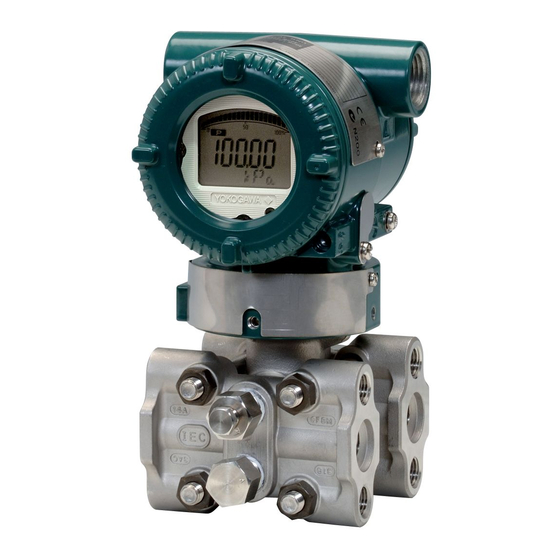
Summary of Contents for YOKOGAWA DPharp EJX***A Series
- Page 1 User’s Manual DPharp HART 5/HART 7 Communication Type (EJXA, EJAE) IM 01C25T01-06EN IM 01C25T01-06EN 7th Edition...
-
Page 2: Table Of Contents
3.2.8 Static Pressure Setup ..............3-15 Detailed Setup ....................3-16 3.3.1 Bi-directional Flow Measurement ............ 3-16 3.3.2 Analog Output Signal Adjustable Range ......... 3-16 7th Edition: Apr. 2019 (YK) IM 01C25T01-06EN All Rights Reserved, Copyright © 2010, Yokogawa Electric Corporation... - Page 3 Toc-2 3.3.3 Integral Indicator Display Mode ............3-16 3.3.4 Integral Indicator Scale Setup ............3-17 3.3.5 Unit for Displayed Temperature ............3-18 3.3.6 Sensor Trim ..................3-18 3.3.7 Trim Analog Output ................3-20 3.3.8 External Switch Mode ..............3-21 3.3.9 CPU Failure Burnout Direction and Hardware Write Protect ..
- Page 4 Toc-3 4.2.3 Heat Trace Monitoring..............4-21 4.2.3.1 Flg Temp Coef Setting ............ 4-21 4.2.3.2 Out of Temperature Measurement Range ...... 4-22 4.2.3.3 Parameter Lists for Heat Trace Monitoring ..... 4-23 Alarms and Countermeasures ..............4-24 Parameter Summary ................5-1 Appendix 1. Safety Instrumented Systems Installation ....A1-1 4-20mA...
-
Page 5: Introduction
Draws attention to information essential for written permission. understanding the operation and features. • Yokogawa makes no warranty of any kind with regard to this manual, including, but not limited to, implied warranty of merchantability and fitness for a particular purpose. -
Page 6: Safe Use Of This Product
<1. Introduction> Safe Use of This Product (e) Modification • Yokogawa will not be liable for malfunctions or For the safety of the operator and to protect the damage resulting from any modification made instrument and the system, please be sure to follow to this instrument by the customer. -
Page 7: Abbreviation And Marking
<1. Introduction> Abbreviation and Marking • mark indicates the specification or 4-20mA function applied for 4 to 20mA only. The following models, HART protocol revisions and • Unless otherwise stated or shown by a mark, configuration files are applied in this manual. the functions described in the chapter 3 are HART applicable for both 4 to 20 mA and 1 to 5 V... -
Page 8: Applicable Configuration Files
FDT2.0 HART 7 DTM The DTM is included in Yokogawa DTM Library HART 2012-2/Device Files R3.03.03 or later. The DTM is included in Yokogawa Device DTM Library 2.3/Device Files R3.03.03 or later. The DTM is included in Device DTM Library 4.0 or later. -
Page 9: Connection
<2. Connection> Connection Integral Indicator Display NOTE When Powering On LCD display can be set to “All segments display” For models with the integral indicator code “D” and only. “E”, the display shows all segments in the LCD • Procedure to call up the display and then changes to the displays shown below DD (HART 5/7) [Root Menu] (Refer to subsection... -
Page 10: Device Description (Dd) On A Configuration Tool And Transmitter Device Revision
<2. Connection> (a) Confirmation on the name plate NOTE The last numerical number engraved after Serial number and year of production shows HART 7 communication is supported by HART protocol revision number at the shipment FieldMate R2.02 or later. which is shown in Figure 2.1. NOTE MODEL STYLE... -
Page 11: Set The Parameters Using Dtm
FDT2.0 HART 7 DTM The DTM is included in Yokogawa DTM Library HART 2012-2/Device Files R3.03.03 or later. The DTM is included in Yokogawa Device DTM Library 2.3/Device Files R3.03.03 or later. The DTM is included in Device DTM Library 4.0 or later. -
Page 12: Interconnection Between Dpharp And The Hart Configuration Tool
<2. Connection> Interconnection Between Power Supply Voltage and DPharp and the HART Load Resistance 4-20mA Configuration Tool When configuring the loop, make sure that the external load resistance is within the range in the The HART configuration tool can interface with the figure below. -
Page 13: Parameter Setting
<3. Parameter Setting> Parameter Setting Menu Tree The structure of menu tree varies according to configuration tool based on DD or DTM. The difference is classified into two groups (I and II) as shown in the below table. HART protocol Applied model revision FDT1.2... - Page 14 <3. Parameter Setting> : HART 7 only HART 7 : EJX Series only • Diag/Service • Test device (DD) • Status • Status group 1 • Self test • Status group 2 • Master test • Status group 3 • Squawk •...
- Page 15 <3. Parameter Setting> : EJX Series only • Ratio fDP Status • Ratio fDP • Ratio fSPl Status • Ratio fSPl • Ratio fSPh Status • Ratio fSPh • BlkF Status • BlkF • DP Avg Status • DP Avg •...
- Page 16 <3. Parameter Setting> : HART 7 only HART 7 • Basic setup • Tag • Long tag HART 7 • Unit • Re-range • Keypad input • LRV • URV • Apply values • Unit • LSL • Date • Device infomation •...
- Page 17 <3. Parameter Setting> : HART 7 only HART 7 : EJX Series only • Detailed setup • Review • Pres • Sensors • Pressure sensor • Pres Zero trim • Pres % • Pres trim • Unit • P LTP •...
- Page 18 <3. Parameter Setting> : HART 5 only HART 5 : HART 7 only HART 7 : EJX Series only 4-20mA : 4-20mA output only 4-20mA • Burst Message 1 • Burst mode • Poll addr • Burst Command • Loop current mode •...
- Page 19 <3. Parameter Setting> : HART 7 only HART 7 • Detailed setup • Sensors • Disp Out1 • Signal condition • Disp Out2 • Review • Output condition • Disp Out3 • Display condition • Disp select • Disp Out4 •...
-
Page 20: Group Ii: Ejx Hart 5 Dtm Based On Fdt1.2
<3. Parameter Setting> 3.1.2 Group II: EJX HART 5 DTM based on FDT1.2 Root Menu • Process Variables • Device Status • Diag and Service • Easy Setup • Configuration • Calibration • Write Protect • Process Variables • Pres % • AO • URV • LRV • Xfer fnctn •... - Page 21 <3. Parameter Setting> • Service • Loop test • Diag Description • Diag and Service • Master test • BlkF • DO Test • fDP • Error log view • fSPh • Error log Clear • fSPl • Test Key •...
- Page 22 3-10 <3. Parameter Setting> • USL • Configuration • Pressure Sensor • LSL • Static Pressure • SP USL • Min span Sensor • SP LSL • Process Conn type • H/L Swap • Physical Information • SP Min Span •...
- Page 23 3-11 <3. Parameter Setting> • Calibration • Trim Who • Trim Date • Trim Loc • Trim Desc • Pres Zero trim • P UTP • P LTP • P UTD • P LTD • Pres trim • Clear P snsr trim •...
-
Page 24: Basic Setup
Configuration → Device information 1 → Unit → Descriptor Message Configuration → Device information 1 → Message Note that the Yokogawa default setting for the Date Configuration → Device information 1 standard temperature is 4°C (39.2°F). For the units → Date of mmH... -
Page 25: Range Change
3-13 <3. Parameter Setting> 3.2.3 Range Change (2) Apply values — changing the ranges while applying an actual Input The range values are factory-set as specified by This feature allows the lower and upper range the customer. To change the range, follow the steps values to be setup automatically with the actual below. -
Page 26: Damping Time Constant Setup
3-14 <3. Parameter Setting> 3.2.5 Damping Time Constant Setup The default value of Low cut is set according to the combination of the Output mode (Xfer fnctn) and The damping time constant is set as specified in Integral indicator display mode (Disp Pres % fnctn). the order when the instrument is shipped. -
Page 27: Impulse Line Connection Orientation Setup
3-15 <3. Parameter Setting> <Example> (2) Setting of the measuring range for static Output mode: Linear pressure Low cut mode: Zero Follow the procedure below to change the lower Low cut: 20.00% range value (LRV) and upper range value (URV). Output Low cut point •... -
Page 28: Detailed Setup
3-16 <3. Parameter Setting> Detailed Setup 3.3.2 Analog Output Signal Adjustable Range 3.3.1 Bi-directional Flow Measurement Output signal adjustable range at normal operating condition are set as shown below at the factory (a) Bi-dir mode enables selection of 50% output at when the instrument is shipped, and output signal an input of 0 mmH are limited by these value. -
Page 29: Integral Indicator Scale Setup
3-17 <3. Parameter Setting> 3.3.4 Integral Indicator Scale Setup Display Selection At Disp select, select the variable that the The following five displays are available for integral parameter Disp Out 1 will display on the integral indicators: input pressure, % of range, user set indicator. -
Page 30: Unit For Displayed Temperature
3-18 <3. Parameter Setting> User Setting of Engineering Unit and Scale Setting by EJX HART 5 DTM based on FDT1.2 Setting by DD and DTM (EJX HART 5 DTM User can input the desired unit at Engr Unit. based on FDT1.2) •... - Page 31 3-19 <3. Parameter Setting> (1) Zero Trim (2) Full Sensor Trim—Auto Trim and Manual Trim a. Zeroing—Pres Zero trim Full sensor trim is carried out by performing Auto, Pres Zero trim carries out the zero adjustment and Lower Pt followed by Auto, Upper Pt. automatically sets the applied “0” input values to the output value of “0”, keeping the span constant.
-
Page 32: Trim Analog Output
3-20 <3. Parameter Setting> <2> Suppose that a standard pressure of 1000 (4) Reset Trim Adjistment to Factory Setting O is applied and the value of the “Pres The Clear P snsr trim and Clear SP snsr trim for trim” is 994.0. Correct for this output error commands can reset the trim adjustment to the of 6 mmH O by adding 6 mmH... -
Page 33: External Switch Mode
3-21 <3. Parameter Setting> <Example> 3.3.9 CPU Failure Burnout Direction and Adjustment 4 to 20 mA output using a volt meter. Hardware Write Protect (4mA → 1V, 20mA → 5V) There are two slide switches on the CPU assembly 1) Select “Change”. board. One sets the burnout direction at CPU 2) Enter the value read on the voltmeter when the out- failure, and the other sets a write protection function which disables parameter changes through... -
Page 34: Software Write Protection
3-22 <3. Parameter Setting> 3.3.10 Software Write Protection To apply the settings to the output, set the S.C. parameter to “Enabled”. The transmitter configured data is saved by using a Note that the transmitter rejects the activation of the write protection function. The write protection status function by AL. -
Page 35: Alarm
3-23 <3. Parameter Setting> 3.3.12 Alarm DD and DTM [Root Menu] → Detailed (excluding EJX_ setup→ Output condition → The function is used to display the alarm codes HART 5[1.2]) Process Alerts → Temp Alert when the input pressure exceeds the specified (DTM only) →... -
Page 36: Status Output (Only For Ejx Series: Option Code Al)
3-24 <3. Parameter Setting> 3.3.13 Status Output (only for EJX series: Example: Status output operation of ON option code AL) WHEN AL. DETECT The transmitter has a contact output. Status output for higher alert value Select the type of output, status output, and set the unit, value etc. -
Page 37: Capillary Fill Fluid Density Compensation
3-25 <3. Parameter Setting> 3.3.14 Capillary Fill Fluid Density ● EJX118A/EJA118E Compensation For transmitters with diaphragm seals, this function is used to compensate the zero shift caused by the Transmitter ambient temperature effect on the capillary tubes. The following equation indicates the relationship between the calculated output value and the ●... -
Page 38: Test Output, Simulation, And Squawk
3-26 <3. Parameter Setting> 3.3.15 Test Output, Simulation, and Squawk Setting by EJX HART 5 DTM based on FDT1.2 NOTE Call up the test output parameter (Loop test) and select either manual test or auto test, and set the Fixed current output, DO Test, and Device current value. - Page 39 3-27 <3. Parameter Setting> (3) Device Variable Simulation Function (4) Squawk (Effective only when setting to (Effective only when setting to HART 7) HART 7) HART 7 HART 7 This feature can be used to identify the Using the simulation function, the output signal can communicating transmitter by remotely causing be confirmed by setting any value and status to the LCD to display the particular pattern as shown in selected device variable.
-
Page 40: Burst Mode
3-28 <3. Parameter Setting> 3.3.16 Burst Mode 3.3.16.2 In the case of using HART 7 HART 7 4-20mA 3.3.16.1 In the case of using HART 5 When the Burst mode is enabled, the transmitter HART 5 continuously sends up to three data listed in Table When the Burst mode is enabled, the transmitter 3.1. - Page 41 3-29 <3. Parameter Setting> Table 3.1 Burst parameters Burst Msg Trigger Burst Trigger Command parameter Burst Command Burst Trigger Units Mode Source Cmd1:PV Continuous (Pressure • Differential Window Depend on the Pressure) assigned variable to Rising Falling On-change % range/current Cmd2:% range/current Continuous (Percent of range, Loop...
- Page 42 3-30 <3. Parameter Setting> (2) Burst mode setting procedure • Procedure to call up the display DD and DTM [Root Menu] → Detailed setup → Output condition →HART output → Burst Condition → Burst Message 1,2 or 3 → Burst Command a.
- Page 43 3-31 <3. Parameter Setting> Burst Command • Procedure to call up the display DD and DTM [Root Menu] → Detailed setup Select the transmission data at Burst Command →Output condition →HART parameter. output → Burst condition → Burst Message 1,2 or 3 → Set Burst Burst Command Command parameter Period...
- Page 44 3-32 <3. Parameter Setting> Burst Mode Therefore, the configuration changes to the device are always detected as an event regardless of the When the Burst mode is set to “Wired HART setting of the Device Status. Enabled”, the transmitter starts to send the data. •...
-
Page 45: Multidrop Mode
3-33 <3. Parameter Setting> b) Acknowledge Event Notification 3.3.17 Multidrop Mode Execute Acknowledge Event Notification 3.3.17.1 Setting on HART 5 HART 5 method. “Multidropping” transmitters refer to the connection 1) Set to Enter Event Number is in confirmed of several transmitters to a single communication Event Number a)5. -
Page 46: Setting On Hart
3-34 <3. Parameter Setting> (4) Communication when set in multidrop 3.3.17.2 Setting on HART 7 HART 7 4-20mA mode. “Multidropping” transmitters refer to the connection of several transmitters to a single communication • The HART configuration tool searches for a transmission line. - Page 47 3-35 <3. Parameter Setting> 2) Activate the “Chg universal rev” method b. Confirm the new HART protocol revision number Call up the Universal rev parameter, and confirm IMPORTANT that the new HART revision number is displayed. The message is displayed to separate the •...
-
Page 48: Diagnostics
<4. Diagnostics> Diagnostics Self-Diagnostics When an improper operation is performed, the error message is displayed. 4.1.1 Identify Problems by Using HART See Table 4.6 HART Configuration Tool Error Configuration Tool Message. (2) EJX HART 5 DTM based on FDT1.2 The HART configuration tool can be used to run self-diagnostics on a transmitter and check for The Device Status commands are used for self- incorrect data settings. -
Page 49: Checking With Integral Indicator
<4. Diagnostics> 4.1.2 Checking with Integral Indicator (3) Data quality and Limit status The transmitter can handle PV (Pres), SV (SP), NOTE TV (Snsr temp), % rnge (Percent Range), and Loop current. Each variable contains data If an error is detected by running self-diagnostics, quality and limit status for providing useful an error number is displayed on the integral status about the data value. -
Page 50: Advanced Diagnostics (Only For Ejx Series)
<4. Diagnostics> (5) Configuration Change Counter 4.2.2 Impulse Line Blockage Detection (ILBD) The Configuration Change Counter is incremented once for every user action ILBD is carried out by using statistical analysis that changes the device’s configuration or based on the measured values of process calibration. - Page 51 <4. Diagnostics> Pressure Measurement • Operational pressure is near outside of diagnostic range. • Even though pressure is constant, the flow decreases than that under normal condition. • A source of pressure fluctuation (pump, compressor, blower, etc.) is shut down. As a result, the pressure fluctuation amplitude decreases.
- Page 52 <4. Diagnostics> Functional block diagram The figure below shows the functional block diagram of ILBD. Pres, Pres % Engr Disp SP, SP % Snsr temp Sensor Amp temp signals Process Value Output 4-20mA Sensor -------(6) calculation Blockage alarm Diag Output Option Contact Output Blockage alarm -------(7)
-
Page 53: Blockage Detection
<4. Diagnostics> 4.2.2.1 Blockage Detection Limit parameter When the parameter based on pressure fluctuation exceeds the preset value, EJX diagnoses an impulse line as blockage and gives an alarm. The threshold values are set to Limit parameter shown in below table. •... - Page 54 <4. Diagnostics> Table 4.3 Default Values of Limit Parameter Flange Diaphragm Gauge/ mounted sealed differential Absolute Gauge Differential pressure Absol ute differential pressure/ pressure pressure transmitter pressure pressure pressure transmitter transmitter transmitter Parameter transmitter transmitter EJX110A EJX120A EJX210A EJX118A EJX310A EJX430A EJX510A EJX115A...
-
Page 55: Combination Of Reference Result And Blockage Detection
<4. Diagnostics> L Side Blocking Detection 4.2.2.2 Combination of Reference Result and Blockage Detection BlkF is preferentially used to "L Side Blocking" detection. If BlkF cannot be used, Ratio fSPl, Diag Applicable SQRT (fSPl / Ref fSPl) is used to "L Side Blocking" The transmitter can detect four modes of impulse detection. -
Page 56: Operation Parameters
<4. Diagnostics> [Differential pressure measurement] Fluctuation Parameters Simulation Test Available Blockage Detection Ref fDP: • B Blocking detection • Test for low-pressure side (by using Ratio fDP) Ref fSPI: • L Side Blocking detection • Test for high-pressure side (by using Ratio fSPI) Ref fSPh: •... - Page 57 4-10 <4. Diagnostics> If Diag Supp Count is set to three times, an NOTE alarm is not generated at part ‘A’ in Figure 4.4. Because the first and second values only exceeded When setting ILBD parameters in the transmitter consecutively the threshold. via “Online Parameter”...
-
Page 58: Operating Procedure
4-11 <4. Diagnostics> 4.2.2.4 Operating Procedure If an alarm is often generated or the process condition changed in the ILBD operation, do The basic flow of the ILBD operation is as follows. tuning to change the alarm setting, or to reset the 1) Initial setting reference values. -
Page 59: Alarm And Alert Setting
4-12 <4. Diagnostics> 4.2.2.5 Alarm and Alert Setting (HART 5/HART 7) DTM (HART 5) Category The abnormal results as the blockage detection and DTM (HART 7) high/low flange temperature (heat trace monitoring) Not used Not used are given through an analog alert or the LCD Not used Not used display of alarm status. - Page 60 4-13 <4. Diagnostics> <Example> When the level range that can be measured by the (HART 5/HART 7) DTM (HART 5) DTM (HART 7) transmitter with 100 kPa span is –80 to 80 kPa, the A Blocking A Blocking limits are set as follows. Large Fluct L Large Fluctuation of Low Side •...
-
Page 61: Condition Check
4-14 <4. Diagnostics> • Procedure to call up the display 4.2.2.6 Condition Check DD and DTM [Root Menu] → Diag/Service → After the transmitter was installed, it is necessary to (excluding EJX_ Diag Parameters → Diag Output → confirm if Pres is stable under the normal operating HART 5[1.2]) Diag Fixed Out Val →... -
Page 62: Obtain Reference Values
4-15 <4. Diagnostics> Start of Sampling Table 4.4 Requirements to apply ILBD Condition The sampling of reference value is carried out for 7×10 or more 180 seconds, which is the default value set to Diag fSPI 1×10 or more Period. -
Page 63: Capability Test Of Blockage Detection Operation
4-16 <4. Diagnostics> Invalid Ref F, SPH, SPL, or DP Simulation of Low-pressure Side Blockage When the enough reference fluctuation value is not obtained, an alarm of invalid reference value 1) Close the low-pressure-side valve. for each parameter is generated and also the ILBD 2) Confirm the value of Pres is stable. -
Page 64: Tuning
4-17 <4. Diagnostics> 4.2.2.10 Tuning (1) Setting by DD and DTM (excluding EJX HART 5 DTM based on FDT1.2) When the pressure fluctuation amplitude in fluids is • Procedure to call up the threshold related not sufficiently large or an alarm is often generated display according to the process condition, tune up by changing the threshold for the blockage detection DD and DTM... -
Page 65: Reset Of Reference Value
4-18 <4. Diagnostics> Ratio fDP Compensation Combination of threshold for sensitivity parameter High Medium When the flow change is too large or small, an Lim fDPmax 1.50 3.00 3.00 alarm maybe often generated. When the above Lim fDPmin 0.40 0.30 0.20 case happens, the Ratio fDP can be compensated... -
Page 66: Ilbd Parameter List
4-19 <4. Diagnostics> 4.2.2.12 ILBD Parameter List # Parameter name Default value Explanation 1 Diag Error 0x0000 The results detected by ILBD or Heat trace monitoring are stored into this parameter. Also the condition abnormality in the diagnostic process is stored as an error. 2 Diag Option 0x08FC The masking in this parameter enable to display each error message and the... - Page 67 4-20 <4. Diagnostics> # Parameter name Default value Explanation 28 Ref fSPl Value of fSPl obtained under normal condition. 29 Ref fSPl Status Status of fSPl obtained under normal condition. 30 Ref fSPh Value of fSPh obtained under normal condition. Status of fSPh obtained under normal condition.
-
Page 68: Heat Trace Monitoring
4-21 <4. Diagnostics> 4.2.3 Heat Trace Monitoring 4.2.3.1 Flg Temp Coef Setting The transmitter with Heat trace monitoring function The value calculated according to the following calculates the flange temperature by using the two procedure is set to Flg Temp Coef. temperature sensors built in the transmitter. •... -
Page 69: Out Of Temperature Measurement Range
4-22 <4. Diagnostics> Sensor signals Sensor Process Value 4-20mA DC calculation (Analog Output) Amplifier Amp temp Amp temp Temperature Capsule Snsr temp Snsr temp Temperature HTM alarm HTM alarm Diag Output Contact Output Calculation of DO Config Option (Digital Output) Flg temp Flg Temp Coef CT+(CT-AT) x Cf... -
Page 70: Parameter Lists For Heat Trace Monitoring
4-23 <4. Diagnostics> 4.2.3.3 Parameter Lists for Heat Trace Monitoring Parameter name Default value Explanation 1 Diag Error 0x0000 The results detected by ILBD or Heat trace monitoring are stored into this parameter. Also the condition abnormality in the diagnostic process is stored as an error. -
Page 71: Alarms And Countermeasures
4-24 <4. Diagnostics> Alarms and Countermeasures Table 4.5 Alarm Message Summary Status Diagnostic Integral HART configuration 4-20mA Output Cause Countermeasure group List indicator tool display operation during error group * AL. 01 P sensor error * Sensor problem. Outputs the signal (High Replace capsule if CAP.ERR Pressure Sensor... - Page 72 4-25 <4. Diagnostics> Status Diagnostic Integral HART configuration 4-20mA Output Cause Countermeasure group List indicator tool display operation during error group * AL. 50 Illegal P LRV * Specified value is outside Holds at the output value Check settings and P. LRV Illegal Pressure LRV of setting range.
- Page 73 4-26 <4. Diagnostics> Status Diagnostic Integral HART configuration 4-20mA Output Cause Countermeasure group List indicator tool display operation during error group * AL. 79 — Displayed value exceeds Continues to operate and Check settings and OV. DISP limit. output. change them as —...
- Page 74 4-27 <4. Diagnostics> Table 4.6 HART Configuration Tool Error Messages Error message Probable cause Countermeasure Invalid selection — Change the setting. Value was too high Set value is too high. Value was too low Set value is too low. Too few data bytes received — —...
- Page 75 4-28 <4. Diagnostics> Table 4.10 Relationship between Alarm and Status available for HART 7 Value and Status (Data Quality and Limit Status) Integral HART configuration Extended Differential Static Device Status Temperature Indicator tool display Device Status Pressure Pressure % range Loop current (DP) (SP) AL.01...
- Page 76 4-29 <4. Diagnostics> Value and Status (Data Quality and Limit Status) Integral HART configuration Extended Differential Static Device Status Temperature Indicator tool display Device Status Pressure Pressure % range Loop current (DP) (SP) AL.35 P high alarm * Device Value: Measured value P.
- Page 77 4-30 <4. Diagnostics> Value and Status (Data Quality and Limit Status) Integral HART configuration Extended Differential Static Device Status Temperature Indicator tool display Device Status Pressure Pressure % range Loop current (DP) (SP) AL.87 FT high alarm * Maintenance Value: Measured value In the case “Off”...
- Page 78 4-31 <4. Diagnostics> Value and Status (Data Quality and Limit Status) Integral HART configuration Extended Differential Static Device Status Temperature Indicator tool display Device Status Pressure Pressure % range Loop current (DP) (SP) AL.91 P Simulate Mode --- Device Value and Value: Measured value According to the setting of P.
-
Page 79: Parameter Summary
<5. Parameter Summary> Parameter Summary Contents and Default values in the table are for 4 to 20 mA output type. For 1 to 5 V output, replace the current mA value with corresponding voltage V value. Refer to ‘1.3 Abbreviation and Marking.’ Function Label Item... - Page 80 Country Country code US, JP, DE, FR, ES, RU, CN HART 7 Dev id Device ID Distributor Yokogawa Drain vent matl Drain and vent plug material Extra No. Customizaion number Ext SW External zeroing permission Disabled or Enabled Enabled...
- Page 81 <5. Parameter Summary> Function Label Item Contents Default value Handling Diag Lim Lim fDPmax Upper limit for Ratio fDP Refer to Table 4.2.3 Lim fDPmin Lower limit for Ratio fDP Refer to Table 4.2.3 Lim fSPlmax Upper limit for Ratio fSPl Refer to Table 4.2.3 Lim fSPlmin Lower limit for Ratio fSPl...
- Page 82 <5. Parameter Summary> Function Label Item Contents Default value Handling Diag Variables Ratio fDP SQRT (fDP/Ref fDP). Ratio fDP Status Status of Ratio fDP Ratio fSPl SQRT (fSPl/Ref fSPl). Ratio fSPl Status Status of Ratio fSPl Ratio fSPh SQRT (fSPh/Ref fSPh). Ratio fSPh Status Status of Ratio fSPh BlkF...
- Page 83 <5. Parameter Summary> Function Label Item Contents Default value Handling Event Event Notification Event Notification (Enable event notification on Notification Control token-passing data link layer, Off) 4-20mA HART 7 Device Status Event Masking Mask HART 7 Status group 1 to 10 Mask HART 7 Ext dev status...
- Page 84 <5. Parameter Summary> Function Label Item Contents Default value Handling Event Event Notification Event Notification Retry Time Notification Retry Time 4-20mA HART 7 Max Update Time Max Update Time for Event Notification HART 7 Event Debounce Event Debounce Interval Debounce Interval to detect Interval an event.
- Page 85 <5. Parameter Summary> Function Label Item Contents Default value Handling Flg temp Flg temp Calculated flange temperature value Flg Temp Coef Flg Temp Coef Flg Temp Lim Flg Temp Hi Alart Upper limit of Flange temperature 120 °C (deg C) Flg Temp Lo Alart Lower limit of Flange temperature -40 °C (deg C)
- Page 86 <5. Parameter Summary> Function Label Item Contents Default value Handling Process Alerts Digital Output Display of contact output Off or On DO Select Contact output select Off, Combination of Pres, SP and Temp DO Signal type Signal type select ON WHEN AL. DETECT, OFF ON WHEN AL.
- Page 87 <5. Parameter Summary> Function Label Item Contents Default value Handling Process Engr Disp User scaled value variables Engr Unit User set engineering unit Unit specified in Set Engr Unit 8 alphanumerics Loop Current (DD) Loop current value 3.6 to 21.6 mA AO (DTM) (Analog Output Current) HART 7...
- Page 88 5-10 <5. Parameter Summary> Function Label Item Contents Default value Handling Process TV (DD) Temperature value Capsule temperature variables Snsr temp (DTM) TV (Temp) Data Device variable process data Device variable process data Good Quality quality quality of TV (Temp) HART 7 TV (Temp) Limit Device variable limit status...
- Page 89 5-11 <5. Parameter Summary> Function Label Item Contents Default value Handling SP setup A/G Select Gauge/Abs select for static Gauge or Absolute Absolute pressure Atm. Pres Value Conversion coefficient 101.3 kPa SP Apply values Rerange for static pressure “0%, 100%, or Exit” SP Damp Damping time constant for SP 0.00 to 100.00...
-
Page 90: Safety Instrumented Systems Installation
Failures that are detected A1.2.3 Setup should be reported to Yokogawa. During installation the transmitter must be setup The personnel performing the proof test of the with engineering units parameters. This is typically transmitter should be trained in SIS operations done with a handheld terminal. -
Page 91: A1.2.6 Repair And Replacement
Yokogawa. Website address: https://www.yokogawa.com/ A1.2.11 Environmental Limits solutions/products-platforms/field-instruments/) is available from Yokogawa with all failure rates and The environmental limits of the transmitter are failure modes. specified in the user’s manual IM 01C25. IM 01C25T01-06EN... -
Page 92: A1.2.12 Application Limits
A1-3 <Appendix1. Safety Instrumented Systems Installation> A1.2.12 Application Limits Safety Assessment The investigation to arrive at a judgment -based on evidence- The application limits of the transmitter are specified of the safety achieved by in the user’s manual IM 01C25. If the transmitter is safety-related systems used outside of the application limits, the reliability Further definitions of terms used for safety... -
Page 93: Appendix 2. Ilbd Check List
A2-1 <Appendix2. ILBD Check List> Appendix 2. ILBD Check List Fill out the below checklist according to the operation flow of the ILBD in order to keep the important information for the blockage detection. Checklist (1/5) Items Parameters Result Example 4-20 mA Analog Signal Setting Off: ... - Page 94 A2-2 <Appendix2. ILBD Check List> Checklist (2/5) Items Parameters Result Example Alarm status Diag Error A Blocking • Check the alarm status shown in Diag Error. Large Fluct L • Check that the alarm status of “ILBD over ...
- Page 95 A2-3 <Appendix2. ILBD Check List> Checklist (3/5) Go to the following step according to the result of "Invalid Ref xx" shown in the Diag Error of 8th check item. Diag Error Check item Invalid Ref SPH Invalid Ref SPL Invalid Ref DP →...
- Page 96 A2-4 <Appendix2. ILBD Check List> Checklist (4/5) Items Parameters Result Example 10-a-2 L Side Blocking • Close the low-pressure side valve completely. • Record the values of fDP, fSPl, fSPh, BlkF, fDP* 7.48562E-09 and DPAvg after the certain time, fSPI* 7.23277E-09 (Diag Period X Diag Supp Count), passed.
- Page 97 A2-5 <Appendix2. ILBD Check List> Checklist (5/5) Items Parameters Result Example 10-b Simulation of Blockage detection operation • Close completely the valve for the side where the alarm of Invalid Reference Value is not generated. For the case that the high-pressure side value is closed;...
-
Page 98: Revision Information
Rev-1 Revision Information Title : DPharp HART 5/HART 7 Communication Type (EJXA, EJAE) Manual No. : IM 01C25T01-06EN Edition Date Page Revised Item June 2010 — New publication Apr. 2012 — Re-edit to a common User’s Manual of HART 5 and HART 7. Add integral indicator display when powering on.
Need help?
Do you have a question about the DPharp EJX***A Series and is the answer not in the manual?
Questions and answers